Model If114 Vats/passlock/transponder Universal ... - Bulldog Security
Model If114 Vats/passlock/transponder Universal ... - Bulldog Security
Model If114 Vats/passlock/transponder Universal ... - Bulldog Security

Create successful ePaper yourself
Turn your PDF publications into a flip-book with our unique Google optimized e-Paper software.
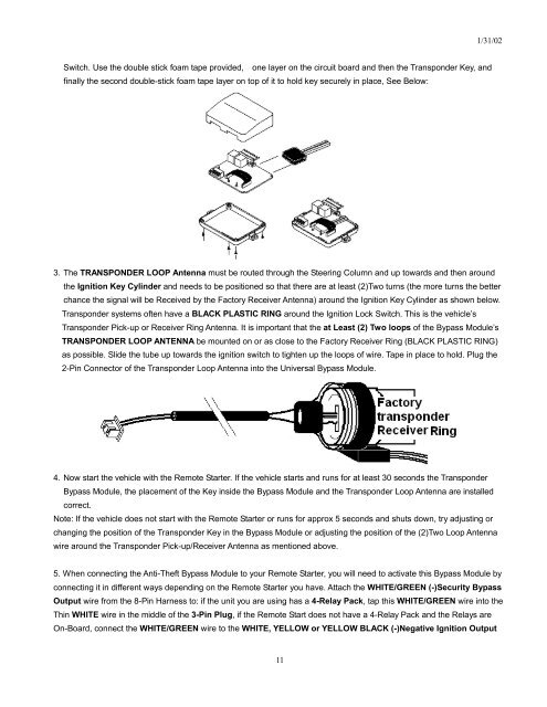
Switch. Use the double stick foam tape provided, one layer on the circuit board and then the Transponder Key, and<br />
finally the second double-stick foam tape layer on top of it to hold key securely in place, See Below:<br />
3. The TRANSPONDER LOOP Antenna must be routed through the Steering Column and up towards and then around<br />
11<br />
1/31/02<br />
the Ignition Key Cylinder and needs to be positioned so that there are at least (2)Two turns (the more turns the better<br />
chance the signal will be Received by the Factory Receiver Antenna) around the Ignition Key Cylinder as shown below.<br />
Transponder systems often have a BLACK PLASTIC RING around the Ignition Lock Switch. This is the vehicle’s<br />
Transponder Pick-up or Receiver Ring Antenna. It is important that the at Least (2) Two loops of the Bypass Module’s<br />
TRANSPONDER LOOP ANTENNA be mounted on or as close to the Factory Receiver Ring (BLACK PLASTIC RING)<br />
as possible. Slide the tube up towards the ignition switch to tighten up the loops of wire. Tape in place to hold. Plug the<br />
2-Pin Connector of the Transponder Loop Antenna into the <strong>Universal</strong> Bypass Module.<br />
4. Now start the vehicle with the Remote Starter. If the vehicle starts and runs for at least 30 seconds the Transponder<br />
Bypass Module, the placement of the Key inside the Bypass Module and the Transponder Loop Antenna are installed<br />
correct.<br />
Note: If the vehicle does not start with the Remote Starter or runs for approx 5 seconds and shuts down, try adjusting or<br />
changing the position of the Transponder Key in the Bypass Module or adjusting the position of the (2)Two Loop Antenna<br />
wire around the Transponder Pick-up/Receiver Antenna as mentioned above.<br />
5. When connecting the Anti-Theft Bypass Module to your Remote Starter, you will need to activate this Bypass Module by<br />
connecting it in different ways depending on the Remote Starter you have. Attach the WHITE/GREEN (-)<strong>Security</strong> Bypass<br />
Output wire from the 8-Pin Harness to: if the unit you are using has a 4-Relay Pack, tap this WHITE/GREEN wire into the<br />
Thin WHITE wire in the middle of the 3-Pin Plug, if the Remote Start does not have a 4-Relay Pack and the Relays are<br />
On-Board, connect the WHITE/GREEN wire to the WHITE, YELLOW or YELLOW BLACK (-)Negative Ignition Output