Model If114 Vats/passlock/transponder Universal ... - Bulldog Security
Model If114 Vats/passlock/transponder Universal ... - Bulldog Security
Model If114 Vats/passlock/transponder Universal ... - Bulldog Security

Create successful ePaper yourself
Turn your PDF publications into a flip-book with our unique Google optimized e-Paper software.
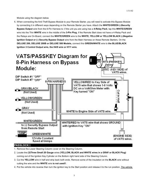
Module using the diagram below.<br />
6. When connecting the Anti-Theft Bypass Module to your Remote Starter, you will need to activate this Bypass Module<br />
by connecting it in different ways depending on the Remote Starter you have. Attach the WHITE/GREEN (-)<strong>Security</strong><br />
5<br />
1/31/02<br />
Bypass Output wire from the 8-Pin Harness to: if the unit you are using has a 4-Relay Pack, tap this WHITE/GREEN<br />
wire into the Thin WHITE wire in the middle of the 3-Pin Plug, if the Remote Start does not have a 4-Relay Pack and<br />
the Relays are On-Board, connect the WHITE/GREEN wire to the WHITE, YELLOW or YELLOW BLACK (-)Negative<br />
Ignition Output or (-) <strong>Security</strong> Bypass Output wire from the Main Harness on these Remote Starters. On the<br />
DELUXE 200, DELUXE 200B or DELUXE 500 <strong>Model</strong>s, connect this GREEN/WHITE wire to the BLUE/BLACK<br />
Ignition 3 Control Output wire, the H4/9 wire or H7/1 wire.<br />
PASSLOCK I:<br />
1. Remove the Lower Steering Column cover on the Steering Column.<br />
2. Locate the (3)Three Small 20 Gauge wires (YELLOW, BLACK and WHITE wires in a GRAY or BLACK Plug)<br />
coming out of the Ignition Key Cylinder on the Bottom right hand side of the Steering Column.<br />
3. Cut the YELLOW wire in half and strip back both ends. Remove some of the insulation on the BLACK wire without<br />
cutting the wire and the WHITE wire is not used!!.<br />
4. Put the vehicle into reverse then turn the ignition key to the Start position and release it to the run position. The vehicle