Numerical simulations of SFRC precast tunnel segments
Numerical simulations of SFRC precast tunnel segments
Numerical simulations of SFRC precast tunnel segments

You also want an ePaper? Increase the reach of your titles
YUMPU automatically turns print PDFs into web optimized ePapers that Google loves.
Underground Space Use: Analysis <strong>of</strong> the Past and Lessons for the Future – Erdem & Solak (eds)<br />
© 2005 Taylor & Francis Group, London, ISBN 04 1537 452 9<br />
<strong>Numerical</strong> <strong>simulations</strong> <strong>of</strong> <strong>SFRC</strong> <strong>precast</strong> <strong>tunnel</strong> <strong>segments</strong><br />
G.A. Plizzari & L. Cominoli<br />
Department <strong>of</strong> Engineering Design and Technologies, University <strong>of</strong> Bergamo, Italy<br />
ABSTRACT: The paper addresses <strong>precast</strong> <strong>tunnel</strong> <strong>segments</strong> for the new Line 9 <strong>of</strong> the Barcelona (Spain) Metro<br />
where the conventional reinforcement (rebars) may be partially substituted by steel fibers.<br />
After the experimental determination <strong>of</strong> the material properties, NonLinear Fracture Mechanics analyses<br />
allowed to study the structural behavior <strong>of</strong> the <strong>tunnel</strong> <strong>segments</strong> with different types <strong>of</strong> reinforcement. Finally, an<br />
optimized reinforcement, based on a combination <strong>of</strong> rebars and steel fibers, is proposed.<br />
1 INTRODUCTION<br />
Fiber Reinforced Concretes (FRC) are composite materials<br />
with a cementitious matrix and a discontinuous<br />
reinforcement (the fibers) that may be made <strong>of</strong> metal,<br />
glass, synthetic or natural materials.<br />
After almost four decades <strong>of</strong> research, mechanical<br />
properties <strong>of</strong> FRC have become well known, Standards<br />
for material characterization are widely available and<br />
design guidelines have been recently proposed<br />
(Naaman & Reinhardt, 2003; di Prisco et al., 2004;<br />
RILEM, 2002).<br />
Among the structural applications <strong>of</strong> FRC, there is<br />
a growing interest in <strong>precast</strong> <strong>tunnel</strong> <strong>segments</strong> to be<br />
used with the Tunnel Boring Machine (TBM), where<br />
steel fibers may substitute, partially or totally, the<br />
conventional reinforcement (rebars).<br />
In the present paper, the structural behavior <strong>of</strong> the<br />
<strong>tunnel</strong> <strong>segments</strong> for the new Metro line (Line 9) <strong>of</strong><br />
Barcelona (Spain) are numerically simulated with FE<br />
analyses based on Non Linear Fracture Mechanics<br />
(NLFM; Hillerborg et al., 1976).<br />
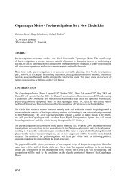
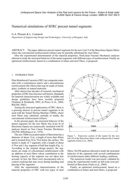
The new TBM-excavated <strong>tunnel</strong> <strong>of</strong> Barcelona has a<br />
diameter <strong>of</strong> about 12 m, a length <strong>of</strong> more than 40 km<br />
and is located from 30 to 70 m below the surface. The<br />
<strong>tunnel</strong> is made <strong>of</strong> 7 <strong>segments</strong> with a length <strong>of</strong> about<br />
4.70 m and 1 key segment <strong>of</strong> half that length (Fig. 1).<br />
According to the original design project, the <strong>segments</strong><br />
are made <strong>of</strong> conventional reinforcement with<br />
an addition <strong>of</strong> steel fibers whose contribution to the<br />
bearing capacity <strong>of</strong> the segment was not taken into<br />
account. In fact, the fibers were incorporated only to<br />
control cracking that may occur during handling and<br />
placing <strong>of</strong> the <strong>segments</strong>.<br />
After the experimental characterization <strong>of</strong> the<br />
material properties <strong>of</strong> FRC with two types <strong>of</strong> steel<br />
1105<br />
Figure 1. Transverse section <strong>of</strong> the <strong>tunnel</strong> for the new<br />
line (9) <strong>of</strong> the Barcelona Metro with evidenced the 8 <strong>tunnel</strong><br />
<strong>segments</strong> (Gettu et al., 2004).<br />
fibers, NLFM analyses allowed to study the structural<br />
behavior <strong>of</strong> the <strong>segments</strong> with several combinations<br />
<strong>of</strong> reinforcement under different loading conditions.<br />
The numerical model was previously validated by<br />
using the experimental results on full-scale tests performed<br />
in Barcelona (Gettu et al., 2004).<br />
Finally, an optimized reinforcement, based on a<br />
combination <strong>of</strong> rebars and steel fibers, is proposed.
Table 1. Concrete composition (quantities refer to 1 m 3 ).<br />
2 MATERIALS<br />
Weight [Kg] Volume [l]<br />
Cement Portland 52,5R 425 134,92<br />
Water 142 142<br />
Superplasticiser – 3,20<br />
Aggregates 1885 699,88<br />
Air assumed – 20,00<br />
Water/cement ratio 0,33 –<br />
Table 2. Geometrical characteristic <strong>of</strong> the fibers.<br />
Fiber L f � f L f/� f<br />
code [mm] [mm] [-] Fiber shape<br />
Wirand 50.0 1.00 50.0<br />
FF1<br />
Wirand 50.0 0.75 67.0<br />
FF3<br />
The concrete matrix was made with cement CEM I<br />
52.5R (UNI-ENV 197) and a natural river gravel with<br />
a rounded shape and a maximum diameter <strong>of</strong> 15 mm;<br />
its composition is summarized in Table 1. The grain<br />
size distribution <strong>of</strong> aggregates was chosen very close<br />
to the Bolomey curve by using nine classes <strong>of</strong> aggregates.<br />
An acrylic based super-plasticizer was used.<br />
The two different types <strong>of</strong> fibers that were considered<br />
in this research are reported in Table 2 where<br />
the fiber length (L f), the fiber diameter (� f) and the<br />
aspect ratio (L f/� f) are shown. All the fibers are cold<br />
drawn, have a hooked shape, a rounded shaft and a<br />
tensile strength higher than 1100 MPa.<br />
Fibers with an aspect ratio equal to 50 (FF1) were<br />
used with two different volume fractions (V f), equal<br />
to 0.45% (35 kg/m 3 ) and to 0.58% (45 kg/m 3 ). Fibers<br />
with a higher aspect ratio (FF3) were used with a<br />
lower dosage, equal to 25 kg/m 3 (V f � 0.32%) and to<br />
35 kg/m 3 (V f � 0.45%).<br />
Eight beam specimens were made for each type <strong>of</strong><br />
<strong>SFRC</strong>; in addition, 8 beams <strong>of</strong> plain concrete were<br />
used as reference specimens.<br />
The slump(s) <strong>of</strong> the fresh concrete was always<br />
greater than 150 mm.<br />
Specimens were stored in a fog room (R.H. � 95%;<br />
T � 20 � 2°C) until 24 hours before testing.<br />
Table 3 reports the mechanical properties <strong>of</strong> concrete<br />
(average values), as determined after about<br />
60 days <strong>of</strong> curing; in particular, tensile strength (f ct)<br />
from cylinders (� �80 mm, L � 240 mm), compressive<br />
strength from cubes (f c,cube) having 150 mm side<br />
and Young’s modulus (E c) from compression tests on<br />
cylinders (� �80 mm, L � 240 mm), are reported.<br />
1106<br />
Table 3. Mechanical properties <strong>of</strong> concrete (average values).<br />
f c,cube [MPa] f ct [MPa] E c [GPa]<br />
FF1 64.7 64.1 4.11 4.07 38.8 38.1<br />
FF3 63.5 4.04 37,4<br />
Figure 2. Geometry (a) and instrumentation (b) <strong>of</strong> the<br />
notched specimen for the beam tests.<br />
Fracture properties were determined from notched<br />
beams (150 � 150 � 600 mm) tested under four point<br />
bending according to the Italian Standard (UNI, 2003;<br />
Fig. 2a). The tests were carried out with a closed-loop<br />
hydraulic testing machine by using the Crack Mouth<br />
Opening Displacement (CMOD) as a control parameter,<br />
which was measured by means <strong>of</strong> a clip gauge<br />
positioned astride a notch in the mid-span, having a<br />
depth <strong>of</strong> 45 mm (Fig. 2a). Additional Linear Variable<br />
Differential Transformers (LVDTs) were used to<br />
measure the Crack Tip Opening Displacement (CTOD)<br />
and the vertical displacement at the beam mid span<br />
and under the load points (Fig. 2b).<br />
Figure 3 shows typical experimental results from<br />
bending tests on beams with fibers FF1.<br />
Inverse analyses <strong>of</strong> the bending tests, based on<br />
NLFM, allowed to determine the best-fitting s<strong>of</strong>tening<br />
law for the <strong>SFRC</strong>s adopted in the present research<br />
(Roelfstra & Wittmann, 1986). The Young’s modulus<br />
(E c) was the one experimentally measured from the
Nominal Stress σ N [MPa]<br />
Nominal Stress σ N [MPa]<br />
6<br />
5<br />
4<br />
3<br />
2<br />
1<br />
R60- FF1 - 35 kg/m 3 - V f =0,45%<br />
0<br />
0.0 0.1 0.2 0.3 0.4 0.5<br />
9<br />
8<br />
7<br />
6<br />
5<br />
4<br />
3<br />
2<br />
1<br />
CTOD m [mm]<br />
Experimental<br />
<strong>Numerical</strong><br />
R60- FF1 - 45 kg/m 3 - V f =0,57%<br />
Experimental<br />
<strong>Numerical</strong><br />
0<br />
0.0 0.1 0.2 0.3 0.4 0.5<br />
CTOD m [mm]<br />
Figure 3. Experimental and numerical results obtained<br />
from beam tests on beams with fibers FF1.<br />
Figure 4. Bilinear law for the approximation <strong>of</strong> the postcracking<br />
behavior <strong>of</strong> <strong>SFRC</strong>.<br />
cylinders while the Poisson ratio (�) was assumed<br />
equal to 0.15. The s<strong>of</strong>tening law was approximated as<br />
bilinear where the first steeper branch can be associated<br />
with (unconnected) micro-cracking ahead <strong>of</strong> the<br />
stress-free crack while the second branch represents<br />
the aggregate interlocking or the fiber bridging (Fig. 4).<br />
The numerical analyses were initially performed by<br />
assuming both a discrete crack approach with Merlin<br />
(1994) and a smeared crack approach with Abaqus<br />
(release 6.4.1; 2003); the latter was also used for the<br />
numerical <strong>simulations</strong> <strong>of</strong> the <strong>tunnel</strong> <strong>segments</strong>.<br />
(a)<br />
(b)<br />
1107<br />
Figure 5. Mesh adopted for the numerical <strong>simulations</strong> <strong>of</strong><br />
the beam tests based on a discrete crack approach.<br />
Table 4. Parameters for the bilinear s<strong>of</strong>tening law for<br />
cracked concrete.<br />
<strong>SFRC</strong> V f (%) f ct [MPa] w 1 [mm] � 1 [MPa] w cr [mm]<br />
FF1 0.45 4.1 0.031 1.450 3.50<br />
0.58 4.1 0.023 2.134 5.35<br />
FF3 0.32 4.1 0.031 1.227 3.2<br />
0.45 4.1 0.028 1.505 3.9<br />
Figure 5 shows the mesh used for Merlin with triangular<br />
plain stress elements and interface elements<br />
for the crack. The material parameters identified from<br />
the bending tests (f ct, � 1, w 1, w cr) are summarized in<br />
Table 4. The best-fitting numerical curves obtained<br />
with Merlin are compared with the experimental ones<br />
in Figure 3.<br />
2 VALIDATION OF THE FE MODEL<br />
Experimental studies on the <strong>tunnel</strong> <strong>segments</strong> for the<br />
Barcelona Metro were carried out by Gettu and<br />
co-workers (2004) at the Universitat Politècnica de<br />
Catalunya. The studies aimed to study the possibility<br />
<strong>of</strong> using only fiber reinforcement in the <strong>tunnel</strong> <strong>segments</strong><br />
(without any conventional reinforcement). The<br />
experimental program included the material characterization<br />
and structural scale tests under critical loading<br />
conditions: flexure, concentrated in-plane loads and<br />
possible stress concentrations in the joints between<br />
<strong>segments</strong> <strong>of</strong> the same ring.<br />
The experimental results were used to validate the<br />
FE model used in the present research work. In particular,<br />
the simulation <strong>of</strong> the bending tests performed<br />
under three point loading is presented herein. These<br />
tests aimed to simulate the inadequate filling <strong>of</strong> the<br />
space between the lining and the excavated surface<br />
(Gettu et al., 2004; Fig. 6). Figure 7 shows the configuration<br />
<strong>of</strong> a bending test.<br />
Figure 8a shows a comparison between the experimental<br />
and the numerical load-deflection curve for<br />
specimens reinforced with both conventional and<br />
fiber reinforcement as well as for specimens with<br />
steel fibers only. The good agreement between the<br />
numerical and the experimental results should be<br />
noticed. A further comparison, shown in Figure 8b,
Figure 6. Motivation for the flexure tests performed at<br />
UPC (Gettu et al., 2004).<br />
Figure 7. Configuration <strong>of</strong> the flexure test (Gettu et al.,<br />
2004).<br />
Figure 8. Comparison between the numerical curves and<br />
the experimental load displacement (a) and load-crack opening<br />
(b) curves obtained by Gettu et al., (2004) for two different<br />
materials.<br />
1108<br />
concerns the crack opening displacement measured<br />
in the mid-section (Fig. 7); once again, the numerical<br />
curves fit the experimental ones quite well.<br />
4 DESIGN ASPECTS<br />
An open question for the construction companies and<br />
the <strong>precast</strong> industry concerns the reinforcement for<br />
these <strong>precast</strong> elements. In fact, a heavy conventional<br />
reinforcement is undesired in the construction process<br />
due to the placement <strong>of</strong> many curved rebars and for<br />
pouring the fresh concrete. Figure 9 shows the conventional<br />
reinforcement adopted for the <strong>segments</strong> <strong>of</strong><br />
the Barcelona Metro that, as already mentioned, also<br />
included 30 kg/m 3 <strong>of</strong> steel fibers (FF1).<br />
In order to verify the structural behavior <strong>of</strong> the <strong>tunnel</strong><br />
<strong>segments</strong> towards an optimization <strong>of</strong> the reinforcement,<br />
several NLFM analyses were performed<br />
in the present research work. Based on the material<br />
properties described in §2, the damaged plasticity<br />
model provided in ABAQUS 6.4.1 (2003) was adopted<br />
for the FE <strong>simulations</strong> <strong>of</strong> the <strong>tunnel</strong> <strong>segments</strong>. The<br />
numerical analyses were carried out by adopting a 3D<br />
solid model with 4032 first order hexahedral elements<br />
(C3D8-eight node linear brick elements). The<br />
constitutive law for concrete under compression was<br />
assumed according to EC2 (2003).<br />
The actions on the <strong>tunnel</strong> <strong>segments</strong> result from transportation,<br />
placing process and soil pressures in the<br />
final state. The numerical results concerning the high<br />
compression force exerted by the 30 TBM actuators<br />
on the ring during excavation are presented herein.<br />
The service load applied by a single actuator for the<br />
Barcelona Metro was 3 MN.<br />
One single segment with four actuators was considered<br />
for the numerical analyses and its boundary<br />
conditions (i.e. presence <strong>of</strong> the adjacent <strong>segments</strong>)<br />
were simulated by elastic springs whose stiffness was<br />
calibrated with previous FE analyses <strong>of</strong> the full ring.<br />
Figure 9. Caption <strong>of</strong> a typical figure. Photographs will be<br />
scanned by the printer. Always supply original photographs.
Structural behavior <strong>of</strong> <strong>segments</strong> with different types<br />
<strong>of</strong> reinforcement was compared. <strong>Numerical</strong> results<br />
from <strong>segments</strong> with conventional reinforcement only<br />
(RC), with rebars and 35 kg/m 3 <strong>of</strong> fibers (RC35FF1,<br />
similar to the reinforcement adopted in Barcelona), or<br />
with 45 kg/m 3 <strong>of</strong> fiber reinforcement only (45FF1),<br />
are presented. To better evaluate the reinforcement<br />
effects, a reference specimen <strong>of</strong> plain concrete was<br />
also considered. Figure 11 shows the numerical results<br />
in terms <strong>of</strong> load (from four actuators) versus the longitudinal<br />
displacement <strong>of</strong> the middle section (average<br />
value under the four loading areas). One can notice<br />
the brittle failure <strong>of</strong> the plain concrete specimen and<br />
the minor contribution <strong>of</strong> fibers to the bearing capacity<br />
<strong>of</strong> the segment with conventional reinforcement.<br />
Specimens with fibers only have the same ultimate<br />
load but it is reached with larger displacements and,<br />
therefore, larger crack openings.<br />
To better understand the structural behavior <strong>of</strong> <strong>segments</strong><br />
with fiber-reinforcement only, Figure 12 shows<br />
the load-displacement curve <strong>of</strong> the specimen with<br />
45 kg/m 3 <strong>of</strong> fibers FF1, without conventional reinforcement.<br />
It can be noticed that a splitting crack starts<br />
to open at the service load and that, because <strong>of</strong> the<br />
stress-redistribution along the longitudinal direction<br />
Figure 10. Scheme <strong>of</strong> a segment with the load from four<br />
actuator and the springs representing the neighbor <strong>segments</strong>.<br />
Load [kN]<br />
30000<br />
25000<br />
20000<br />
15000<br />
10000<br />
5000<br />
0<br />
Tunnel Segments: Non Linear Analyses, Comparison<br />
45FF1 Plain<br />
RC RC35FF1<br />
RCO35FF1<br />
0 1 2 3 4 5 6<br />
Displacement [mm]<br />
Figure 11. Comparison between the load-displacement<br />
curves as obtained from specimens with different types <strong>of</strong><br />
reinforcement.<br />
1109<br />
<strong>of</strong> the segment, this crack can propagate in a stable<br />
way up to the ultimate load which is almost twice the<br />
service load.<br />
The distribution <strong>of</strong> radial stress � r (see Fig. 13)<br />
along the longitudinal section at the service load is<br />
represented in Figure 14; one can notice the tensile<br />
stresses under the actuator (on the left side) up to a<br />
distance from the segment surface <strong>of</strong> about 400 mm.<br />
Figure 12. Caption <strong>of</strong> a typical figure. Photographs will be<br />
scanned by the printer. Always supply original photographs.<br />
Figure 13. Reference system adopted for stresses and<br />
strains.<br />
Stress σ R [MPa]<br />
3<br />
2<br />
1<br />
-2<br />
-3<br />
-4<br />
Radial Stress, Fiber FF1-45<br />
0<br />
0 200 400 600 800 1000 1200 1400 1600 1800<br />
-1<br />
Distance [mm]<br />
Service Load<br />
Figure 14. Distribution <strong>of</strong> radial strains � r along the longitudinal<br />
section <strong>of</strong> the element under service loads.
Figure 15. Distribution <strong>of</strong> radial strains � r under service<br />
loads.<br />
Stress σ R [MPa]<br />
2,5<br />
2<br />
1,5<br />
1<br />
0,5<br />
0<br />
Radial Stress, Fiber FF1-45<br />
Point 1<br />
Point 2<br />
Point 3<br />
0 1000 2000 3000 4000 5000 6000<br />
Force <strong>of</strong> the hydraulic jack [kN]<br />
Figure 16. Distribution <strong>of</strong> the radial stresses (� r) at three<br />
different distances under the loading area <strong>of</strong> the actuator.<br />
Figure 17. Optimized rebars proposed for the <strong>tunnel</strong> segment<br />
(the reinforcement in the middle <strong>of</strong> the specimen is<br />
provided by 35 kg/m 3 <strong>of</strong> fibers FF1.<br />
Figure 15 shows the 3D distribution <strong>of</strong> the radial<br />
strains (in plane x-r <strong>of</strong> Figure 13) in the element under<br />
service load (3 MN in 4 actuators), and evidences<br />
the strain concentration under the actuators (some<br />
1110<br />
Table 5. Reinforcement and maximum load obtained form<br />
the <strong>segments</strong>.<br />
Reinforcement [kg/m3 ]<br />
Rebars Fibers Total<br />
Max. Load<br />
[kN]<br />
Plain – – – 21024<br />
45FF1 – 45 45 24016<br />
RC35FF1 97 35 132 24234<br />
RC 97 – 97 24232<br />
RCO35FF1 31 35 66 24943<br />
elements are removed to better show the strains inside<br />
the element).<br />
The load increase in the <strong>SFRC</strong> elements is possible<br />
because <strong>of</strong> the stress distribution along the longitudinal<br />
section <strong>of</strong> the segment. This is clearly evidenced<br />
in Figure 16 that reports the radial stresses vs. the<br />
load at three different distances under the loading<br />
area (100, 200 and 300 mm; Fig. 13).<br />
The previous numerical results showed that the<br />
use <strong>of</strong> fiber reinforcement with only 3 MN actuators<br />
may provoke larger crack openings and that tensile<br />
stresses are mainly concentrated in the first 30–40 cm<br />
under the actuators. In order to optimize the reinforcement<br />
<strong>of</strong> the <strong>tunnel</strong> segment, the rebars could be<br />
limited to the chords along the two longer sides (that<br />
are loaded by the actuators), as shown in Figure 17.<br />
The corresponding numerical results are shown in<br />
Figure 11 (RCO35FF1); note that the load displacement<br />
curve is very similar to the one related to the full<br />
conventional reinforcement with steel fibers. These<br />
results evidence that, although the considered loading<br />
condition is very severe, a lot <strong>of</strong> conventional reinforcement<br />
adopted in Barcelona may be substituted<br />
by steel fibers.<br />
Table 5 reports the different amounts <strong>of</strong> steel reinforcement<br />
(fibers and rebars) considered for the <strong>tunnel</strong><br />
<strong>segments</strong> and the corresponding ultimate load. It can<br />
be noticed that the proposed optimized reinforcement<br />
guaranties the same ultimate load and allows a savings<br />
<strong>of</strong> half <strong>of</strong> the reinforcement adopted in Barcelona.<br />
5 CONCLUDING REMARKS<br />
The present paper shows results <strong>of</strong> a numerical study<br />
<strong>of</strong> <strong>precast</strong> <strong>tunnel</strong> <strong>segments</strong> for the new Line 9 <strong>of</strong> the<br />
Barcelona Metro. <strong>Numerical</strong> analyses were performed<br />
under the assumptions <strong>of</strong> NLFM.<br />
The numerical model allows a good approximation<br />
<strong>of</strong> the experimental results from full-scale tests<br />
obtained at the Universitat Politècnica de Catalunya.<br />
The total reinforcement adopted in Barcelona may<br />
be reduced by using an optimized combination <strong>of</strong><br />
conventional and fiber reinforcement.
REFERENCES<br />
ABAQUS v. 6.4.1. 2003. Theory manual. Hibbitt, Karlsson<br />
& Sorensen, Pawtucket, Rhode Island (USA).<br />
di Prisco, R., Felicetti, R. & Plizzari, G.A. 2004. Proceedings<br />
<strong>of</strong> the 6th RILEM Symposium on Fibre Reinforced<br />
Concretes (FRC), Varenna (Italy), September 20–22,<br />
RILEM PRO 39, Bagneaux (France), 1514 p.<br />
Gettu, R., Barragán, B., García, T., Ramos, G., Fernández, C.<br />
& Oliver, R. 2004. Steel Fiber Reinforced Concrete for<br />
the Barcelona Metro Line 9 Tunnel Lining. In BEFIB<br />
2004, Proceedings <strong>of</strong> the 6th RILEM Symposium on FRC,<br />
Varenna (Italy), Sept. 20–22, RILEM PRO 39, 141–156.<br />
Hillerborg, A., Modeer, M. & Petersson, P. E. 1976. Analysis<br />
<strong>of</strong> crack formation and crack growth in concrete by<br />
means <strong>of</strong> fracture mechanics and finite elements. Cement<br />
and Concrete Research, 6, 773–782.<br />
Naaman, A.E. & Reinhardt, H.W. 2003. High performance<br />
fiber reinforced cement composites–HPFRCC4. RILEM<br />
PRO 30, Bagneaux (France), 546 p.<br />
Reich, R., Cervenka, J. & Saouma, V.E. 1994. MERLIN, a<br />
three-dimensional finite element program based on a<br />
mixed-iterative solution strategy for problems in elasticity,<br />
plasticity, and linear and nonlinear fracture mechanics.<br />
E-PRI, Palo Alto, http://civil.colorado.edu/ �saouma/<br />
Merlin.<br />
1111<br />
RILEM TC 162 TDF. 2002. Test and Design Methods for<br />
Steel Fiber Reinforced Concrete. Design <strong>of</strong> Steel Fibre<br />
Reinforced Concrete using the �-w method: Principles<br />
and Applications. Materials and Structures, 35, 262–278.<br />
UNI EN 1992-1-1. 2003. Eurocode 2 – Design <strong>of</strong> concrete<br />
structures – Part 1-1: General rules and rules for buildings.<br />
UNI 11039. 2003. Steel fibre reinforced concrete – Part I:<br />
Definitions, classification specification and conformity –<br />
Part II: Test method for measuring first crack strength and<br />
ductility indexes. Italian Board for Standardization (UNI).<br />
Roelfstra, P.E. & Wittmann, F.H. 1986. <strong>Numerical</strong> method<br />
to link strain s<strong>of</strong>tening with failure <strong>of</strong> concrete. In<br />
Fracture Toughness and Fracture Energy <strong>of</strong> Concrete,<br />
Wittmann F.H. Ed., Elsevier, Amsterdam, 163–175.<br />
ACNKNOWELEDGEMENTS<br />
The research project was financed by Officine<br />
Maccaferri S.p.A. (Bologna, Italy) whose support is<br />
gratefully acknowledged. A special thanks goes to<br />
Pr<strong>of</strong>. Paolo Riva for his useful suggestions for the<br />
numerical model and to Engineer Giuseppe Tiberti<br />
for his assistance in carrying out the beam tests and<br />
the numerical analyses.