Numerical simulations of SFRC precast tunnel segments
Numerical simulations of SFRC precast tunnel segments
Numerical simulations of SFRC precast tunnel segments

You also want an ePaper? Increase the reach of your titles
YUMPU automatically turns print PDFs into web optimized ePapers that Google loves.
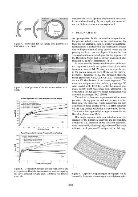
Figure 6. Motivation for the flexure tests performed at<br />
UPC (Gettu et al., 2004).<br />
Figure 7. Configuration <strong>of</strong> the flexure test (Gettu et al.,<br />
2004).<br />
Figure 8. Comparison between the numerical curves and<br />
the experimental load displacement (a) and load-crack opening<br />
(b) curves obtained by Gettu et al., (2004) for two different<br />
materials.<br />
1108<br />
concerns the crack opening displacement measured<br />
in the mid-section (Fig. 7); once again, the numerical<br />
curves fit the experimental ones quite well.<br />
4 DESIGN ASPECTS<br />
An open question for the construction companies and<br />
the <strong>precast</strong> industry concerns the reinforcement for<br />
these <strong>precast</strong> elements. In fact, a heavy conventional<br />
reinforcement is undesired in the construction process<br />
due to the placement <strong>of</strong> many curved rebars and for<br />
pouring the fresh concrete. Figure 9 shows the conventional<br />
reinforcement adopted for the <strong>segments</strong> <strong>of</strong><br />
the Barcelona Metro that, as already mentioned, also<br />
included 30 kg/m 3 <strong>of</strong> steel fibers (FF1).<br />
In order to verify the structural behavior <strong>of</strong> the <strong>tunnel</strong><br />
<strong>segments</strong> towards an optimization <strong>of</strong> the reinforcement,<br />
several NLFM analyses were performed<br />
in the present research work. Based on the material<br />
properties described in §2, the damaged plasticity<br />
model provided in ABAQUS 6.4.1 (2003) was adopted<br />
for the FE <strong>simulations</strong> <strong>of</strong> the <strong>tunnel</strong> <strong>segments</strong>. The<br />
numerical analyses were carried out by adopting a 3D<br />
solid model with 4032 first order hexahedral elements<br />
(C3D8-eight node linear brick elements). The<br />
constitutive law for concrete under compression was<br />
assumed according to EC2 (2003).<br />
The actions on the <strong>tunnel</strong> <strong>segments</strong> result from transportation,<br />
placing process and soil pressures in the<br />
final state. The numerical results concerning the high<br />
compression force exerted by the 30 TBM actuators<br />
on the ring during excavation are presented herein.<br />
The service load applied by a single actuator for the<br />
Barcelona Metro was 3 MN.<br />
One single segment with four actuators was considered<br />
for the numerical analyses and its boundary<br />
conditions (i.e. presence <strong>of</strong> the adjacent <strong>segments</strong>)<br />
were simulated by elastic springs whose stiffness was<br />
calibrated with previous FE analyses <strong>of</strong> the full ring.<br />
Figure 9. Caption <strong>of</strong> a typical figure. Photographs will be<br />
scanned by the printer. Always supply original photographs.