INSTALLATION GUIDE • OWNER'S GUIDE - Bulldog Security
INSTALLATION GUIDE • OWNER'S GUIDE - Bulldog Security
INSTALLATION GUIDE • OWNER'S GUIDE - Bulldog Security

Create successful ePaper yourself
Turn your PDF publications into a flip-book with our unique Google optimized e-Paper software.
LOCATING & MAKING CONNECTIONS<br />
ACCESSORY WIRE(S) THAT POWER THE HEATER/BLOWER MOTOR<br />
(+12V in run or on positions) This wire is also in the main ignition<br />
switch harness usually located in the steering column. Make all connections<br />
as close to the ignition switch harness as possible.<br />
Most vehicles will have (1) accessory wire; however some Fords, newer<br />
GM vehicles and Chrysler 94 and up will have (2) or more accessory<br />
wires. To locate these wire(s) probe for wire(s) that only show +12V<br />
when the ignition switch is in the RUN or ON positions. This wire(s)<br />
will not show +12V when the ignition switch is in any other position.<br />
1. If your vehicle has only (1) accessory wire connect the<br />
WHITE WITH BLACK STRIPE wire from the 4-relay harness<br />
to this wire.<br />
2. If your vehicle has 2 Accessory wires (some GMs and most<br />
Fords), connect the WHITE WITH BLACK STRIPE wire to both<br />
the Accessory #1 and Accessory #2 wires. At this time,<br />
if you do not use the second WHITE wire from the 4-relay<br />
harness (your vehicle does not have an Ignition #2 wire)<br />
you can take that second WHITE wire and attach it to<br />
the Accessory #2 wire, this way you do not have to tie<br />
both the Accessory #1 wire and Accessory #2 wires together<br />
on the WHITE WITH BLACK STRIPE wire from the 4-relay<br />
harness.<br />
STARTER/CRANK WIRE (+12V in the start position only)<br />
Make all connections as close to the ignition switch harness as possible.<br />
The starter/crank wire is also in the main harness. Locate the wire<br />
that shows +12V only in the crank position. This wire will not show<br />
+12V in any other position. Attach the YELLOW WITH BLACK STRIPE wire<br />
from the 4-relay harness to this wire. NOTE: Some vehicles use 2<br />
Starter/Crank wires (mostly Nissan and Audi) in this case connect BOTH<br />
of the Starter/Crank wires from the ignition switch harness to the<br />
YELLOW WITH BLACK STRIPE wire from the 4-relay harness.<br />
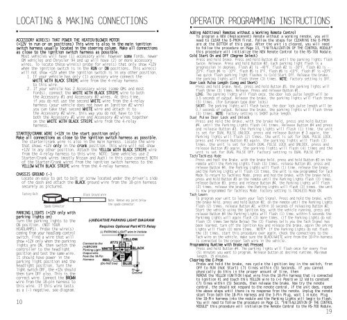
CHASSIS GROUND (-)<br />
Locate an easy to get to bolt or screw located under the driver’s side<br />
of the dash and attach the BLACK ground wire from the 18-pin harness<br />
securely as pictured.<br />
10<br />
Factory Bolt<br />
Spade Connector<br />
PARKING LIGHTS (+12V only with<br />
parking lights on)<br />
Turn the parking lights to the<br />
ON position. (NOT YOUR<br />
HEADLAMPS). Probe the wire(s)<br />
coming from your headlamp control<br />
switch. Find a wire that will<br />
show +12V only when the parking<br />
lights are ON, then switch the<br />
controller to the headlight<br />
position and test the same wire.<br />
It should have power in the<br />
parking light position and the<br />
headlight position. Turn the<br />
light switch OFF, the +12v should<br />
then turn OFF also. This is the<br />
correct wire. Connect the BROWN<br />
wire from the 18-pin harness to<br />
this wire. If this wire tests<br />
as a (-) negative, see diagram.<br />
Black Ground Wire<br />
Note: Remove any paint below<br />
the spade connector.<br />
OPERATOR PROGRAMMING INSTRUCTIONS<br />
Adding Additional Remotes without a Working Remote Control<br />
To program a NEW (Replacement) Remote without a working remote, you will<br />
need to CLEAR the E-PROM first. Follow the steps for CLEARING the E-PROM<br />
are at the BOTTOM of this page. After the unit is cleared, you will need<br />
to follow the procedure on Page 13, "INITIALIZATION OF THE CONTROL MODULE"<br />
this procedure will initialize the NEW Remote Control to the RS-700 Module.<br />
Cold Start On and Off (Degree Select)<br />
Press and hold brake. Press and hold Button #2 until the parking lights flash<br />
twice. Release. Press and hold Button #2. Each parking light flash is a<br />
progression in degrees. Flash #1 is -40ºF, flash #2 is -30ºF, flash #3 is -<br />
20ºF, flash #4 is -10ºF, flash #5 is 0ºF, flash #6 is +10ºF, flash #7 is +20ºF.<br />
Two quick flash parking light flashes is Cold Start Off. Release the brake,<br />
the parking lights will flash three (3) times. NOTE: Factory setting is OFF.<br />
Door Lock Pulse Length (Long and Short)<br />
Press and hold brake. Next, press and hold Button #3, the parking lights will<br />
flash three (3) times. Release. Press and release Button #1.<br />
LONG: The parking lights will flash once, the door lock pulse length will be<br />
3.5 seconds of output. Release the brake, the parking lights will flash three<br />
(3) times. (For European type door locks)<br />
SHORT: The parking lights will flash twice, the door lock pulse length will be<br />
0.7 seconds of output. Release the brake, the parking lights will flash three<br />
(3) times. NOTE: Factory setting is SHORT pulse length.<br />
Dual Pulse Door Lock and Unlock<br />
Press and Hold the Brake, with the brake held, press and hold Button<br />
#4, until the Parking Lights flash (4) times. Release Button #4 and press<br />
and release Button #3, the Parking Lights will flash (1) time, the unit<br />
is set for DUAL PULSE UNLOCK, press and release Button # 3 again, the<br />
Parking lights will flash (2) times, the unit is set for DUAL PULSE LOCK,<br />
press and release Button #3 again, the parking lights will flash (3)<br />
times, the unit is set for both DUAL PULSE LOCK and UNLOCK, press and<br />
release Button #3 again, the parking lights will flash (4) times and the<br />
unit is set for DUAL PULSE OFF. Factory setting is DUAL PULSE OFF.<br />
Tach/Tachless Mode<br />
Press and hodl the Brake, with the brake held, press and hold Button #3 on the<br />
remote until the Parking Lights flash (3) times, release Button #3, press and<br />
release Button #4, the Parking Lights will flash (1) time, release the brake<br />
and the Parking Lights will flash (3) times, the unit is now programmed for Tach<br />
Mode.To return to Tachless Mode, press and hod the brake, with the brake held,<br />
press and hold Button #3 on the remote until the Parking Lights flash (3) times,<br />
release Button #3, press and release Button #4, the Parking Lights will flash<br />
(2) times, release the brake, the Parking Lights will flash (3) times, the unit<br />
is now programmed for Tachless Mode. Factory setting is TACHLESS Mode ON.<br />
Tach Learn<br />
To program your unit to learn your Tach Signal, Press and hold the brake, with<br />
the brake held, press and hold Button #2, on the remote until the Parking Lights<br />
flash (2) times, release Button #2, within 10 seconds of releasing Button #2,<br />
Start the vehicle using the Ignition Key, with the vehicle running, press and<br />
release Button #4 the Parking Lights will flash (1) time, within 5 seconds the<br />
Parkinmg Lights will again flash (3) more times, (if the Parking Lights do not<br />
flash (3) times See Note Below) The (3) flashes tells you the Tach Signal has<br />
been learned, turn off the Ignition Key and release the brake, again the arking<br />
Lights will flash (3) more times. NOTE* If the Parking Lights do not flash<br />
the (3) times, start this procedure over again, check the connections to the<br />
Tach wire on the vehicle, make sure the BLACK/WHITE wire from the 18-Pin harness<br />
is connected to the proper Tach wire in the vehicle.<br />
Programming Runtime with Brake not Pressed<br />
Press and hold Button #4. The parking lights will flash once for every five<br />
(5) minutes you want to program. Release button at desired runtime. Maximum<br />
length, 15 minutes.<br />
Clearing the E-Prom<br />
Press and hold the brake, now cycle the ignition key in the switch, from<br />
OFF to RUN (Not Start) (7) times within (5) Seconds. If you cannot<br />
physically do this in the proper amount of time, then<br />
REMOVE the YELLOW IGNITION Input wire from the 18-Pin harness that is connected<br />
to Ignition #1 and touch this YELLOW wire to (+) Positive 12 Volts constant<br />
(7) times within (5) Seconds, then release the brake. Now try the remote<br />
control, the should not respond to the remote control, if the unit does, repeat<br />
the above steps until there is no response from the remote. Unplug the remote<br />
start from both the 18-Pin Harness and the 3-Pin Plug, wait 1 minute. Plug<br />
the 18-Pin harness into the module and the Parking Lights will begin to flash.<br />
You will need to follow the procedure on Page 13, "INITIALIZATION OF THE CONTROL<br />
MODULE" this procedure will initialize the Remote Control to the RS-700 Module.<br />
19