am - Hanford Site
am - Hanford Site
am - Hanford Site
You also want an ePaper? Increase the reach of your titles
YUMPU automatically turns print PDFs into web optimized ePapers that Google loves.
C,<br />
V1<br />
Iv<br />
W 1C<br />
Vedficallon a,lda<br />
tip n Design Document<br />
+ Requirement<br />
Number I<br />
Source Requirement Text<br />
R - Rev iew<br />
A - Analysis<br />
Reference<br />
(1Nhers is this requirement<br />
T • Test Incorporated in the design)<br />
L.<br />
..<br />
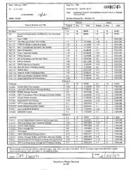
1025 5.7.1 Fans shall be selected on the basis of detailed system pressure loss calculations, and shall be capable of producing the specified design flow<br />
rates. The system designer shall, in accordance with AMCA 201, prepa re a system characle ristc curve for design and limiting conditions under<br />
which il •e fans wit be re^tilled too erase.<br />
1026 5.7.1 Alf resistances in the system, including clean and di rty component p ressure drops (as well as test pressure differen tial), fuli•open and intermediate<br />
co nt ro l d<strong>am</strong>per positions. duct inlet losses, and losses in ducts, housing inlets and outlets, and fan I nlets and outlets shall be considered in the<br />
estimate of the system characteristics. A set of constant speed fan pe rformance cu rv es, showing the static or total pressu re, corresponding<br />
efficiency, capacity, and braKe horsepower shall be obtained from the fan manufacturer for each fan configuration. Fan inlet and discharge<br />
f<br />
configurations, or other system characte ristics, that would adve rsely alter the published fan pe r ormance shall be avoided. Fan size shall be chosen<br />
after performing an analysis of the system characteristic and fan pe rformance cu rv es, conside ri ng all system fa ctors including temperature,<br />
pressure, requi re d airflow and, panicularly for fans operating in pos t-acciden t p ri ma ry containment atmospheres, density and viscosity of the air or<br />
air-ste<strong>am</strong>-entralned water mixture.<br />
1027 5.7.7 Fan selection shall also allow for test conditions in accordance with ASME AG-1, Section TA. The system designer shall Identify the maximum<br />
aLowable di ff<br />
erential<br />
pressure foreach fi lter Dank plus a margin to accommodate filter basing which may occur p ri or to the next su rveillance (typically 25% of the<br />
coincident dirty filter differential pressure). The fan and system characte r istic cu rves shall be included in the system documentation. The fan shall<br />
be selected to operate on the stable po rt ion of Its pressure cu rve under all operating conditions. Provision shall be made in the design to maintain<br />
stable operation under the design flows and va rying pressure range. Inlet vanes, i nlet/outlet d<strong>am</strong>per modulation, variable speed fan cont ro l are<br />
ceritalble le alte rn .., ,.<br />
atives.<br />
^'^'; ' £;.<br />
.. ...<br />
? ...'3,'8. .. , FAN'•QRIVEB .»"r<strong>am</strong>: ^ ... ,^..<br />
ar. u'i ^'f^..Ln < k 4ry i ^^•`^^S+)i",+^ t`<br />
M a^^ ` k , >....,,.., ^ /',z.,. 'x.z..,..,. 1 :ti r .,.. zz^ls^.: -;^ :+ v ar % r, .,. x'41 •"=9 ;^t^s:„ /;,.<br />
I<br />
":'fxr>^3!?:,:., ii ...w.r><br />
1028 Fan drives shall meet the requirements of ACME AG-1, Section BA.<br />
1C29 5.8.1 integral Horsepower Motors •- General:<br />
Moto rs shall comply w4h and be tested and rated in accordance with applicable requirements of NEMA MG1, and IEEE 112A. Pe rformance snail<br />
be ve rifi ed by either lest or ce rt ification as specified for each requ irement. Rated se rvice factor shat; be a minimum of 1.0 unless specified<br />
1030 5.8.1<br />
otherwise,<br />
Motors shall be sized to supply maximum mechanical load demand without exceeding the rated horsepower under all iderltlfied operating<br />
conditions and to produce the required torque and acceleration as re quired by the driven equipment under the most adverse voltage, frequency and<br />
conditions s eci f.ed and shall be desi gned for the starting sequence specified by the Engineer.<br />
1031 5.6.2 Drives for ESF Systems:<br />
Drives In Enginee red Safety Feature (ESF) systems shall comply with Institute of Elect ri cal and Elect ro nic Engineers (IEEE) 323. In addition,<br />
drives of ESF systems located ; s da xMainmen! show! be qua!if^ed in "<br />
anroRl anre with IEEE 334.<br />
ESF fan drives shall be qualified in accordance with IEEE 344. Motor suppo rts and hange rs shall be designed 10 withstand al! seismic and<br />
a g<br />
.,,l .nro i<br />
N a,. S8r<br />
operatinq loads with Y motor in its normal o eratin<br />
^: DAMPERS r<br />
`. z^ Yf<br />
orientation without impairment of o era In<br />
1§ r" ^i<br />
,.-. 4`a %a ; y, > c. $,a<br />
chara tenstics"<br />
r ..<br />
s Y<br />
f'..<br />
1032<br />
".:.<br />
5.9<br />
5.'f l)^<br />
O<strong>am</strong> ors shall meet retheM viremeof '` ASME ....: AG •t, Se ..a lion ^. DA. .<br />
.,...., . •. ,..T'^ '. ., :...<br />
r-^<br />
.. .:r~ ...'/<br />
•. .. .. ...<br />
y.ft" QU) , r's? + F ;':;a x ^Y ^v s .^: „^ . v..V ;<br />
1035 7.1 Drawings:<br />
Complete air-cleaning system layout drawings showing the location of housing, ducts, tan d<strong>am</strong>pe rs, and the other exte rn<br />
al co mponents In each of<br />
three mutually perpendicular planes shall be prepa re d prior to the sta rt of erection. Drawings shall show all connections, hangers, and anchors, the<br />
location and joint details for all welds, and the p rocedure speci fication for each weld. The layout drawings shall reference dimension and shop<br />
drawings of components, as applicable. Layout shall be checked for inte rferences with other items to be Installed in the area, and conflicts shall be<br />
resolved before instatlaUOn.<br />
1036 7.2 Erection:<br />
All ducts, housings, fans, d<strong>am</strong>pers, hangers, anchors, and se rvices (electrical, ste<strong>am</strong>, drains, etc.) shall be installed in st ri ct conformance with the<br />
i<br />
layout drawings; deviations of more than the design tolerance from the loca t on In any plane from the position shown in the drawings shall be<br />
approved by the system designer or other responsible Engineer, and shall be documenled by'as•built drawings.' Prefabricated duct<br />
subassemblies should be made as large as practicable to minimize field joints and field welding. Housings shall rot be used to suppo rt other<br />
"„ uipmemt of the facility for which it was rot designed: `field runs of pipe, dud, or conduit or other systems of the facility shall not be permitted to<br />
penetrate the housing. Inte rnal components (filters, acsorbers, etc.) shall not be installed until immediately before the system is presented for<br />
testing. and shall not be removed from their canons or crates until they are ready to be Installed. The recommendations for handling and installation<br />
lof<br />
HEPA filters riven in ASME AG-1, Section FC shall be oodles with<br />
Date Printed: 21 .09C-04 Ex<strong>am</strong>ple ASME AGO Compliance Mat ri x Page 1 OD of 110<br />
I<br />
r<br />
b<br />
N<br />
A


