am - Hanford Site
am - Hanford Site
am - Hanford Site
You also want an ePaper? Increase the reach of your titles
YUMPU automatically turns print PDFs into web optimized ePapers that Google loves.
C",<br />
tit<br />
t<br />
N<br />
i I, I<br />
VerificationNalida,<br />
tion Design Document<br />
Requirement<br />
Number<br />
Source<br />
I<br />
Requirement Tezt<br />
•Review<br />
A • Analysis y<br />
Reference<br />
(When Is this requirement<br />
T • Test I incorporated In the design)<br />
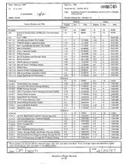
1070 6.2 .2 Duct and Mousing Leak Tests:<br />
Ducts and housings shall be pressurized to determine leak tightness, If the measured leakage is in excess of the acceptance Cmena, the ieaks<br />
should be located by one of the rnetnods listed in pans. 6.5.4 or 6.5.5. A fter ! y aks a re repaired, the housing or duct shall be retested.<br />
1071 63 Prerequisites:<br />
Construction, modifications, and repairs affecting the lest bounda ry stall be complete and the inlet and discharge openings of the duct or housing<br />
sealed before the lest is sta rted. All electrical, piping, and instrument connec tions shall be complete and all permanent seals installed before the<br />
1 .: , .. ^.-.a<br />
4.,w<br />
test is started.<br />
APPARATUS rn... 1'Y<br />
R -: s t^ S.>^,'x''. r ,F,."' ". -3a'v l? ^s.^?;;c 4,^a t YX i .s.6+i i....c i -.i ^, rt r'4''£'+^ " z „r`S, ;r, d 1<br />
,<br />
.<br />
_<br />
n'J. ^^ .. ),. •"n .rr..0 +•^. ,':^i ;:•C rti<br />
STRUCTURAL'CAPABILITY TEST..';<br />
;, ; , ^^ 1 , s f ` ' x, ? ..<br />
1072 6A.1.1 Test tan with Cow control,<br />
1073 .4.1.2 Covers to seal test boundaries.<br />
1074 6.4,1 .3 Clock or timer accurate to ''- 1.0 sec.<br />
4<br />
1075<br />
/;i,<br />
6.4.1.4 Pressure Indlcad Cevice'accur to to +/-0.1 in w.<br />
•c.-<br />
- :<br />
43:':- : D11C7%A1JD HDCJSING!'LEAK RATS J7 ST '"<br />
.a 7 s.c y ,.1. r•, Yd 'Y' Ai?x rir 3y(` >'. *oi, v,:<br />
1 076 6. 4 .2.1 Test fan with now Control.<br />
1077 6.4.22 Flowmeter or totalt as volume meter accurate to . +-5h c' reading.<br />
1076 .4,2.3 'em erature Indicating device accurate t N• 5 de grees F.<br />
1079 6.4.2.4 Pressure imclicaling deice accurate to +/- 0 1 in w,<br />
i060 6.4.2.5 Covers to seal test boundaries.<br />
1081 1 6A.2.5 Clock ortmer accurate to +/- 1.0 sec.<br />
1062 I 6.4.3 Bubble Method:<br />
Bubble solution in a plastic squeeze-type laborato ry wash bottle (a commercial test solution or a so lution consisting of equal pa rts liquid<br />
deter ent glycerin. and water).<br />
1083 6.4,4 Audible Leak Method:<br />
Suitable electronic sound detection a ut merit (optional).<br />
t' +?.. ':<br />
,^" '8<br />
5 3'•. .RDCEDU RE srw ..+ yr 5 :+_ g f+?s^<br />
^^ is<br />
Nc^<br />
777777<br />
toF c y<br />
p x s r'vtk;<br />
vow.- 9 a' `'m 4^"g<br />
/. ,,r.6.S.7_ .i' F i^2 STRUCTURAL'CAPABICITYTEST. -:• ;:i4` rr+., ..< ^f. l J r ^}'Y _'t.<br />
r . y : ;wzS ^ ...,.<br />
1"<br />
rr.,'^:;, !? . ;ek.yYnt 1 /'<br />
r;..,,:." ,^^.,..<br />
Y .11. :ir<br />
1084 6.5.1,1 Connect Vi e rest fan wile, now control to the housing and /or ductino.<br />
1085 6.5.1.2 Install a pressure indicating O ev ice so that it will indicate the pressure Inside the duct and/or ho usjnq bei . tested. I<br />
1066 6.5.1.3 Saal lest boundaries and dose acce6s openings In the normal manner.<br />
1087 $.5.1.4 Start the fan and operate until the strut r { capability pressure is achieved Maintain pressire for the duration of the i inspection<br />
1088 6.5 1.5 Inspect the pressure boundary for distortion or breach of integrity.<br />
1089<br />
xe<br />
t<br />
6.5.1.6<br />
c.<br />
Releas pressure and Ins ect for erman,nt tlistortion<br />
DGC'>PAhJC.HO.USIh1G LEf ►1C. T;E€PEST: C`ONSTAIJT-FRES'SURE ME7NbD fy `r « X55:. 1..^ ' : ^lx^S.- #a<br />
A ? ^ ;" M<br />
1090 6.5.2.1 Connect the test fan with flow control to the housing and !of ducting.<br />
the housing (downstre<strong>am</strong> of the throtillng valve if used<br />
Connect the Ctowmeler or lotallzing gas volume meter between the fan and<br />
1091 6.5.2.2 Install temperature and pressure devices to incicaie representative temperature and pressure ins;de the duct andlor housing oeing tested.<br />
032 6.5.2.3 Seal test boundaries and close access openings in the normal manner. Do not use tempora ry sealants, duct tape, or similar tempora ry mate ri als<br />
except fors alln and !emporary b lankoffs.<br />
1093 6.5.2.4 Start the fan and operate until the maximum o perating pressure is achieved, Maintain pressure constant with a flow cont ro l device until the<br />
temperature remains on sla n t wilMn •/-0,5 decrees F for a minimum of 10 min.<br />
1094 6.5.2,5 Measure the flow rate of the air being added to or removed from the duct/housing while maintaining the maximum operating p re ssure w.thin +i-<br />
0.1 in, w.g. The now rate should be measu red oy one of the following methods.<br />
a) For a flowmeter: record Cow readings once a minute for a 10 min continuou s_ pe riod and average the readin g s to calculate the measured<br />
akage Cow rate.<br />
b) For a totalizing gas volumemeter, measure the total volume of air for a 10 min continuous peroc anddivide the measured volume by time (10<br />
ti9ri) to calculate the measured leaks a now rate.<br />
1095 6.5.2.6 If the calculated leak rate exceeds the acceptance value, repo rt to the owner and locate the leaks in accordance with para. 5.5.4 and for para.<br />
fi..5 R air and re'est as •e wired,<br />
77 v 's; 4'x..5,3 x, D^1C7'A?1D.:XiO.l7SlIJG1 A C RAfiVPEST ° P,,RESSUFtE'DECAY4tUlETi iOb Y y rfi.,,: . G °-' FV^, '.... .4t ,. . .°'


