Casing Design Hand Calculation - George E King Engineering
Casing Design Hand Calculation - George E King Engineering
Casing Design Hand Calculation - George E King Engineering

Create successful ePaper yourself
Turn your PDF publications into a flip-book with our unique Google optimized e-Paper software.
• What casing size?<br />
<strong>Casing</strong> <strong>Design</strong><br />
– Set by Pump, Packer, Tubing Requirements and<br />
Limited by meeting pressure and economic objectives.<br />
• Where is the largest tubing? The casing has to<br />
accommodate the tubing.<br />
• Are kickoffs planned? – what size tubular is in the kickoff?<br />
• What about pump and other equipment needs – and sizes….<br />
• How many casing strings are needed to make depth?<br />
• A casing string is designed from the bottom to<br />
the top and from the inside to the outside.<br />
3/14/2009<br />
<strong>George</strong> E. <strong>King</strong> <strong>Engineering</strong><br />
GEK<strong>Engineering</strong>.com<br />
1
Slim Hole Wells<br />
• Slim hole wells are often drilled and<br />
completed to try to meet economic goals.<br />
• From completion, stimulation, reliability, lift<br />
and workover considerations, a slim hole well<br />
is often the very worst choice.<br />
• Choose wisely!<br />
3/14/2009<br />
<strong>George</strong> E. <strong>King</strong> <strong>Engineering</strong><br />
GEK<strong>Engineering</strong>.com<br />
2
<strong>Casing</strong> <strong>Design</strong> Example<br />
• Simple hand-worked design using collapse,<br />
burst and tensile in the design.<br />
• First example – a multiple weight/grade pick<br />
to show where strength is required – avoid<br />
this design in the real world if possible.<br />
• Second – calculation of a single pipe weight<br />
and grade that can be used.<br />
NOTE - This example problem is not intended to teach casing design, nor is it a<br />
replacement for modern casing design methods. More modern equations (e.g., API<br />
equations) are available as are a variety of computer simulations that are much more<br />
<strong>George</strong> E. <strong>King</strong> <strong>Engineering</strong><br />
accurate that this approximation.<br />
3/14/2009 3<br />
GEK<strong>Engineering</strong>.com
Buoyancy – brine offsets part of all of<br />
W b = W a (1 – ρ f / ρ s)<br />
the pipe weight<br />
W b = buoyed weight of casing in a fluid<br />
W a = air weight of casing<br />
ρ f = density of fluid, lb/gal<br />
ρ s = density of steel = 65 lb/gal<br />
3/14/2009 4<br />
<strong>George</strong> E. <strong>King</strong> <strong>Engineering</strong><br />
GEK<strong>Engineering</strong>.com
Simple Buoyancy Example<br />
• 10,000 ft string, 7”, 26 lb/ft, 12 lb/gal mud<br />
• Wair = (10,000 ft) (26 lb/ft) = 260,000 lb<br />
• W buoyed = (260,000 lb) (1- (12/65.4)) =<br />
= 212,294 lb<br />
• For larger pipe strings and heavier brine, the<br />
effect of buoyancy is increased. Very large pipe in<br />
heavy brine can actually float.<br />
3/14/2009 5<br />
<strong>George</strong> E. <strong>King</strong> <strong>Engineering</strong><br />
GEK<strong>Engineering</strong>.com
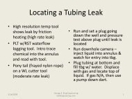
Mud in Hole<br />
Mud in Csg<br />
212,300 lb<br />
3/14/2009<br />
Calculated Hook Load Changes<br />
Mud in Hole<br />
Cmt in Csg<br />
283,600 lb<br />
Cmt in Hole<br />
Cmt in Csg<br />
195,600 lb<br />
<strong>George</strong> E. <strong>King</strong> <strong>Engineering</strong><br />
GEK<strong>Engineering</strong>.com<br />
Cmt in Hole<br />
Water in Csg<br />
65,936 lb<br />
6
Downhole Causes of Axial<br />
Compression<br />
• Sources of Axial Compression:<br />
– Buoyancy – before cement sets<br />
– Poisson’s effect – if casing is landed or sticks<br />
– Reverse ballooning – too much outside pressure<br />
– Thermal expansion – only if both ends fixed<br />
– Borehole friction – deviated holes and doglegs<br />
– Drag – same as friction in most cases<br />
– Slack-off – same as landing<br />
3/14/2009 7<br />
<strong>George</strong> E. <strong>King</strong> <strong>Engineering</strong><br />
GEK<strong>Engineering</strong>.com
Axial (Tensile) Force versus Depth in a<br />
<strong>Casing</strong> String<br />
• 12,000 ft, 9-5/8”, 53.5 lb/ft casing (0.545 wall),<br />
suspended in 16 lb/gal mud.<br />
• W a = (12,000 ft) (53.5 lb/ft) = 642,000 lb<br />
• W buoyed = (642,000 lb) (1- (16/65.4)) =484,935 lb<br />
• Buoyancy force = 642,000 – 484,935 = 157.065 lb<br />
3/14/2009 8<br />
<strong>George</strong> E. <strong>King</strong> <strong>Engineering</strong><br />
GEK<strong>Engineering</strong>.com
Weight<br />
Buoyancy<br />
Surface<br />
Neutral point is a<br />
calculated position<br />
on the pipe that<br />
shows offset of<br />
string weight by<br />
buoyancy.<br />
Wa<br />
- 0 +<br />
Wt on pipe at depth<br />
<strong>George</strong> E. <strong>King</strong> <strong>Engineering</strong><br />
3/14/2009 9<br />
GEK<strong>Engineering</strong>.com<br />
Wb
Buoyancy Neutral Point – remember – this is a calculation aid, not a real<br />
point in the well.<br />
1. <strong>Casing</strong> below the neutral point is considered to be in “compression”<br />
for the purposes of the calculations and collapse forces dominate the<br />
casing strength design.<br />
2. <strong>Casing</strong> above the neutral point is in tension and burst strength<br />
dominates the design. However, casing in tension must be derated<br />
for the effect of tension on collapse rating.<br />
3/14/2009 10<br />
<strong>George</strong> E. <strong>King</strong> <strong>Engineering</strong><br />
GEK<strong>Engineering</strong>.com
Collapse <strong>Design</strong> – Be careful, this type of<br />
design considers only initial, static froces<br />
and does not consider dynamic, production<br />
and thermal forces<br />
Pcx = 0.052 ρ f Dx<br />
Pcx = collapse pressure exerted by the mud at a depth Dx<br />
ρ f = density of mud, lb/gal<br />
Dx = depth<br />
With this formula a collapse pressure at an estimated depth is calculated<br />
(safety factor has not been applied yet).<br />
3/14/2009 11<br />
<strong>George</strong> E. <strong>King</strong> <strong>Engineering</strong><br />
GEK<strong>Engineering</strong>.com
<strong>Casing</strong> <strong>Design</strong> Example – Note – this is the old<br />
method that uses multiple picks of string weight and<br />
grade – it is useful for showing how a simple design<br />
works, but many pipe grades and weights would create<br />
confusion at the well during casing running.<br />
<strong>Design</strong> a 10,000 ft string of 7” casing.<br />
Pore pressure = 8000 psi at 10,000 ft.<br />
Mud weight = 16.3 lb/gal.<br />
Frac gradient = 0.9 psi/ft.<br />
Convert to gradients:<br />
Pore pressure = 8000/10,000 = 0.8 psi/ft<br />
Mud weight = 16.3 lb/gal * (0.052) = 0.85 psi/ft<br />
Frac gradient = 0.9 psi/ft<br />
<strong>George</strong> E. <strong>King</strong> <strong>Engineering</strong><br />
3/14/2009 12<br />
GEK<strong>Engineering</strong>.com
Calculate the “Theoretical” Buoyancy Neutral Point.<br />
N.P. = Dx (1- (fluid density/steel density)<br />
= 10,000 ft (1 – (16.3/65.4)<br />
= 7500 ft<br />
This is the equivalent amount of the string weight at the<br />
surface. If a heavier fluid was used, the N.P. would be<br />
shallower in the well (more of the pipe weight would be<br />
offset by the buoyancy).<br />
3/14/2009 13<br />
<strong>George</strong> E. <strong>King</strong> <strong>Engineering</strong><br />
GEK<strong>Engineering</strong>.com
Maximum Collapse Force<br />
Pcx = (10000 ft) * (0.85 psi/ft) = 8500 psi<br />
Since it is a force and not a rating, the safety factor is multiplied:<br />
Pcx = (8500) * (1.1) = 9350 psi<br />
Now, select a pipe with a collapse pressure minimum that will handle<br />
the load…. No need to derate the pipe number, the safety factor has<br />
already been applied on the force (or load).<br />
First pick… 7”, 32 lb/ft, C-95, Pc = 9730 psi.<br />
This is the bottom joint – there is less strength required as the<br />
strength analysis comes up the well – until it nears the top. The<br />
strength required is maximum at the bottom (collapse is maximum)<br />
and at the top (burst is maximum).<br />
Although this method would lead to many different weights and<br />
grades, the best approach is a single selection of strong casing.<br />
<strong>George</strong> E. <strong>King</strong> <strong>Engineering</strong><br />
3/14/2009 14<br />
GEK<strong>Engineering</strong>.com
<strong>Casing</strong> Strength Pick<br />
• Start with a casing of the right alloy, and select<br />
the first pick in the middle of the range.<br />
Weight,<br />
lb/ft<br />
Collapse,<br />
psi<br />
Grade<br />
23 4150 C-95<br />
26 5870 C-95<br />
29 7820 C-95<br />
32 9730 C-95<br />
35 11,640 C-95<br />
28 13,420 C-95<br />
<strong>George</strong> E. <strong>King</strong> <strong>Engineering</strong><br />
3/14/2009 15<br />
GEK<strong>Engineering</strong>.com
Next, select a lower strength string…<br />
Pick 7”, 29 lb/ft, C-95, Pc = 7820 psi<br />
Pcx = 7820/1.1 = 7109 psi collapse strength<br />
How deep can it be set?<br />
Depth = 7109 psi/0.85 psi/ft = 8360 ft<br />
3/14/2009 16<br />
<strong>George</strong> E. <strong>King</strong> <strong>Engineering</strong><br />
GEK<strong>Engineering</strong>.com
Set Point – for the 32 lb/ft top<br />
• The bottom of the 29 lb/ft sets the top of the<br />
32 lb/ft. Note – the 32 lb/ft string can be run<br />
higher but the 29lb/ft is theoretically cheaper<br />
and lighter.<br />
• The 32 lb/ft runs from 8360 to 10,000 ft.<br />
3/14/2009 17<br />
<strong>George</strong> E. <strong>King</strong> <strong>Engineering</strong><br />
GEK<strong>Engineering</strong>.com
Select a third string…..<br />
7”, 26 lb/ft, C-95, Pc = 5870 psi<br />
Safety factor = 1.1, Pcx = 5870/1.1 = 5330 psi<br />
Set depth = 5330/0.85 = 6270 ft<br />
Neutral Point = 7500 ft – since this depth is above the<br />
N.P., the calculations switch to burst design rather<br />
than collapse design.<br />
Deration of the collapse for tension effects is common<br />
– use 4% deration as a starting point, but the final<br />
effect is usually between 1% and 2% except in<br />
extreme cases.<br />
3/14/2009 18<br />
<strong>George</strong> E. <strong>King</strong> <strong>Engineering</strong><br />
GEK<strong>Engineering</strong>.com
Effect of axial loads on collapse and burst<br />
<strong>Casing</strong> in tension is weaker<br />
in collapse and stronger in<br />
burst – consider it for<br />
collapse calculations.<br />
<strong>Casing</strong> in compression is<br />
weaker in burst and stronger<br />
in collapse – ignore it for<br />
collapse calculations.<br />
3/14/2009 19<br />
<strong>George</strong> E. <strong>King</strong> <strong>Engineering</strong><br />
GEK<strong>Engineering</strong>.com
Derate for collapse:<br />
1. Derate maximum depth by 4% (this is an experience estimate, the<br />
correct value is usually between 2% and 4%).<br />
2. Calculate unit tensile stress:<br />
St = (7500 ft – 6020 ft) * 26 lb/ft = 38480 lb<br />
3. Axial load factor = (unit tensile stress/tensile body strength)<br />
= (38480 / 717,000) = 0.054<br />
4. Derating factor (from deration tables for casing) = 0.985<br />
5. Pc = (5330 psi)(0.985) = 5280 psi<br />
6. Collapse check = (5250 / 0.85) = 6176 ft,<br />
first guess of 6020 ft is OK.<br />
3/14/2009 20<br />
<strong>George</strong> E. <strong>King</strong> <strong>Engineering</strong><br />
GEK<strong>Engineering</strong>.com
<strong>Design</strong> to this point:<br />
Interval Weight Grade<br />
10,000’ to 8360’ 32 lb/ft C-95<br />
8360’ to 6020’ 29 lb/ft C-95<br />
6020’ to ? 26 lb/ft C-95<br />
Since the depth is now above the buoyancy neutral point, burst becomes<br />
the basis for design.<br />
<strong>George</strong> E. <strong>King</strong> <strong>Engineering</strong><br />
3/14/2009 21<br />
GEK<strong>Engineering</strong>.com
Safety Factors<br />
Safety factors used in the calculations vary with the<br />
application. The following as general estimates for this<br />
example. Safety factors must be set by engineering<br />
experts well versed in your application.<br />
• For this problem:<br />
– Collapse – risk: lose a section of the well, safety factor of<br />
1.1 is typical.<br />
– Burst – risk: life endangered justifies a must higher safety<br />
factor, 1.2 to 1.4 is typical.<br />
– Tension – risk: dropping the string. Because of variances in<br />
coupling make-up strength, a safety factor is 1.5 to 1.7.<br />
3/14/2009 22<br />
<strong>George</strong> E. <strong>King</strong> <strong>Engineering</strong><br />
GEK<strong>Engineering</strong>.com
Burst <strong>Design</strong><br />
Worst case– blow out with gas bubble in the hole.<br />
At Surface:<br />
Ps = (0.052 ρ p Dx) – (Gg Dx)<br />
ρ p<br />
= pore pressure equivalent wt., lb/gal<br />
Dx = depth to pay<br />
Gg = Gas gradient, 0.1 psi/ft for this problem<br />
3/14/2009 23<br />
<strong>George</strong> E. <strong>King</strong> <strong>Engineering</strong><br />
GEK<strong>Engineering</strong>.com
Calculate a Surface Pressure Estimate.<br />
Lesser of:<br />
Fracture gradient less a gas gradient<br />
Ps = (0.9 – 0.1)psi/ft * 10,000 ft = 8,000 psi<br />
Formation pressure less a gas gradient (0.1 psi/ft)<br />
Ps = (0.8 – 0.1) * 10,000 ft = 7,000 psi<br />
Use 7,000 psi as maximum surface pressure<br />
3/14/2009 24<br />
<strong>George</strong> E. <strong>King</strong> <strong>Engineering</strong><br />
GEK<strong>Engineering</strong>.com
Now, how shallow can the 26 lb/ft C-95 be set?<br />
Pb = 8600 psi, with safety factor of 1.4<br />
Pb = 8600/1.4 = 6140 psi<br />
Shallowest set depth:<br />
Dx = [(7000 psi – 6140 psi) / (0.8 – 0.1)]<br />
Dx = 1230 ft<br />
26 lb/ft runs from 6020 ft to 1230 ft.<br />
Need a stronger pipe to run to surface…..<br />
3/14/2009 25<br />
<strong>George</strong> E. <strong>King</strong> <strong>Engineering</strong><br />
GEK<strong>Engineering</strong>.com
A stronger pipe must be set to surface….<br />
Select 26 lb/ft, P-110<br />
Pb = 9960 psi, safety factor of 1.4<br />
Pb = 9960/1.4 = 7110 psi<br />
Dx = [(7000 – 7110) / (0.8 – 0.1)] < 0<br />
The P-110 can be run to surface.<br />
3/14/2009 26<br />
<strong>George</strong> E. <strong>King</strong> <strong>Engineering</strong><br />
GEK<strong>Engineering</strong>.com
Why would a multiple weight or multiple<br />
grade casing string be a problem?<br />
• Hard to keep the weight and grades in correct<br />
order – would take much longer to run the<br />
string.<br />
• A multiple inside diameter string would also<br />
create setting problems for packers.<br />
3/14/2009<br />
<strong>George</strong> E. <strong>King</strong> <strong>Engineering</strong><br />
GEK<strong>Engineering</strong>.com<br />
27
<strong>Casing</strong> <strong>Design</strong> Options – think about running and setting packers.<br />
What happens if a<br />
joint of the<br />
heaviest weight<br />
casing (smallest<br />
ID) is accidently<br />
set at the surface?<br />
Mixed<br />
weights,<br />
same<br />
grade<br />
Mixed<br />
grades<br />
and<br />
weights<br />
Monobore:<br />
mixed<br />
grades,<br />
same<br />
weight<br />
<strong>George</strong> E. <strong>King</strong> <strong>Engineering</strong><br />
3/14/2009 28<br />
GEK<strong>Engineering</strong>.com
Tensile Ratings<br />
• Two ratings for tensile rating:<br />
– Body Yield = used in collapse rating calculations<br />
– Joint Yield = used in tensile design<br />
• Connection Strength<br />
– API connection, body stronger than threads<br />
– Premium connections, joint often stronger than body<br />
3/14/2009 29<br />
<strong>George</strong> E. <strong>King</strong> <strong>Engineering</strong><br />
GEK<strong>Engineering</strong>.com
Tension <strong>Design</strong> (just pipe above the “neutral<br />
point shown”), s.f. = 1.7 for the example.<br />
Pipe Length Wt/ft Grade Load<br />
lb<br />
Cummul<br />
ative<br />
lb<br />
Joint Rating<br />
lb<br />
7500 – 6020 ft 29 C-95 42,920 42,920 683,000/1.7 = 487,850<br />
6020 – 1230 ft 26 C-95 124,540 167,460 593,000/1.7 = 348,820<br />
1230 – 0 ft 26 P-110 31,980 199,440 693,000/1.7 = 495,000<br />
3/14/2009 30<br />
<strong>George</strong> E. <strong>King</strong> <strong>Engineering</strong><br />
GEK<strong>Engineering</strong>.com
Final <strong>Design</strong> – multiple casing<br />
Interval, ft Wt/ft Grade Connection<br />
0 – 1230 26 P-110 LT&C<br />
1230 – 6020 26 C-95 LT&C<br />
6020 – 8360 29 C-95 LT&C<br />
8360 – 10,000 32 C-95 LT&C<br />
3/14/2009 31<br />
<strong>George</strong> E. <strong>King</strong> <strong>Engineering</strong><br />
GEK<strong>Engineering</strong>.com
A Better <strong>Design</strong>?<br />
• A simpler approach that yields a reliable<br />
design may be to use one weight and grade of<br />
casing that can handle the forces anywhere in<br />
the well.<br />
• Exceptions:<br />
– Very long strings.<br />
– Corrosion control changes along the well.<br />
– Limitations of rig lifting power,<br />
– Etc.<br />
3/14/2009<br />
<strong>George</strong> E. <strong>King</strong> <strong>Engineering</strong><br />
GEK<strong>Engineering</strong>.com<br />
32
Single String – Quick Look<br />
• Take the 32 lb/ft, 7”, C-95 that was suitable for the<br />
bottom section (collapse resistance).<br />
• Check it against the burst requirement at surface: Pb =<br />
11760 psi / 1.4 = 7685 psi, which is more than the 7,000<br />
psi max Ps – OK<br />
• Check the tensile rating: 768,000 / 1.7 = 451,764 lb<br />
capacity (max string weight was 199, 440.<br />
• The 32 lb/ft., C-95, 7” can be run from bottom to top,<br />
satisfying simple loads of collapse, burst and tensile.<br />
3/14/2009 33<br />
<strong>George</strong> E. <strong>King</strong> <strong>Engineering</strong><br />
GEK<strong>Engineering</strong>.com
Quiz – <strong>Casing</strong> Problem<br />
1. For a 10000 ft deep well, with 9.0 lb/gal mud.<br />
Select a single casing size (minimum 6.1” ID), grade<br />
and weight that can be run to bottom in a 9-1/4”<br />
hole and will withstand the collapse pressure of the<br />
mud to a 1.1 safety factor and the burst pressure<br />
(3600 psi is maximum surface pressure from the<br />
zone, 4600 psi is BHP) to a 1.4 safety factor. Make<br />
assumptions as needed, but record the<br />
assumptions with the solution.<br />
3/14/2009 34<br />
<strong>George</strong> E. <strong>King</strong> <strong>Engineering</strong><br />
GEK<strong>Engineering</strong>.com