Space Weather Monitors SID Users Manual - Stanford Solar Center ...
Space Weather Monitors SID Users Manual - Stanford Solar Center ...
Space Weather Monitors SID Users Manual - Stanford Solar Center ...

You also want an ePaper? Increase the reach of your titles
YUMPU automatically turns print PDFs into web optimized ePapers that Google loves.
<strong>Space</strong> <strong>Weather</strong> <strong>Monitors</strong> <strong>SID</strong> <strong>Manual</strong><br />
62<br />
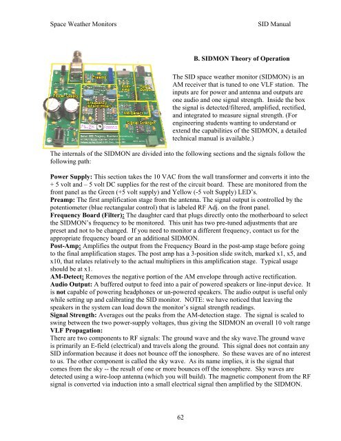
B. <strong>SID</strong>MON Theory of Operation<br />
The <strong>SID</strong> space weather monitor (<strong>SID</strong>MON) is an<br />
AM receiver that is tuned to one VLF station. The<br />
inputs are for power and antenna and outputs are<br />
one audio and one signal strength. Inside the box<br />
the signal is detected/filtered, amplified, rectified,<br />
and integrated to measure signal strength. (For<br />
engineering students wanting to understand or<br />
extend the capabilities of the <strong>SID</strong>MON, a detailed<br />
technical manual is available.)<br />
The internals of the <strong>SID</strong>MON are divided into the following sections and the signals follow the<br />
following path:<br />
Power Supply: This section takes the 10 VAC from the wall transformer and converts it into the<br />
+ 5 volt and – 5 volt DC supplies for the rest of the circuit board. These are monitored from the<br />
front panel as the Green (+5 volt supply) and Yellow (-5 volt Supply) LED’s.<br />
Preamp: The first amplification stage from the antenna. The signal output is controlled by the<br />
potentiometer (blue rectangular control) that is labeled RF Adj. on the front panel.<br />
Frequency Board (Filter): The daughter card that plugs directly onto the motherboard to select<br />
the <strong>SID</strong>MON’s frequency to be monitored. This unit has two pre-tuned adjustments that are<br />
preset and not to be changed. If you need to monitor a different frequency, contact us for the<br />
appropriate frequency board or an additional <strong>SID</strong>MON.<br />
Post-Amp: Amplifies the output from the Frequency Board in the post-amp stage before going<br />
to the final amplification stages. The post amp has a 3-position slide switch, marked x1, x5, and<br />
x10, that relates relatively to the actual multipliers in this amplification stage. Typical usage<br />
should be at x1.<br />
AM-Detect: Removes the negative portion of the AM envelope through active rectification.<br />
Audio Output: A buffered output to feed into a pair of powered speakers or line-input device. It<br />
is not capable of powering headphones or un-powered speakers. The audio output is useful only<br />
while setting up and calibrating the <strong>SID</strong> monitor. NOTE: we have noticed that leaving the<br />
speakers in the system can load down the monitor’s signal strength readings.<br />
Signal Strength: Averages out the peaks from the AM-detection stage. The signal is scaled to<br />
swing between the two power-supply voltages, thus giving the <strong>SID</strong>MON an overall 10 volt range<br />
VLF Propagation:<br />
There are two components to RF signals: The ground wave and the sky wave.The ground wave<br />
is primarily an E-field (electrical) and travels along the ground. This signal does not contain any<br />
<strong>SID</strong> information because it does not bounce off the ionosphere. So these waves are of no interest<br />
to us. The other component is called the sky wave. As its name implies, it is the signal that<br />
comes from the sky -- the result of one or more bounces off the ionosphere. Sky waves are<br />
detected using a wire-loop antenna (which you will build). The magnetic component from the RF<br />
signal is converted via induction into a small electrical signal then amplified by the <strong>SID</strong>MON.