Modular units
Modular units
Modular units

Create successful ePaper yourself
Turn your PDF publications into a flip-book with our unique Google optimized e-Paper software.
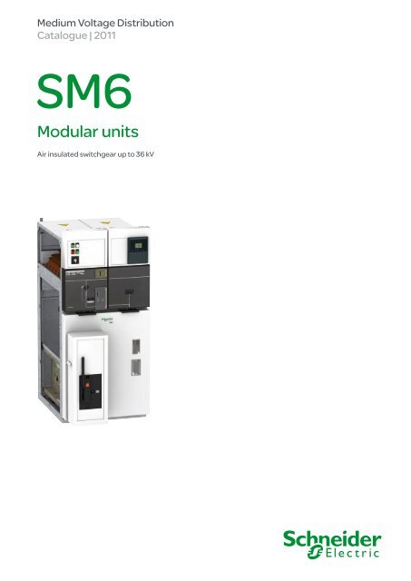
Medium Voltage Distribution<br />
Catalogue | 2011<br />
SM6<br />
<strong>Modular</strong> <strong>units</strong><br />
Air insulated switchgear up to 36 kV
SM6 General contents<br />
AMTED398078EN.indd<br />
Presentation 3<br />
Generalities 11<br />
Characteristics<br />
of the functional <strong>units</strong><br />
43<br />
Connections 83<br />
Installation 91<br />
Appendices<br />
Order form<br />
99<br />
1
2 AMTED398078EN.indd
Presentation Contents<br />
AMTED398078EN.indd<br />
The experience of a world leader 4<br />
The range’s advantages 5<br />
Protecting the environment 6<br />
A full range of services 7<br />
The references of a leader 8<br />
Quality assurance 9<br />
3
MT20140<br />
MT20141<br />
Presentation The experience of a world leader<br />
The Schneider Electric experience’s extends over forty years in factorybuilt<br />
cubicles and over thirty years in SF6 breaking technology for Medium<br />
Voltage switchgear.<br />
This experience means that today Schneider Electric can propose<br />
a complementary range: vacuum type circuit breaker cubicles up to 36 kV<br />
and standard or enhanced internal arc withstand cubicles to reinforce<br />
the safety of people according to the IEC standard.<br />
This gives you the advantage of unique experience, that of a world leader,<br />
with over 2,000 000 SF6 Medium Voltage <strong>units</strong> installed throughout<br />
the world.<br />
Putting this experience at your service and remaining attentive to your<br />
requirements is the spirit of active partnership that we want to develop<br />
in offering you the SM6.<br />
The modular SM6 is a range of harmonised cubicles equipped<br />
with SF6 or vacuum breaking technology switchgear with 30 years<br />
life span.<br />
These cubicles allow you to produce all your Medium Voltage substation<br />
requirements up to 36 kV by superposing their various functions.<br />
The result of in-depth analysis of your requirements, both now and<br />
in the future, SM6 cubicles mean that you can take advantage<br />
of all the features of both a modern and proven technology.<br />
1975: innovation<br />
Sulphur hexafl uoride (SF6) is fi rst used in an MV switch for an MV/LV<br />
transformer substation, with the VM6.<br />
1989: experience<br />
Over 300,000 VM6 cubicles equipped networks throughout the world.<br />
1991: innovation and experience<br />
Cumulated with the second generation of SM6 modular SF6 cubicles.<br />
2010: a leading position<br />
b with over 1,000,000 SM6 cubicles installed around the world,<br />
Schneider Electric consolidates its position as uncontested leader<br />
in the Medium Voltage fi eld.<br />
4 AMTED398078EN.indd
MT20142<br />
MT20143<br />
MT20144<br />
MT20145<br />
MT20146<br />
MT20147<br />
MT20148<br />
Presentation The range’s advantages<br />
AMTED398078EN.indd<br />
Upgradability<br />
SM6, a comprehensive range<br />
b a comprehensive offer covering your present and future requirements<br />
b a design adapted to the extension of your installations<br />
b a catalogue of functions for all your applications<br />
b a product designed to be in compliance with standards constraints<br />
b options to anticipate the telecontrol of your installations.<br />
Compactness<br />
SM6, an optimised range<br />
b compact <strong>units</strong>, with low increment cubicles<br />
b rationalised space requirement for switchboard installation<br />
b reduction of civil works costs<br />
b easy integration in factory-built outdoor substations for which the SM6<br />
is particularly well designed.<br />
Maintenance<br />
SM6, a range with reduced maintenance<br />
b the active parts (breaking and earthing) are integrated in an SF6-fi lled, “sealed for<br />
life” unit<br />
b the control mechanisms, are intented to function with reduced maintenance under<br />
normal operating conditions<br />
b enhanced electrical endurance when breaking.<br />
Ease of installation<br />
SM6, a simple range to incorporate<br />
b reduced dimensions and weights<br />
b only one civil works layout<br />
b a solution adapted to cable connection<br />
b simplifi ed switchboard busbar design.<br />
Ease and safe to operate<br />
SM6, a proven range<br />
b a three position switch to block incorrect switching<br />
b the earthing disconnector has full closing capacity<br />
b positive breaking of position indicators<br />
b internal arc withstand in the cable and switchgear compartments<br />
b clear and animated display diagrams<br />
b switching lever with an “anti-refl ex” function<br />
b compartmented cubicles.<br />
SM6: a range designed with telecontrol in mind<br />
SM6 switchgear is perfectly adapted to telecontrol applications.<br />
Motorised, either when installed or at a later date on-site without<br />
any interruption in service, SM6 combines with the Easergy T200<br />
remote control interface. You therefore benefi t from a ready-to connect<br />
unit that is easy to incorporate providing guaranteed switchgear operation.<br />
SM6: a range with adapted protection devices<br />
With the SM6, Schneider Electric proposes solutions for network management;<br />
the Sepam and VIP or relay ranges protect installations, providing continuity<br />
of electrical supply and reducing downtime.<br />
5
Presentation Protecting the environment<br />
Schneider Electric’s recycling service<br />
for SF6 products is part of a rigorous<br />
management process.<br />
MT55145 61016N<br />
ISO 14001<br />
61051N<br />
Product environmental profi le & recycling service<br />
Schneider Electric is committed to a long term environmental approach.<br />
As part of this, the SM6 has been designed to be environmentally friendly,<br />
notably in terms of the product’s recycleability.<br />
The materials used, both conductors and insulators, are identifi ed in product<br />
environmental profi le analysis and easily separable.<br />
It was performed in conformity with ISO 14040 “Environmental management:<br />
life cycle assessment - principle and framework”.<br />
At the end of its life, SM6 can be processed, recycled and its materials<br />
recovered in conformity with the draft European regulations on the end-of-life<br />
of electronic and electrical products, and in particular withoutany gas being<br />
released to the atmosphere nor any polluting fl uids being discharged.<br />
SM6 is compliant with the RoHS directive.<br />
RoHS restricts the use of six hazardous materials in the manufacture of various<br />
types of electronic and electrical equipment.<br />
24 kV 36 kV<br />
The environmental management system adopted by Schneider Electric<br />
production sites that produce the SM6 have been assessed<br />
and judged to be in conformity with requirements in the ISO 14001 standard.<br />
6 AMTED398078EN.indd<br />
Switch<br />
unit<br />
Circuit breaker<br />
unit<br />
Switch<br />
unit<br />
Ferrous metal 84% 65% 74%<br />
Non-ferrous metal 4% 10.6% 8%<br />
Thermohardening 9.5% 22% 15%<br />
Thermoplastics 2.35% 2.3% 2%<br />
Fluid 0.15% 0.1% 1%
Presentation A full range of services<br />
AMTED398078EN.indd<br />
61052N<br />
PE57151<br />
Schneider Electric is capable of offering a full range of services<br />
either associated or not with the supply of the SM6 unit.<br />
To improve the quality of your electrical power:<br />
b network study, harmonics study, etc.<br />
b reactive energy compensation<br />
b consumption monitoring<br />
b optimisation of your electrical power supply contracts.<br />
To accompany the purchase and installation<br />
of your SM6 equipment:<br />
b adaptation of our equipment to provide a better response<br />
to your requirements<br />
b on site assembly, testing and commissioning<br />
of your equipment<br />
b customised fi nancing solutions<br />
b warranty extension<br />
b operator training.<br />
To accompany your installation throughout its life<br />
and upgrading your equipment:<br />
b upgrading your existing equipment: functional adaptation,<br />
control motorisation, renovation of protections <strong>units</strong>, etc.<br />
b on site work<br />
b supply of replacement parts<br />
b maintenance contracts<br />
b end of life recycling.<br />
Fore more information on all the services proposed by<br />
Schneider Electric, please contact your Schneider Electric<br />
Sales Offi ce.<br />
7
Presentation The references of a leader<br />
SM6, a world-wide product<br />
Asia/Middle East<br />
b Canal Electrical Distribution Company, Egypt<br />
b General Motors Holden, Australia<br />
b Pasteur Institute, Cambodia<br />
b Tian he City, China<br />
b Sanya Airport, China<br />
b Bank of China, Beijing, Jv Yanta, China<br />
b Plaza Hotel, Jakarta, Indonesia<br />
b Bali Airport, Indonesia<br />
b Wakasa Control Center, Japan<br />
b Otaru Shopping center, Japan<br />
b New City of Muang, Thong Than, Kanjanapas,<br />
Thailand<br />
b Danang and Quinhon Airport, Vanad, Vietnam<br />
b British Embassy, Oman<br />
b KBF Palace Riyadh, Saudi Arabia<br />
b Raka Stadium, Saudi Arabia<br />
b Bilkent University, Turkey<br />
b TADCO, BABOIL development, United Arab Emirates<br />
b Melbourne Tunnel City Link, Australia<br />
b Campus KSU Qassim Riyad, Saudi Arabia<br />
Africa<br />
b ONAFEX, Hilton Hotel, Algeria<br />
b Yaounde University, Cameroon<br />
b Karoua Airport, Cameroon<br />
b Libreville Airport, Gabon<br />
b Ivarto Hospital, CORIF, Madagascar<br />
b Central Bank of Abuja, ADEFEMI, Nigeria<br />
b OCI Dakar, Oger international, CGE, Senegal<br />
b Bamburi cement Ltd, Kenya<br />
b Ivory Electricity Company, Ivory Coast<br />
b Exxon, New Headquarters, Angola<br />
South America/Pacifi c<br />
b Lamentin Airport, CCIM, Martinique<br />
b Space Centre, Kourou, Guyana<br />
b Mexico City Underground System, Mexico<br />
b Santiago Underground System, Chile<br />
b Cohiba Hotel, Havana, Cuba<br />
b Iberostar Hotel, Bavaro, Dominican Republic<br />
b Aluminio Argentino Saic SA, Argentina<br />
b Michelin Campo Grande, Rio de Janeiro, Brazil<br />
b TIM Data Center, São Paulo, Brazil<br />
b Light Rio de Janeiro, Brazil<br />
b Hospital Oswaldo Cruz, São Paulo, Brazil<br />
Europe<br />
b Stade de France, Paris, France<br />
b EDF, France<br />
b Eurotunnel, France<br />
b Nestlé company headquarters, France<br />
b TLM Terminal , Folkestone, Great Britain<br />
b Zaventem Airport, Belgium<br />
b Krediebank Computer Centre, Belgium<br />
b Bucarest Pumping station, Romania<br />
b Prague Airport, Czech Republic<br />
b Philipp Morris St Petersburg, Russia<br />
b Kremlin Moscow, Russia<br />
b Madrid airport, Spain<br />
b Dacia Renault, Romania<br />
b Lafarge cement Cirkovic, Czech Republic<br />
b Caterpillar St Petersburg, Russia<br />
b Ikea Kazan, Russia<br />
b Barajas airport, Spain<br />
b Coca-cola Zurich, Switzerland<br />
61001N<br />
8 AMTED398078EN.indd
61002N<br />
61003N<br />
Presentation Quality assurance<br />
Quality certified to ISO 9001<br />
AMTED398078EN.indd<br />
A major advantage<br />
Schneider Electric has integrated a functional organisation into each<br />
of its <strong>units</strong>. The main mission of this organisation is to check the quality<br />
and the compliance with standards.<br />
This procedure is:<br />
b uniform throughout all departments<br />
b recognised by many customers and approved organisations.<br />
But it is above all its strict application that has enabled recognition<br />
to be obtained by an independent organisation:<br />
The French Quality Assurance Association (FQAA).<br />
The quality system for the design and manufacture of SM6 <strong>units</strong><br />
has been certifi ed in conformity with the requirements of<br />
the ISO 9001: 2000 quality assurance model.<br />
MT55054<br />
ISO 900 1<br />
MT55055<br />
ISO 9002<br />
Meticulous and systematic controls<br />
During manufacture, each SM6 is subject to systematic routine testing which aims to<br />
check the quality and conformity:<br />
b sealing testing<br />
b fi lling pressure testing<br />
b opening and closing rate testing<br />
b switching torque measurement<br />
b dielectric testing<br />
b conformity with drawings and plans.<br />
The results obtained are written and reported on the test certifi cate for each device<br />
by the quality control department.<br />
Mean Operating Time To Failure (MTTF)<br />
As result of Schneider Electric quality assurance system, SM6 24 kV has negligible<br />
“Mean Down Time (MDT)” in comparison to the “Mean Up Time (MUT)”, thus “Mean<br />
Operating Time Between Failures (MTBF)” is as similar as to the MTTF.<br />
MTTF (cumulative) = 3890 years.<br />
9
10 AMTED398078EN.indd
Generalities Contents<br />
AMTED398078EN.indd<br />
Field of application 12<br />
Units for all functions 14<br />
Operating conditions 20<br />
Standards 21<br />
Main characteristics 22<br />
Factory-built cubicles description 24<br />
Compartments description 26<br />
Safety of people<br />
By switchgear<br />
By operating mechanism safety<br />
By internal arc protection<br />
MV electrical network management 32<br />
Fault indicators 34<br />
Ammeter 35<br />
Description of the control/monitoring & protection functions<br />
Sepam selection guide for all applications<br />
LPCT protection chain<br />
TLP130, CLP2 sensors and Sepam series 20, 40, 80 protection <strong>units</strong><br />
Web Remote Monitoring 42<br />
28<br />
28<br />
30<br />
31<br />
36<br />
36<br />
41<br />
41<br />
11
GeneralitiesField of application<br />
MT55146 MT55147 MT55148<br />
DE59670EN<br />
The SM6 is made up of modular <strong>units</strong> containing fi xed, disconnectable or<br />
withdrawable metal-enclosed switchgear, using sulphur hexafl uoride (SF6)<br />
or vacuum:<br />
b switch-disconnector<br />
b SF1, SFset or Evolis circuit breaker<br />
b Rollarc 400 or 400 D contactor, or vacuum contactor<br />
b disconnector.<br />
SM6 <strong>units</strong> are used for the MV section in MV/LV transformer substations in public<br />
distribution systems and MV consumer or distribution substations up to 36 kV.<br />
MV/LV transformer substations<br />
HV/MV substation<br />
Combined public distribution/<br />
Consumer substation<br />
PM IM IM GIM QM<br />
Outgoing line toward<br />
other ring substations<br />
Incoming line of the<br />
main distribution<br />
switchboard<br />
Other standards<br />
MV consumer substations<br />
(MV metering)<br />
IM IM DM1-D GBC-A QM DM1-S<br />
Outgoing line toward other ring substations<br />
Incoming line of the main distribution switchboard<br />
UTE standard (EDF)<br />
MV consumer substation<br />
(MV metering)<br />
IM IM CM DM2 QM PM IM<br />
MV consumer substation<br />
(LV metering)<br />
Substation<br />
IM IM QM DM1-S<br />
GAM2 QM<br />
12 AMTED398078EN.indd
61004N<br />
Generalities Field of application<br />
Unit defi nitions<br />
Below is the list of SM6 <strong>units</strong> used in MV/LV<br />
transformer substations and industrial distribution<br />
substations:<br />
b IM, IMC, IMB switch<br />
b PM fused switch<br />
b QM, QMC, QMB fuse-switch combination<br />
b CRM, CVM contactor and contactor with fuses<br />
b DM1-A, DM1-D, DM1-S single-isolation<br />
disconnectable SF6 type circuit breaker<br />
b DMV-A, DMV-D, DMV-S single-isolation<br />
vacuum type circuit breaker frontal<br />
b DMVL-A, DMVL-D single-isolation disconnectable<br />
vacuum type circuit breaker lateral<br />
b DM1-W, DM1-Z withdrawable single-isolation<br />
SF6 type circuit breaker<br />
b DM2 double-isolation disconnectable SF6 type<br />
circuit breaker<br />
b DM2-W withdrawable double-isolation SF6 type<br />
circuit breaker only for 36 kV<br />
b CM, CM2 voltage transformers<br />
b GBC-A, GBC-B current and/or voltage measurements<br />
b NSM-cables for main incoming and standby<br />
b NSM-busbars for main incoming and cables<br />
for standby<br />
b GIM intermediate bus unit<br />
b GEM extension unit<br />
b GBM connection unit<br />
b GAM2, GAM incoming cable connection unit<br />
b SM disconnector<br />
b TM MV/LV transformer unit for auxiliaries<br />
b Other <strong>units</strong>, consult us<br />
b Special function EMB busbar earthing only for 24 kV.<br />
AMTED398078EN.indd<br />
DE59200EN<br />
Industrial distribution substations<br />
HV/MV substation<br />
Distribution switchboard<br />
DM1-A GBC-B QM QM IM IM IMB GBM QM DM1-S<br />
Incoming<br />
line<br />
MV/LV transformer substations<br />
QM NSM-busbarsGBM SM TM<br />
NSM-cablesQM CRM CRM DM1-W<br />
Standby<br />
generator source<br />
Distribution switchboard<br />
QM QM<br />
Incoming<br />
line<br />
GBC-B<br />
IM IMB GBM IM<br />
ATS: Automatic Transfer System<br />
Incoming<br />
line<br />
GBC-B<br />
ATS<br />
Standby<br />
source<br />
DM1-S DM1-S<br />
GBC-B<br />
ATS<br />
DM1-A<br />
Incoming<br />
line<br />
13
Generalities Units for all functions<br />
page<br />
DE59671<br />
Connection to the networks<br />
45 IM<br />
Switch unit<br />
24 kV: 375 or 500 mm<br />
36 kV: 750 mm<br />
DE59674<br />
Fuse-switch protection<br />
46 QM<br />
Fuse-switch combination unit<br />
24 kV: 375 or 500 mm<br />
36 kV: 750 mm<br />
DE59677<br />
47 PM<br />
Fuse-switch unit<br />
24 kV: 375 mm<br />
36 kV: 750 mm<br />
DE59672<br />
DE59675<br />
IMC<br />
Switch unit<br />
24 kV: 500 mm<br />
36 kV: 750 mm<br />
QMC<br />
Fuse-switch combination unit<br />
24 kV: 625 mm<br />
36 kV: 1000 mm<br />
14 AMTED398078EN.indd<br />
DE59673<br />
DE59676<br />
IMB<br />
Switch unit with or without<br />
earthing disconnector<br />
right or left outgoing line<br />
24 kV: 375 mm<br />
36 kV: 750 mm<br />
QMB<br />
Fuse-switch combination unit<br />
right or left outgoing line<br />
24 kV: 375 mm<br />
36 kV: 750 mm
Generalities Units for all functions<br />
page<br />
DE59201<br />
AMTED398078EN.indd<br />
Motor starter<br />
48 CRM<br />
Fuse-contactor unit<br />
24 kV: 750 mm<br />
DE59231<br />
49 CVM<br />
Fuse-contactor unit<br />
24 kV: 750 mm<br />
DE59678<br />
SF6 circuit-breaker protection<br />
50 DM1-A<br />
Single-isolation, disconnectable<br />
circuit breaker unit<br />
24 kV: 750 mm<br />
36 kV: 1000 mm<br />
DE59202<br />
DE59232<br />
DE59679<br />
CRM<br />
Contactor unit<br />
24 kV: 750 mm<br />
CVM<br />
Contactor unit<br />
24 kV: 750 mm<br />
DM1-D<br />
Single-isolation, disconnectable circuit breaker unit<br />
right or left outgoing line for 24 kV<br />
right outgoing line for 36 kV<br />
24 kV: 750 mm<br />
36 kV: 1000 mm<br />
15
Generalities Units for all functions<br />
page<br />
51<br />
52<br />
51<br />
52<br />
DE59681<br />
DE59680<br />
DE53491<br />
SF6 circuit-breaker protection<br />
DM1-W<br />
Withdrawable single-isolation<br />
circuit breaker unit<br />
24 kV: 750 mm<br />
36 kV: 1000 mm<br />
DM2<br />
Double-isolation, disconnectable<br />
circuit breaker unit right or left outgoing line<br />
24 kV: 750 mm<br />
36 kV: 1500 mm<br />
Vacuum circuit-breaker protection<br />
53 DMV-A<br />
Single-isolation<br />
circuit breaker unit<br />
24 kV: 625 mm<br />
DE53487<br />
DE53492<br />
DM1-S<br />
Single-isolation, disconnectable<br />
circuit breaker unit with<br />
autonomous protection<br />
24 kV: 750 mm<br />
16 AMTED398078EN.indd<br />
DE59691<br />
DMV-D<br />
Single-isolation<br />
circuit breaker unit<br />
right outgoing line<br />
24 kV: 625 mm<br />
DE53490<br />
DM1-Z<br />
Withdrawable single-isolation<br />
circuit breaker unit<br />
right outgoing line<br />
24 kV: 750 mm<br />
DM2-W<br />
Withdrawable double-isolation<br />
circuit breaker unit right outgoing line<br />
36 kV: 1500 mm<br />
DE53493<br />
DMV-S<br />
Single-isolation<br />
circuit breaker unit with<br />
autonomous protection<br />
24 kV: 625 mm
Generalities Units for all functions<br />
page<br />
DE53485<br />
AMTED398078EN.indd<br />
Vacuum circuit-breaker protection<br />
54 DMVL-A<br />
Single-isolation, disconnectable<br />
circuit breaker unit<br />
24 kV: 750 mm<br />
DE59863<br />
MV metering<br />
55 CM<br />
Voltage transformers for mains<br />
with earthed neutral system<br />
24 kV: 375 mm<br />
36 kV: 750 mm<br />
DE53496<br />
56 GBC-A<br />
Current and/or voltage<br />
measurement unit<br />
right or left outgoing line<br />
24 and 36 kV: 750 mm<br />
DE59694<br />
DE59684<br />
DE53497<br />
DMVL-D<br />
Single-isolation, disconnectable<br />
circuit breaker unit right outgoing line<br />
24 kV: 750 mm<br />
CM2<br />
Voltage transformers for mains<br />
with insulated neutral system<br />
24 kV: 500 mm<br />
36 kV: 750 mm<br />
GBC-B<br />
Current and/or voltage<br />
measurement unit<br />
24 and 36 kV: 750 mm<br />
17
Generalities Units for all functions<br />
page<br />
DE59686<br />
Casings<br />
57 GBM<br />
Connection unit<br />
right or left outgoing line<br />
24 kV: 375 mm<br />
36 kV: 750 mm<br />
DE59687<br />
58 GAM2<br />
Incoming cable-connection unit<br />
24 kV: 375 mm<br />
36 kV: 750 mm<br />
DE53498<br />
DE59688<br />
GEM<br />
Extension unit VM6/SM6<br />
24 kV: 125 mm<br />
GAM<br />
Incoming cable-connection unit<br />
with earthing<br />
24 kV: 500 mm<br />
36 kV: 750 mm<br />
18 AMTED398078EN.indd<br />
DE59685<br />
GIM<br />
Intermediate bus unit<br />
24 kV: 125 mm<br />
36 kV: 250 mm
Generalities Units for all functions<br />
page<br />
DE59689<br />
AMTED398078EN.indd<br />
Other functions<br />
59 SM<br />
Disconnector unit<br />
24 kV: 375 mm or 500 (1) mm<br />
36 kV: 750 mm<br />
(1) only for 1250 A <strong>units</strong>.<br />
DE59692<br />
60 NSM-cables<br />
Cables power supply<br />
for main incoming line<br />
and standby line<br />
24 kV: 750 mm<br />
DE59696<br />
62 NSM-cables<br />
Cables power supply<br />
for main incoming line<br />
and standby line<br />
36 kV: 1500 mm<br />
DE59690<br />
TM<br />
MV/LV transformer unit<br />
for auxiliaries<br />
24 kV: 375 mm<br />
36 kV: 750 mm<br />
DE59693<br />
DE59697<br />
DE53504<br />
EMB<br />
Busbar earthing compartment<br />
24 kV: 375 mm<br />
NSM-busbars<br />
Busbars power supply<br />
for main incoming line on right or left<br />
and cables for standby line<br />
24 kV: 750 mm<br />
NSM-busbars<br />
Busbars power supply<br />
for main incoming line on right or left<br />
and cables for standby line<br />
36 kV: 1500 mm<br />
19
PE57152<br />
Generalities Operating conditions<br />
In addition to its technical characteristics,<br />
SM6 meets requirements concerning safety<br />
of life and property as well as ease<br />
of installation, operation and protecting<br />
the environment.<br />
SM6 <strong>units</strong> are designed for indoor installations.<br />
Their compact dimensions are:<br />
b 375 to 1500 mm width<br />
b 1600 to 2250 mm height<br />
b 840 to 1400 mm depth…<br />
… this makes for easy installation in small rooms or prefabricated substations.<br />
Cables are connected via the front.<br />
All control functions are centralised on a front plate, thus simplifying operation.<br />
The <strong>units</strong> may be equipped with a number of accessories (relays, toroids,<br />
instrument transformers, surge arrester, control and monitoring, etc.).<br />
Normal operating conditions<br />
b Ambient air temperature:<br />
1) less than or equal to 40°C<br />
2) less than or equal to 35°C on average over 24 hours<br />
3) greater or equal to –5°C.<br />
b Altitude<br />
1) less than or equal to 1000 m<br />
2) above 1000 m, a derating coeffi cient is applied (please consult us).<br />
b Solar radiation<br />
1) no solar radiation infl uence is permitted.<br />
b Ambient air pollution<br />
1) no signifi cant pollution by dust, smoke, corrosive and/or fl ammable gases,<br />
vapours or salt.<br />
b Humidity<br />
1) average relative humidity over a 24 hour period, less than or equal to 95%<br />
2) average relative humidity over a 1 month period, less than or equal to 90%<br />
3) average vapor pressure over a 24 hour period, less than or equal to 2.2 kPa<br />
4) average vapor pressure over a 1 month period, less than or equal to 1.8 kPa.<br />
For these conditions, condensation may occasionally occur. Condensation can be<br />
expected where sudden temperature changes occur in periods of high humidity.<br />
To withstand the effects of high humidity and condensation, such as breakdown of<br />
insulation, please pay attention on Civil Engineering recommendations for design<br />
of the building or housing, by suitable ventilation and installation.<br />
Severe operating conditions (please consult us).<br />
20 AMTED398078EN.indd
Generalities Standards<br />
AMTED398078EN.indd<br />
SM6 <strong>units</strong> meet all the following standards and specifi cations:<br />
b IEC standards<br />
62271-200 High-voltage switchgear and controlgear - Part 200: A.C. metalenclosed<br />
switchgear and controlgear for rated voltage above 1 kV<br />
and up to and including 52 kV.<br />
62271-1 High-voltage switchgear and controlgear - Part 1: Common<br />
specifi cations.<br />
60265-1 High voltage switches - Part 1: switches for rated voltages above 1 kV<br />
and less or equal to 52 kV.<br />
62271-105 High-voltage switchgear and controlgear - Part 105: High voltage<br />
alternating current switch-fuse combinations.<br />
60255 Electrical relays.<br />
62271-100 High-voltage switchgear and controlgear - Part 100: High-voltage<br />
alternating current circuit breakers.<br />
62271-102 High-voltage switchgear and controlgear - Part 102: High-voltage<br />
alternating current disconnectors and earthing switches.<br />
60044-1 Instrument transformers - Part 1: Current transformers.<br />
60044-2 Instrument transformers - Part 2: Voltage transformers.<br />
60044-8 Instrument transformers - Part 8: Low Power Current Transducers.<br />
61958 High-voltage prefabricated switchgear and controlgear assemblies -<br />
Voltage presence indicating systems.<br />
b UTE standards for 24 kV<br />
NFC 13.100 Consumer substation installed inside a building and fed by a second<br />
category voltage public distribution system.<br />
NFC 13.200 High voltage electrical installations requirements.<br />
NFC 64.130 High voltage switches for rated voltage above 1 kV and less than 52 kV.<br />
NFC 64.160. Alternating current disconnectors and earthing switches<br />
EDF specifi cations for 24 kV<br />
HN 64-S-41 A.C. metal-enclosed swichgear and controlgear for rated voltages<br />
above 1 kV and up to and including 24 kV.<br />
HN 64-S-43 Electrical independent-operating mechanism for switch 24 kV - 400 A.<br />
21
PE57150<br />
Generalities Main characteristics<br />
The hereunder values are for working temperatures from -5°C up to +40°C<br />
and for a setting up at an altitude below 1000 m.<br />
Electrical characteristics<br />
Rated voltage Ur kV 7.2 12 17.5 24 36<br />
Insulation level<br />
Insulation Ud 50/60 Hz, 1 min (kV r ms) 20 28 38 50 70<br />
Isolation Ud 50/60 Hz, 1 min (kV r ms) 23 32 45 60 80<br />
Insulation Up 1.2/50 μs (kV peak) 60 75 (1) 95 125 170<br />
Isolation<br />
Breaking capacity<br />
Up 1.2/50 μs (kV peak) 70 85 110 145 195<br />
Transformer off load A 16<br />
Cables off load A 31.5 50<br />
Rated current Ir A 400 - 630 -1250 630-1250<br />
Short-time withstand current Ik/tk (2) kA /1 s 25 630 - 1250 1250<br />
20 (3) 630 - 1250<br />
16 630 - 1250<br />
12.5 400 - 630 - 1250 630-1250<br />
Making capacity (50 Hz) Ima kA 62.5 630 NA<br />
50 630 630<br />
40 630 630<br />
31.25 400 - 630 630<br />
Maximum breaking capacity (Isc)<br />
Units IM, IMC, IMB,<br />
NSM-cables, NSM-busbars<br />
A 630 - 800 (4) 630<br />
QM, QMC, QMB kA 25 20 20<br />
PM kA 25 20<br />
CRM kA 10 8 NA<br />
CRM with fuses kA 25 NA<br />
CVM kA 6.3 NA<br />
CVM with fuses<br />
SF6 circuit breaker range<br />
kA 25 NA<br />
DM1-A, DM1-D, DM1-W, DM2 kA 25 630-1250 1250<br />
20 630-1250<br />
DM1-S kA 25 630 NA<br />
DM1-Z 25 1250 NA<br />
DM2-W kA 25 NA 1250<br />
Vacuum circuit breaker range<br />
20 NA 630<br />
DMV-A, DMV-D, DMV-S kA 25 630-1250 NA<br />
DMVL-A kA 20 630 NA<br />
DMVL-D<br />
NA: Non Available<br />
(1) 60 kV peak for the CRM unit<br />
(2) 3 phases<br />
(3) In 20 kA / 3 s, consult us<br />
(4) In 800 A, consult us.<br />
kA 25 630 NA<br />
22 AMTED398078EN.indd
Generalities Main characteristics<br />
AMTED398078EN.indd<br />
Endurance<br />
Units Mechanical endurance Electrical endurance<br />
Units IM, IMC, IMB, PM,<br />
QM (5) , QMC (5) , QMB (5) ,<br />
NSM-cables, NSM-busbars<br />
IEC 60265<br />
1 000 operations<br />
class M1<br />
CRM Disconnector IEC 62271-102<br />
1 000 operations<br />
Rollarc 400 IEC 60470<br />
300 000 operations<br />
IEC 60265-1<br />
100 breaks at Ir,<br />
p.f. = 0.7, class E3<br />
IEC 60470<br />
100 000 breaks at 320 A<br />
300 000 breaks at 250 A<br />
Rollarc 400D 100 000 operations 100 000 breaks at 200 A<br />
CVM Disconnector IEC 62271-102<br />
1 000 operations<br />
SF6 circuit breaker range<br />
DM1-A,<br />
DM1-D,<br />
DM1-W,<br />
DM1-Z,<br />
DM1-S,<br />
DM2<br />
DM2-W<br />
Vacuum contactor IEC 60470<br />
2 500 000 operations<br />
250 000 with mechanical<br />
latching<br />
Disconnector IEC 62271-102<br />
1 000 operations<br />
SF circuit breaker IEC 62271-100<br />
10 000 operations<br />
class M2<br />
Vacuum circuit breaker range<br />
DMV-A,<br />
DMV-D,<br />
DMV-S<br />
DMVL-A<br />
DMVL-D<br />
Switch IEC 60265<br />
1 000 operations<br />
class M1<br />
Evolis circuit<br />
breaker<br />
IEC 62271-100<br />
10 000 operations<br />
class M2<br />
Disconnector IEC 62271-102<br />
1 000 operations<br />
Evolis circuit<br />
breaker<br />
IEC 62271-100<br />
10 000 operations<br />
class M2<br />
IEC 60470<br />
250 000 breaks at Ir<br />
IEC 62271-100<br />
30 breaks at 12.5 kA for 24 kV<br />
25 breaks at 25 kA for 24 kV<br />
40 breaks at 16 kA for 36 kV<br />
15 breaks at 25 kA for 36 kV<br />
10 000 breaks at Ir,<br />
p.f. = 0.7, class E2<br />
IEC 60265<br />
100 breaks at Ir,<br />
p.f. = 0.7, class E3<br />
IEC 62271-100<br />
10 000 breaks at Ir,<br />
p.f. = 0.7, class E2<br />
IEC 62271-100<br />
10 000 breaks at Ir,<br />
p.f. = 0.7, class E2<br />
(5) As per recommendation IEC 62271-105, three breakings at p.f. = 0.2<br />
800 A under 36 kV; 1400 A under 24 kV; 1730 A under 12 kV; 2600 A under 5.5 kV.<br />
Internal arc withstand (in accordance with IEC 62271-200):<br />
b SM6 24 kV:<br />
v standard: 12.5 kA 1 s, IAC: A-FL<br />
v enhanced: 16 kA 1 s, IAC: A-FLR & IAC: A-FL<br />
b SM6 36 kV:<br />
v standard: 16 kA 1 s, IAC: A-FL.<br />
Protection index:<br />
b classes: PI (insulating partition)<br />
b loss of service continuity classes: LSC2A<br />
b <strong>units</strong> in switchboard: IP3X<br />
b between compartments: IP2XC<br />
b Cubicle: IK08.<br />
Electro-magnetic compatibility:<br />
b relays: 4 kV withstand capacity, as per recommendation IEC 60801.4<br />
b compartments:<br />
v electrical fi eld:<br />
- 40 dB attenuation at 100 MHz<br />
- 20 dB attenuation at 200 MHz<br />
v magnetic fi eld: 20 dB attenuation below 30 MHz.<br />
Temperatures:<br />
The cubicles must be stored and installed in a dry area free from dust and with<br />
limited temperature variations.<br />
b for stocking: from – 40°C to +70°C<br />
b for working: from – 5°C to +40°C<br />
b other temperatures, consult us.<br />
23
PE50780<br />
PE50781<br />
Generalities Factory-built cubicles<br />
description<br />
2<br />
1<br />
2<br />
1<br />
5<br />
4<br />
3<br />
5<br />
4<br />
3<br />
4<br />
Cubicles are made up of 3 (*) compartments and 2 cabinets<br />
that are separated by metal or insulating partitions.<br />
Switch and fuse protection cubicles<br />
1 switchgear: switch-disconnector and earthing switch in an enclosure fi lled<br />
with SF6 and satisfying “sealed pressure system” requirements.<br />
2 busbars: all in the same horizontal plane, thus enabling later switchboard<br />
extensions and connection to existing equipment.<br />
3 connection: accessible through front, connection to the lower switch-disconnector<br />
and earthing switch terminals (IM cubicles) or the lower fuse-holders (PM and QM<br />
cubicles). This compartment is also equipped with an earthing switch downstream<br />
from the MV fuses for the protection <strong>units</strong>.<br />
4 operating mechanism: contains the elements used to operate the switchdisconnector<br />
and earthing switch and actuate the corresponding indications<br />
(positive break).<br />
5 low voltage: installation of a terminal block (if motor option installed), LV fuses<br />
and compact relay devices.<br />
If more space is required, an additional enclosure may be added on top of the cubicle.<br />
Options: please, refer to the chapter “Characteristics of the functional <strong>units</strong>”.<br />
(*) 2 compartments for 36 kV<br />
SF6 circuit breaker cubicles<br />
1 switchgear: disconnector(s) and earthing switch(es), in enclosures fi lled with SF6<br />
and satisfying “sealed pressure system” requirements.<br />
2 busbars: all in the same horizontal plane, thus enabling later switchboard<br />
extensions and connection to existing equipment.<br />
3 connection and switchgear: accessible through front, connection to the downstream<br />
terminals of the circuit breaker.<br />
Two circuit breaker offers are possible:<br />
b SF1: combined with an electronic relay and standard sensors (with or without<br />
an auxiliary power supply<br />
b SFset: autonomous set equipped with an electronic protection system and special<br />
sensors (requiring no auxiliary power supply).<br />
4 operating mechanism: contains the elements used to operate the disconnector(s),<br />
the circuit breaker and the earthing switch and actuate the corresponding indications.<br />
5 low voltage: installation of compact relay devices (Statimax) and test terminal<br />
boxes. If more space is required, an additional enclosure may be added on top<br />
of the cubicle.<br />
Options: please, refer to the chapter “Characteristics of the functional <strong>units</strong>”.<br />
24 AMTED398078EN.indd
PE50782<br />
PE50784 PE50783<br />
Generalities Factory-built cubicles<br />
description<br />
2<br />
1<br />
2<br />
1<br />
2<br />
1<br />
AMTED398078EN.indd<br />
5<br />
4<br />
3<br />
5<br />
4<br />
3<br />
5<br />
4<br />
3<br />
4<br />
Frontal vacuum type circuit breaker cubicles<br />
1 switchgear: load break switch and earthing switch(es), in enclosure fi lled with<br />
SF6 and satisfying and one vacuum circuit breaker, “sealed pressure system”<br />
requirements.<br />
2 busbars: all in the same horizontal plane, thus enabling later switchboard<br />
extensions and connection to existing equipment.<br />
3 connection and switchgear: accessible through front, connection to the<br />
downstream terminals of the circuit breaker.<br />
b Evolis: device associated with an electronic relay and standard sensors<br />
(with or without auxiliary source).<br />
4 operating mechanism: contains the elements used to operate<br />
the disconnector(s), the circuit breaker and the earthing switch and actuate<br />
the corresponding indications.<br />
5 low voltage: installation of compact relay devices (VIP) and test terminal boxes.<br />
If more space is required, an additional enclosure may be added on top of the cubicle.<br />
Options: please, refer to the chapter “Characteristics of the functional <strong>units</strong>”.<br />
Lateral vacuum type circuit breaker cubicles<br />
1 switchgear: disconnector(s) and earthing switch(es), in enclosure fi lled with SF6<br />
and satisfying and one vacuum circuit breaker, “sealed pressure system”<br />
requirements.<br />
2 busbars: all in the same horizontal plane, thus enabling later switchboard<br />
extensions and connection to existing equipment.<br />
3 connection and switchgear: accessible through front, connection to the<br />
downstream terminals of the circuit breaker.<br />
b Evolis: device associated with an electronic relay and standard sensors<br />
(with or without auxiliary source).<br />
4 operating mechanism: contains the elements used to operate<br />
the disconnector(s), the circuit breaker and the earthing switch and actuate<br />
the corresponding indications.<br />
5 low voltage: installation of compact relay devices (VIP) and test terminal boxes.<br />
If more space is required, an additional enclosure may be added on top of the cubicle.<br />
Options: please, refer to the chapter “Characteristics of the functional <strong>units</strong>”.<br />
Contactor cubicles<br />
1 switchgear: disconnector and earthing switch and contactor in enclosures fi lled<br />
with SF6 and satisfying “sealed pressure system” requirements.<br />
2 busbars: all in the same horizontal plane, thus enabling later switchboard<br />
extensions and connection to existing equipment.<br />
3 connection and switchgear: accessible through front.<br />
This compartment is also equipped with an earthing switch downstream.<br />
The contactor may be equipped with fuses.<br />
4 types may be used:<br />
b R400 with magnetic holding<br />
b R400D with mechanical latching<br />
b Vacuum with magnetic holding<br />
b Vacuum with mechanical latching.<br />
4 operating mechanism: contains the elements used to operate<br />
the disconnector(s), the contactor and the earthing switch and actuate<br />
the corresponding indications.<br />
5 low voltage: installation of compact relay devices and test terminal boxes.<br />
With basic equipment, an additional enclosure is added on top of the cubicle.<br />
Options: please, refer to the chapter “Characteristics of the functional <strong>units</strong>”.<br />
25
DE53507<br />
DE53508<br />
DE53509<br />
DE53510<br />
Generalities Compartments description<br />
SF6 and vacuum lateral type<br />
circuit breaker<br />
Frontal vacuum type<br />
circuit breaker<br />
61007N<br />
61006N<br />
Busbar compartment<br />
The three insulated busbars are parallel-mounted. Connection is made to the upper<br />
pads of the enclosure using a fi eld distributor with integrated captive screws.<br />
Ratings 400 - 630 - 1250 A.<br />
Switch compartment for 24 kV<br />
This compartment is separated from the busbar compartment and the connection<br />
compartment by the enclosure surrounding the switch, the disconnector and<br />
the earthing switch.<br />
Connection and switch compartment<br />
The network cables are connected:<br />
b to the terminals of the switch<br />
b to the lower fuse holders<br />
b or to the connection pads of the circuit breaker.<br />
Cables may have either:<br />
b cold fi tted cable end for dry-type<br />
With basic equipment, the maximum allowable cross-section for cable is:<br />
b 630 mm 2 or 2 x 400 mm 2 for 1250 A incoming or outgoing <strong>units</strong><br />
b 240 mm 2 or 2 x 240 mm 2 for incoming or outgoing <strong>units</strong> 400 - 630 A<br />
b 95 mm 2 for transformer protection cubicles incorporating fuses.<br />
See in fonctional <strong>units</strong> characteristics chapter for each unit allowable section.<br />
The earthing switch must be closed before the cubicle may be accessed.<br />
The reduced depth of the cubicle makes for easy connection of all phases.<br />
A stud incorporated in the fi eld distributor makes it possible to position and secure<br />
the cable-end lug with a single hand.<br />
26 AMTED398078EN.indd
DE53511<br />
PE57153<br />
Generalities Compartments description<br />
A - LV cover B - LV wiring duct C - LV control cabinet<br />
h = 1600 mm h = 1690 mm h = 2050 mm<br />
AMTED398078EN.indd<br />
61008N<br />
PE58270<br />
A - LV cover<br />
h = 2250 mm<br />
Operating-mechanism cover<br />
These covers contain the various operating functions for the:<br />
b switch and earthing switch<br />
b disconnector(s)<br />
b circuit breaker<br />
b contactor<br />
and the voltage presence indicator.<br />
The operating-mechanism cover may be accessed with the cables and busbars<br />
energised and without isolating the substation.<br />
It also enables easy installation of padlocks, locks and standard LV accessories<br />
(auxiliary contacts, trip <strong>units</strong>, motors, etc.).<br />
Low-voltage monitoring control cabinet for 24 kV<br />
It enables the cubicle to be equipped with low voltage switchgear providing<br />
protection, control, status indication and data transmission.<br />
According to the volume, it is available in 3 versions: cover, wiring duct and cabinet.<br />
A - LV cover: enables a very simple low voltage<br />
section to be installed such as indication buttons, push<br />
buttons or protection relays.<br />
The total height of the cubicle is then 1600 mm.<br />
B - LV wiring duct and cabinet: enables a large<br />
majority of low voltage confi gurations to be installed.<br />
It also takes the Sepam series 20 or series 40.<br />
The total cubicle height is then 1690 mm.<br />
C - LV control cabinet: this is only used for larger<br />
low voltage accessories or those with a depth greater<br />
than 100 mm or complex equipment, such as Sepam<br />
series 80, converters, changeover and telecontrol<br />
<strong>units</strong>, regulating transformers or dual secondary<br />
transformers.<br />
The total height of the cubicle then becomes 2050 mm.<br />
In all cases, these volumes are accessible,<br />
with cables and busbars energised,<br />
without de-energising the substation.<br />
Low-voltage monitoring control cabinet for 36 kV<br />
A - LV cover: enables a very simple low voltage<br />
section to be installed such as indication buttons,<br />
push buttons or protection relays.<br />
The total height of the cubicle is then 2250 mm.<br />
B - LV control cabinet: this is only used for larger<br />
low voltage accessories or those with a depth greater<br />
than 100 mm or complex equipment, such as Sepam<br />
series 80, converters, changeover and telecontrol<br />
<strong>units</strong>, regulating transformers or dual secondary<br />
transformers.<br />
In all cases, these volumes are accessible,<br />
with cables and busbars energised,<br />
without de-energising the substation.<br />
1500<br />
1615<br />
C<br />
B<br />
A<br />
27<br />
DE53512<br />
A B DE59695
61010N<br />
PE57226<br />
61011N<br />
Generalities Safety of people<br />
By switchgear<br />
Switch-disconnector for 24 kV<br />
Switch-disconnector for 36 kV<br />
Rollarc contactor<br />
MT20184<br />
DE53513<br />
Switch or disconnector and earthing switch<br />
b Gas tightness<br />
The three rotating contacts are placed in an enclosure fi lled with gas to a relative<br />
pressure of 0.4 bar (400 hPa) for 24 kV and 1 bar (1000 hPa) for 36 kV. It satisfi es<br />
“sealed pressure system” requirements and seal tightness is always factory<br />
checked, and leakage rate is less than 0.1% for 30 years life span.<br />
b Operating safety<br />
v the switch may be in one of three positions: “closed”, “open”, or “earthed”,<br />
representing a natural interlocking system that prevents incorrect operation.<br />
Moving-contact rotation is driven by a fast-acting mechanism that is independent<br />
of the action of the operator.<br />
v the device combines the breaking and disconnection functions.<br />
v the earthing switch placed in the SF6 has a short-circuit making capacity,<br />
in compliance with standards.<br />
v any accidental over-pressures are eliminated by the opening of the safety<br />
membrane, in which case the gas is directed toward the back of the unit,<br />
away from the operator.<br />
Closed position Open position Earth position<br />
b Insensitivity to the environment<br />
v parts are designed in order to obtain optimum electrical fi eld distribution.<br />
v the metallic structure of cubicles is designed to withstand and aggressive<br />
environment and to make it impossible to access any energised part when<br />
in operation.<br />
Rollarc 400 and 400D contactor<br />
b Gas tightness<br />
The three phases are placed in an enclosure fi lled with SF6 gas to a relative<br />
pressure of 2.5 bars (2500 hPa). It satisfi es “sealed pressure system” requirements<br />
and seal tightness is always checked in the factory.<br />
b Operating safety<br />
Accidental over-pressures are eliminated by the opening of the safety membrane.<br />
Contacts closed Main contacts Arcing period Contacts open<br />
separated<br />
28 AMTED398078EN.indd
GeneralitiesSafety of people<br />
PE50798 61058N<br />
61012N<br />
DE53514<br />
PE57841<br />
SF1 circuit breaker<br />
Evolis circuit breaker<br />
Evolis lateral version<br />
Vacuum type contactor<br />
AMTED398078EN.indd<br />
By switchgear<br />
SF6 circuit breaker: SF1<br />
b Gas tightness<br />
The SF1 circuit breaker is made up of three separate poles mounted<br />
on a structure supporting the operating mechanism. Each pole-unit houses<br />
all the active elements in an insulating enclosure fi lled with gas to a relative pressure<br />
of 0.5 bar (500 hPa) for 24 kV and 2 bar (2000 hPa) for 36 kV. It satisfi es “sealed<br />
pressure system” requirements and seal tightness is always checked in the factory.<br />
b Operating safety<br />
Accidental over-pressures are eliminated by the opening of the safety membrane.<br />
Contacts closed Precompression Arcing period Contacts open<br />
Vacuum type circuit breaker: Evolis<br />
b Vacuum tightness<br />
The Evolis circuit breaker comprises three separate pole <strong>units</strong> fi xed on a structure<br />
supporting the control mechanism. Each pole encloses all of the active parts in an<br />
insulating enclosure, under vacuum, and its vacuum tightness is systematically<br />
checked in the factory.<br />
b Operating safety<br />
The magnetic fi eld is applied along the contact axis of the vacuum type circuit breaker.<br />
This process diffuses the arc in a regular manner with high currents.<br />
It ensures optimum distribution of the energy along the compact surface<br />
so as to avoid local hot spots.<br />
The advantages of this technique:<br />
v a simplifi ed vacuum type circuit breaker which is consequently very reliable,<br />
v low dissipation of arcing energy in the circuit breaker,<br />
v highly effi cient contacts which do not distort during repeated breaking,<br />
v signifi cant reduction in control energy.<br />
Vacuum type contactor<br />
b Vacuum tightness<br />
Vacuum contactor comprises three separate poles fi xed on a structure supporting<br />
the control mechanism. Each pole encloses all of the active parts in an insulating<br />
enclosure under vacuum and its vacuum tightness is checked in the factory.<br />
29
61013N<br />
PE50796<br />
PE57166<br />
PE56366<br />
Generalities Safety of people<br />
By operating mechanism safety<br />
Visibility of main contacts (option)<br />
Reliable operating mechanism<br />
b Switchgear status indicator:<br />
Fitted directly to the drive shaft, these give a defi nite indication of the contact’s position.<br />
(appendix A of standard IEC 62271-102).<br />
b Operating lever:<br />
This is designed with an anti-refl ex device that stops any attempt to re-open<br />
the device immediately after closing the switch or the earthing disconnector.<br />
b Locking device:<br />
Between one and three padlocks enable the following to be locked:<br />
v access to the switching shaft of the switch or the circuit breaker,<br />
v access to the switching shaft of the earthing disconnector,<br />
v operating of the opening release push-button.<br />
Simple and effortless switching<br />
Mechanical and electrical controls are side by side on the front fascia, on a panel<br />
including the schematic diagram indicating the device’s status (closed, open, earthed):<br />
b Closed: the drive shaft is operated via a quick acting mechanism, independent of<br />
the operator. No energy is stored in the switch, apart from when switching operations<br />
are taking place.<br />
For combined switch fuses, the opening mechanism is armed at the same time<br />
as the contacts are closed.<br />
b Opening: the switch is opened using the same quick acting mechanism,<br />
operated in the opposite direction.<br />
For circuit breakers and the combined switch fuses, opening is controlled by:<br />
v a push-button,<br />
v a fault.<br />
b Earthing: a specifi c control shaft enables the opening or closing of the earthing<br />
contacts. Access to this shaft is blocked by a cover that can be slid back if the switch<br />
is open but which remains locked in place if it is closed.<br />
Visibility of main contacts (option for 24 kV)<br />
The position of main contacts is clearly visible from the front of the cubicle through<br />
the window.<br />
Gas pressure indicator (option for 24 kV)<br />
Despite SM6 switch is sealed pressure system and has open and close capacity<br />
on rated current at 0 bar relative pressure SF6, to insure you about the internal<br />
pressure, we propose on request before sale or on site by after-sales either<br />
a pressure switch or an analog manometer on the switch.<br />
These devices are both fi tted without any alteration on the switch, they are<br />
temperature compensated and compatible with visibility of main contacts<br />
if requested.<br />
Voltage presence indicator<br />
This device has integrated VPIS (Voltage Presence Indicating System) type lights,<br />
in conformity with IEC standard 61958, enabling the presence (or absence) of voltage<br />
to be checked on the cables.<br />
30 AMTED398078EN.indd
DE59732<br />
DE59733<br />
DE59734<br />
Generalities Safety of people<br />
By internal arc protection<br />
Standard IEC 62271-200 appendix A<br />
indicates a method for testing switchgear<br />
in metal enclosures under internal arc<br />
conditions. The aim of this test is to show<br />
that an operator situated in front of<br />
a switchboard would be protected<br />
against the effects of an internal fault.<br />
Installation of an SM6 switchboard installed against the wall<br />
downwards exhaust 12.5 kA 1 s and 16 kA 1 s, IAC: A-FL:<br />
3-sides internal arc protection<br />
Installation of an SM6 24 kV switchboard installed in the middle<br />
of a room upwards exhaust 16 kA 1 s, IAC: A-FLR:<br />
4-sides internal arc protection<br />
Installation of an SM6 24 kV switchboard installed in the middle<br />
of a room downwards exhaust 16 kA 1 s, IAC: A-FLR:<br />
4-sides internal arc protection<br />
AMTED398078EN.indd<br />
To enhance the safety of people, it is desirable to provide as high a degree<br />
of protection as possible by evacuating the effects of internal arc using:<br />
b evacuation systems which direct gases towards the top or the bottom<br />
of the switchboard enabling over pressure to be limited in the case<br />
of an internal fault in the compartments<br />
b channelling and evacuating hot gases towards an external area, which is not<br />
hazardous for the operator<br />
b materials which are non-infl ammable in the cubicles<br />
b reinforced panels.<br />
Consequently:<br />
The SM6 is designed to offer a good level of safety<br />
b Control of the architecture:<br />
v compartment type enclosure.<br />
b Technological control:<br />
v electrotechnical: modelling of electrical fi elds,<br />
v mechanical: parts produced using CAD systems.<br />
b Use of reliable components:<br />
v choice of materials,<br />
v earthing switch with closing capacity.<br />
b Devices for total operating safety:<br />
v voltage presence indicator on the front face,<br />
v natural reliable interlocking,<br />
v locking using keys or padlocks.<br />
Internal arc withstand of the cubicles<br />
b 2 versions are available for 24 kV:<br />
v basic version: 12.5 kA 1 s, IAC: A-FL<br />
v enhanced internal arc withstand: 16 kA 1 s, IAC: A-FL or IAC: A-FLR.<br />
b 1 version is available for 36 kV:<br />
v 16 kA 1 s, IAC: A-FL.<br />
SM6 internal arc<br />
(in conformity with IEC 62271-200 appendix A)<br />
In its internal arc version, the SM6 has successfully passed all of the type testing<br />
relative to standard IEC 62271-200 (5 acceptance criteria).<br />
The materials used meet the constraints for which the SM6 is designed.<br />
The thermal and mechanical forces that an internal arc can produce are perfectly<br />
absorbed by the enclosure.<br />
An operator situated in the front of the SM6 switchboard during an internal fault<br />
will not be exposed to the effects of arcing.<br />
SM6 proposes several options to install a standard or<br />
enhanced internal arc withstand switchboard<br />
b For 24 and 36 kV 3-sides internal arc protection IAC: A-FL, 12,5 kA 1 s, 16 kA 1 s<br />
SM6 switchboard positioned against the wall, access to the rear of the cubicles is<br />
impossible, internal arc protection on three sides is suffi cient.<br />
b For 24 kV 4-sides internal arc protection IAC: A-FLR, 16 kA 1 s<br />
For SM6 switchboards installed in the middle of a room, 4-sides internal arc<br />
protection is necessary in order to protect an operator moving around the switchboard.<br />
b Choice of exhaust:<br />
(civil engineering document for internal arc protected cubicles to be considered)<br />
v For 24 kV upwards exhaust<br />
A ceiling height greater or equal than 2 800 mm is necessary.<br />
v For 24 kV downwards exhaust<br />
Civil engineering with an adequate volume is necessary.<br />
v For 36 kV downwards exhaust<br />
Civil engineering with an adequate volume is necessary.<br />
31
PE15074<br />
61017N<br />
PE15078<br />
PE57787<br />
Generalities MV electrical network<br />
management<br />
Easergy T200 S for 24 kV: remote control interface<br />
in LV control cabinet<br />
Control command Back up power supply<br />
Split core CTs<br />
VD23<br />
PE15079<br />
Easergy T200 S<br />
Easergy T200 S is a simplifi ed MV substation control unit for secondary distribution<br />
networks enabling remote control of one or two MV substation switches.<br />
T200 S, a version of the T200 I unit, is integrated in the SM6 cubicle LV control<br />
cabinet.<br />
It is limited to control 2 switches. It is intended for remote control applications<br />
for source transfer switching and back up generator set switching in NSM cubicle.<br />
Easergy T200 S a multifunctional “plug and play” interface which integrates<br />
all functions required for remote monitoring and control of MV substations:<br />
b acquisition of various data types: switch position, fault detectors, current values, etc.<br />
b transmission of opening and closing orders to the switches<br />
b exchange with the control center.<br />
Particularly used during network incidents, Easergy T200 S has proven its reliability<br />
and availability to be able to operate the switchgear at all times. It is easy to implement<br />
and operate.<br />
Functional unit dedicated to Medium Voltage applications<br />
Easergy T200 S is installed in the low voltage control cabinet of NSM cubicles<br />
for remote control of one or two switches.<br />
Easergy notably enables source transfer switching between two switches.<br />
It has a simple panel for local operation to manage electrical controls (local/remote<br />
switch) and to display switchgear status information.<br />
It integrates a fault current detector (overcurrent and zero sequence current) with<br />
detection thresholds confi gurable channel by channel (threshold and fault duration).<br />
“Plug and play” and secure<br />
Integrated in the low voltage control cabinet of an MV-equipped cubicle, it is ready<br />
to connect to the data transmission system.<br />
Easergy T200 S has been subject to severe tests on its resistance to MV electrical<br />
constraints. A back-up power supply guarantees several hours continuity of service<br />
for the electronic devices, motorization and MV switchgear.<br />
Current transformers are of split core type for easier installation.<br />
Compatible with all SCADA remote control systems<br />
Easergy T200 S supplies the following standard protocols:<br />
Modbus, DPN3.0 level 2 and IEC 870-5-101.<br />
Data transmission system standards are: RS232, RS485, PSTN, FSK, FFSK,<br />
GSM/GPRS.<br />
Other systems are available on request, the radio frequency emitter/receiver<br />
is not supplied.<br />
Voltage detection relay for NSM function<br />
VD23 provides accurate information of presence or absence of voltage.<br />
Associated with VPIS-Voltage Output, VD23 is typically used in critical power<br />
and safety applications.<br />
Various combinations of voltage detection are possible:<br />
b 3 Ph-N and residual voltage: V1 + V2 + V3 + V0<br />
b 3 Ph-N or Ph-Ph voltage: V1 + V2 + V3 or U12 + U13 + U23<br />
b 1 Ph-N or Ph-Ph or residual voltage: V1, V2, V3, U12, U13, U23, V0.<br />
VD23 can display the MV network voltage (in % of service voltage), active the relay<br />
output R1 to monitor a loss of voltage on 1 phase at least and active the relay output<br />
R2 to monitor a presence of voltage on 1 phase at least.<br />
b Auxilary power supply: from 24 to 48 Vdc<br />
b Assembly: compact DIN format, mounted in the same place as fault passage<br />
indicator (format DIN, integrated in switchgear), terminal connexion fi tted with<br />
VPIS-Voltage Output<br />
b Compatible with all neutral earthing systems.<br />
32 AMTED398078EN.indd
Generalities MV electrical network<br />
PE56423 PE56421<br />
PE56311<br />
PE56824<br />
PE56422<br />
Local information and control Monitoring and control<br />
Back up power supply Polarized connectors<br />
AMTED398078EN.indd<br />
management<br />
Easergy T200 I: an interface designed<br />
for telecontrol of MV networks<br />
Easergy T200 I is a “plug and play” or multifunction interface that integrates<br />
all the functional <strong>units</strong> necessary for remote supervision and control of the SM6:<br />
b acquisition of the different types of information: switch position, fault detectors,<br />
current values...<br />
b transmission of switch open/close orders<br />
b exchanges with the control center.<br />
Required particularly during outages in the network, Easergy T200 I is of proven<br />
reliability and availability, being able to ensure switchgear operation at any moment.<br />
It is simple to set up and to operate.<br />
Functional unit designed for the Medium Voltage network<br />
b Easergy T200 I is designed to be connected directly to the MV switchgear,<br />
without requiring a special converter.<br />
b It has a simple front plate for local operation, which allows management of<br />
electrical rating mechanisms (local/remote switch) and display of information<br />
concerning switchgear status.<br />
b It has an integrated MV network fault current detection system (overcurrent and<br />
zero sequence) with detection set points that can be confi gured channel by channel<br />
(current value and fault current duration).<br />
Medium Voltage switchgear operating guarantee<br />
b Easergy T200 I has undergone severe MV electrical stress withstand tests.<br />
b It is a backed up power supply which guarantees continuity of service for several<br />
hours in case of loss of the auxiliary source, and supplies power to the Easergy T200<br />
I and the MV switchgear motor mechanisms.<br />
b Ready to plug<br />
v Easergy T200 I is delivered with a kit that makes it easy to connect the motor<br />
mechanisms and collect measurements.<br />
v the telecontrol cabinet connectors are polarized to avoid any errors during<br />
installation or maintenance interventions.<br />
v current measurement acquisition sensors are of the split type, to facilitate<br />
their installation.<br />
v works with 24 Vdc and 48 Vdc motor <strong>units</strong>.<br />
33
PE57155<br />
Generalities Fault indicators<br />
Easergy Flair is a comprehensive range<br />
of underground network fault current<br />
indicators<br />
Easergy MV underground network fault current passage indicators are a range<br />
of products adapted to all neutral earthing systems: insulated, impedant and<br />
direct earthing.<br />
b Easergy Flair 21D-22D-23DV, are self-powered with a liquid crystal display,<br />
with DIN dimensions for MV cubicle installation.<br />
b Easergy Flair 279 and 219, have a wall-mounted case for the MV cubicles<br />
substation or LV compartment and anexternal power supply which can be backed up.<br />
b Easergy Flair 200C (communicative) has advanced measurement functions and<br />
long distance communication features (radio, GSM, RTC, etc.).<br />
34 AMTED398078EN.indd<br />
PE57154<br />
PE57922<br />
Easergy Flair 21D - 22D - 23DV 279 - 219 200C<br />
Usage Underground MV networks, open loop, insulated,<br />
impedant and direct neutral earthing systems.<br />
Installation Flush fi tted Casing Casing<br />
Power supply Self-powered 230 Vac<br />
230 Vac<br />
or dual power or battery<br />
Fault detection Phase-phase and phase-earth for all 3 ranges<br />
Indication LCD display Indicator light Indicator light (option)<br />
Measurement Current,<br />
frequency<br />
Communication SCADA interface<br />
by dry contact<br />
Easergy Flair 21D - 22D - 23DV<br />
SCADA interface<br />
by dry contact<br />
PE57921<br />
Current, voltage,<br />
power<br />
Long distance (radio,<br />
PSTN, GSM, etc.)<br />
SM6 integrates Flair 21D, Flair 22D and Flair 23DV on every incoming cubicles.<br />
b High performance indicators<br />
v indication of phase-phase and phase-earth faults,<br />
v faulty phase indication,<br />
v compatible with HV/MV substation protection devices.<br />
b Clear and comprehensive display<br />
v displaying the faulty phase for earth fault,<br />
v displaying settings,<br />
v displaying the load current including peak demand and frequency meter.<br />
b Maintenance free.<br />
Flair 21D Flair 22D Flair 23DV<br />
Power supply<br />
Self-powered b b b<br />
Dual power supply<br />
Display of settings<br />
b (battery) b (external)<br />
Short-circuit fault thresholds b b b<br />
Earth fault thresholds b b b<br />
Validation (no current) b b b<br />
Reset upon return of current b b b<br />
Reset timer<br />
Faulty phase and measurements<br />
b b<br />
Faulty phase<br />
L1-L2-L3<br />
L1-L2-L3 L1-L2-L3<br />
Load current b b b<br />
MV network frequency 50/60 Hz 50/60 Hz<br />
Peak demand current b b<br />
Residual current b b
PE56822<br />
DE58404<br />
PE57169<br />
Generalities Ammeter<br />
b At the leading edge of technology,<br />
Amp 21D is suitable for Medium Voltage<br />
network load management.<br />
b Self-powered, it ensures a permanent<br />
display of currents.<br />
b Compact and in DIN format, it fi ts<br />
naturally into MV cubicles.<br />
b Cost effi cient, it uses the CT optimised<br />
for Fault Passage Indicator.<br />
b Performant, it displays phase current<br />
and maximum of current.<br />
Amp 21D<br />
AMTED398078EN.indd<br />
L1<br />
L2<br />
L3<br />
The SM6 integrates ammeter Amp 21D on all<br />
incoming cubicles and the fuse-switch cubicles<br />
Functions<br />
b Display of 3 phase current: I1 , I2 , I3. Range: 3 A to 800 A<br />
b Display of 3 phase current maximeter: I1 , I2 , I3. Range: 3 to 800 A.<br />
Display principle<br />
b Load curents are permanently displayed<br />
v continuous scrolling of L1, then L2, then L3.<br />
b Maximeter<br />
v access to maximeter display by pressing a dedicated push button<br />
v continuous scrolling of M1, then M2, then M3<br />
v reset of all maximeter by pressing a combination of two push buttons.<br />
Assembly<br />
Small size enclosure<br />
b DIN format : 93 x 45 mm<br />
b Secured, extraction-proof mounting<br />
b Terminal connections.<br />
Technical data<br />
Application<br />
Frequency 50 Hz and 60 Hz<br />
Load current<br />
Measurement<br />
Minimum current > 3 A<br />
Range Phase current 3 to 800 A<br />
Accuracy (I < 630 A) ± 5%, ± 2 A<br />
Reset of maximeter<br />
Power supply<br />
Manual from device Yes<br />
Self power From the current sensors I load > 3 A<br />
Battery No<br />
Auxiliary supply<br />
Display<br />
No<br />
Display 4 digits LCD<br />
Current per phase Yes (resolution 1 A)<br />
Sensors<br />
Maximeter per phase Yes<br />
Miscellaneous<br />
Phase CTs 3 split core CT<br />
Test Yes<br />
Characteristics<br />
Dielectric IEC 60255-5<br />
Electromagnetic IEC 61000-4-4 (level 4)<br />
IEC 61000-4-12<br />
Climatic Operating temperature<br />
Storage temperature<br />
Salt fog<br />
Mechanical IEC 60068-2-6<br />
IEC 60068-2-29<br />
Insulation 10 kV<br />
Shock wave 20 kV<br />
– 25°C to + 70°C<br />
– 40°C to + 85°C<br />
200 h<br />
Vibrations 10 to 500 Hz: 2 g<br />
Protection IP23<br />
35
Generalities Description of the control/<br />
monitoring & protection functions<br />
Sepam selection guide for all applications<br />
The Sepam range of protection and<br />
metering is designed for the operation<br />
of machines and electrical distribution<br />
networks of industrial installations and<br />
utility substations for all levels of voltage.<br />
It consists of complete, simple and reliable<br />
solutions, suited to following four families:<br />
b Sepam series 10,<br />
b Sepam series 20,<br />
b Sepam series 40,<br />
b Sepam series 80.<br />
Series 10 Series 20 Series 40<br />
Protections<br />
Current b b b b b b<br />
Voltage b b b b b<br />
Frequency b b b b b<br />
Specifi cs Phase and<br />
earth fault<br />
overcurrent<br />
A range adapted at your application<br />
b Protection of substation (incoming, outgoing line and busbars).<br />
b Protection of transformers.<br />
b Protection of motors, and generators.<br />
Breaker<br />
failure<br />
Disconnection<br />
by rate of<br />
change of<br />
frequency<br />
Directional<br />
earth fault<br />
Applications<br />
Substation 10A, 10B S20 S24 S40 S41, S43 S42<br />
Busbar B21 B22<br />
Transformer 10A, 10B T20 T24 T40 T42<br />
Motor M20 M41<br />
Generator G40<br />
Capacitor<br />
Characteristics<br />
Logic inputs 4 0 to 10 0 to 10 0 to 10<br />
Logic outputs 7 4 to 8 4 to 8 4 to 8<br />
Temperature sensors 0 to 8 0 to 8 0 to 16<br />
Channel Current 3 I + Io 3 I + Io 3 I + Io<br />
Voltage 3V + Vo 3V, 2U + Vo<br />
LPCT (1) b b<br />
Communication ports 1 1 to 2 1 to 2 1 to 2<br />
IEC61850 Protocol b b b<br />
Control Matrix (2) b b b<br />
Logic equation editor<br />
Logipam<br />
b<br />
(3)<br />
Other Memory cartridge<br />
with settings<br />
Backup battery Lithium battery 48 hours<br />
(1) LPCT: low-power current transformer complying with standard IEC 60044-8.<br />
(2) Control matrix for simple assignment of information from the protection, control and monitoring functions.<br />
(3) Logipam ladder language (PC programming environment) to make full use of Sepam series 80 functions.<br />
Simplicity<br />
Easy to install<br />
b Light, compact base unit.<br />
b Optional modules fi tted on a DIN rail, connected using prefabricated cords.<br />
b User friendly and powerful PC parameter and protection setting software to utilize<br />
all of Sepam’s possibilities.<br />
User-friendly<br />
b Intuitive User Machine Interface, with direct data access.<br />
b Local operating data in the user’s language.<br />
Directional<br />
earth fault<br />
and phase<br />
overcurrent<br />
36 AMTED398078EN.indd
Generalities Description of the control/<br />
monitoring & protection functions<br />
Sepam selection guide for all applications<br />
Series 80<br />
b b b b b b b b<br />
b b b b b b b b<br />
b b b b b b b b<br />
Directional<br />
earth fault<br />
AMTED398078EN.indd<br />
Directional<br />
earth fault<br />
and phase<br />
overcurrent<br />
Disconnection<br />
by rate of<br />
change of<br />
frequency<br />
M<br />
Transformer &<br />
transformermachine<br />
unit<br />
differential<br />
Machine<br />
differential<br />
S80 S81 S82 S84<br />
B80 B83<br />
T81 T82 T87<br />
M81 M88 M87<br />
G82 G88 G87<br />
Accurate measurement and detailed diagnosis<br />
b Measuring all necessary electrical values.<br />
b Monitoring switchgear status: sensors and trip circuit, mechanical switchgear status.<br />
b Disturbance recording.<br />
b Sepam self-diagnosis and watchdog.<br />
Flexibility and evolutivity<br />
b Enhanced by optional modules to evolve in step with your installation.<br />
b Possible to add optional modules at any time.<br />
b Simple to connect and commission via a parameter setting procedure.<br />
Voltage and frequency<br />
protection for 2 sets<br />
of busbars<br />
Capacitor-bank<br />
unbalance<br />
0 to 42 0 to 42 0 to 42 0 to 42<br />
5 to 23 5 to 23 5 to 23 5 to 23<br />
0 to 16 0 to 16 0 to 16 0 to 16<br />
3 I + 2 x Io 2 x 3 I + 2 x Io 3 I + Io 2 x 3 I + 2 x Io<br />
3V + Vo 3V + Vo 2 x 3V + 2 x Vo 3V + Vo<br />
b b b b<br />
2 to 4 2 to 4 2 to 4 2 to 4<br />
b b b b<br />
b b b b<br />
b b b b<br />
b b b b<br />
b b b b<br />
Lithium battery Lithium battery Lithium battery Lithium battery<br />
C86<br />
37
PE57159<br />
PE57160<br />
Generalities Description of the control/<br />
monitoring & protection functions<br />
VIP 35<br />
Setting values of the Is phase operating current for VIP 35<br />
VIP 300 LL<br />
VIP 35 relay for transformer protection<br />
Integrated in the DM1-S and DMV-S cubicles for SM6 24 kV<br />
The VIP 35 is an independent relay without an auxiliary power supply, powered<br />
by the current sensors, and actuating a Mitop release unit.<br />
VIP 35 provides protection against phase-to-phase faults and against earthing faults.<br />
Phase protection<br />
b phase protection is achieved by a defi nite time threshold which functions<br />
from 1.2 times the operating current (Is).<br />
Earthing protection<br />
b earthing fault protection functions with the residual current measurement taken<br />
from the sum of the secondary currents in the sensors. This is taken via a CRc,<br />
8 A to 80 A gauge.<br />
b earthing protection is inverse defi nite time: its threshold and time delay can be set.<br />
Setting the VIP 35 relays<br />
Is: the phase operating current is adjusted directly in accordance with the transformer<br />
rating and the operating voltage.<br />
Io: the earth current threshold is adjusted according to the network characteristics.<br />
Operating Transformer rating (kVA)<br />
voltage (kV) 50 75 100 125 160 200 250 315 400 500 630 800 1000 1250 1600 2000 2500 3150 4000 5000 6300<br />
3 10 15 20 25 36 45 55 68 80 115 140 170 200<br />
3.3 10 15 18 22 28 36 45 56 70 90 115 140 200<br />
4.2 8 12 15 18 22 28 36 45 55 70 90 115 140 200<br />
5.5 8* 8 12 15 18 22 28 36 45 55 68 90 115 140 170<br />
6 8* 8* 10 12 18 20 25 36 45 55 68 80 115 140 170 200<br />
6.6 8* 8* 10 12 15 18 22 28 36 45 56 70 90 115 140 200<br />
10 8* 8* 8* 8 10 12 15 20 25 30 37 55 68 80 115 140 170 200<br />
11 8* 8* 8* 8* 10 12 15 18 22 28 36 45 55 68 90 115 140 170<br />
13.8 8* 8* 8* 8* 8 10 12 15 18 22 28 36 45 55 68 90 115 140 170<br />
15 8* 8* 8* 8* 8* 8 10 15 18 20 25 36 45 55 68 80 115 140 170 200<br />
20 8* 8* 8* 8* 8* 8* 8 10 12 15 20 25 30 37 55 68 80 115 140 170 200<br />
22 8* 8* 8* 8* 8* 8* 8 10 12 15 18 22 28 36 45 55 68 90 115 140 170<br />
* Short-circuit protection, no over-load protection<br />
VIP 300 LL protection relay<br />
Integrated in the DM1-S and DMV-S cubicles for SM6 24 kV<br />
VIP 300 provides protection against phase-to-phase and phase-to-earth faults.<br />
A choice of trip curves and the large number of possible settings mean that it can be<br />
used in a large variety of selectivity layouts.<br />
VIP 300 is an independent relay powered by the current sensors; it does not require<br />
an auxiliary power supply. It actuates a release unit.<br />
Phase protection<br />
b phase protection is via two independently adjustable thresholds:<br />
v the lower threshold can be chosen to be inverse defi nite time or defi nite time.<br />
The defi nite time curves are in conformity with IEC standard 60255-3.<br />
They are either of inverse, very inverse or extremely inverse type.<br />
v the upper threshold is inverse defi nite time.<br />
Earthing protection<br />
b protection against phase-to-earth faults uses the residual current measurement,<br />
taken from the sum of the secondary currents in the sensors. This is taken via<br />
a CRa X1 gauge: 10 to 50 A and X4: 40 to 200 A or via a CRb X1 gauge:<br />
63 to 312 A and X4: 250 A to 1250 A.<br />
b as for phase protection, phase-to-earth protection had two thresholds<br />
that can be independently set.<br />
Signalling<br />
b two indicators show the origin of the trip operation (phase or earth).<br />
They remain in position after the relay power supply has been cut.<br />
two led indicators (phase and earth) show that the lower threshold<br />
has been exceeded and that its time delay is currently in progress.<br />
38 AMTED398078EN.indd
Generalities Description of the control/<br />
monitoring & protection functions<br />
Sepam series 10<br />
Setting values of the Is phase operating current<br />
AMTED398078EN.indd<br />
Sepam series 10 with CRa/CRb sensors<br />
for transformer protection<br />
Integrated in the DM1-S cubicle for SM6 24 kV with CRa and CRb sensors<br />
and DM1-A cubicle for SM6 36 kV with normal CT’s<br />
Sepam series 10 monitors phase and/or earth-fault currents.<br />
Two models meet a wide range of different needs:<br />
b 10B: Sepam series 10B protects against overloads, phase-to-phase faults and<br />
earth faults.<br />
b 10A: Sepam series 10A provides the same functions as model B, but with a<br />
communication port, more inputs and outputs, and additional protection and<br />
monitoring functions.<br />
Setting of Sepam series 10 for DM1-S 24 kV<br />
Is: the phase operating current is adjusted directly in accordance with the transformer<br />
rating and the operating voltage.<br />
Io: the earth current threshold is adjusted according to the network characteristics.<br />
Operating Transformer rating (kVA)<br />
voltage (kV) 50 75 100 125 160 200 250 315 400 500 630 800 1000 1250 1600 2000 2500 3000 3500<br />
3 19 24 31 38 48 61 77 96 121 154 192 241 308 385 481 577<br />
3.3 22 28 35 44 55 70 87 110 140 175 219 280 350 437 525<br />
4.2 22 27 34 43 55 69 87 110 137 172 220 275 344 412 481<br />
5.5 21 26 33 42 52 66 84 105 131 168 210 262 315 367<br />
6 19 24 30 38 48 61 77 96 120 154 192 241 289 337<br />
6.6 22 28 35 44 55 70 87 109 140 175 219 262 306<br />
10 23 29 36 46 58 72 92 115 144 173 202<br />
11 21 26 33 42 52 66 84 105 131 157 184<br />
13.8 21 26 33 42 52 67 84 105 126 146<br />
15 19 24 31 38 48 62 77 96 115 135<br />
20 23 29 36 46 58 72 87 101<br />
22 21 26 33 42 52 66 79 92<br />
Sensors types legend<br />
CRa 200/1 CRb 1250/1<br />
39
DE58402<br />
Generalities Description of the control/<br />
monitoring & protection functions<br />
CRa, CRb, CRc current sensor<br />
Current sensor for VIP 35 and VIP 300LL<br />
and Sepam series 10 for 24 kV<br />
Type Dimensions (mm) Weight Ratio of Class of precision VIP 35 VIP 300LL Sepam 10<br />
External Internal Thickness (kg) transformation<br />
Ø Ø (without<br />
fastening)<br />
CRa 143.5 81 37.5 2.18 1/200 ± 2% from 10 A to 100 A<br />
± 1% from 100 A to 1600 A<br />
On load 5.7 Ω (cal. x 1) b b<br />
± 1% from 10 A to 10 kA On load 0.67 Ω (cal. x 4)<br />
CRb 143.5 81 37.5 1.26 1/1250 ± 1% from 10 A to 11 kA On load 5.7 Ω (cal. x 1) b b<br />
± 1 % from 10 A to 25 kA On load 0.67 Ω (cal. x 4)<br />
CRc 143.5 81 37.5 2 S1-S2: 1/200 S1-S2:<br />
± 5% from 10 A to 80 A<br />
± 2.5 % from 80 A to 600 A<br />
On load 0.6 Ω b<br />
S1-S3: 1/500 S1-S3:<br />
± 2% from 20 A to 2200 A<br />
General common selection of protection <strong>units</strong><br />
Protection type Code Protection <strong>units</strong><br />
Sepam VIP<br />
series 10 series 20 series 40 series 80 35 300<br />
Three-phase overcurrent 50 - 51 b b b b b (2) b (1)<br />
Zero-sequence overcurrent 50N - 51N b b b b b (3) b (1)<br />
Directional zero-sequence current 67N b b<br />
Undervoltage 27 b b<br />
Overvoltage 59 b b<br />
Thermal image 49 b b b b<br />
Zero-sequence overvoltage 59N b b<br />
Negative sequence overcurrent 46 b b b<br />
Long start-up and rotor blocking 51LR b b b<br />
Maximum number of start-ups 66 b b b<br />
Single-phase undercurrent 37 b b b<br />
Communication b b b b<br />
(1) DT, EI, SI, VI and RI trip curves.<br />
(2) Inverse curve suited to transformer protection.<br />
(3) DT trip curve.<br />
40 AMTED398078EN.indd
PE57172<br />
PE88012<br />
PE88011<br />
PE88010<br />
MT11325<br />
Generalities LPCT protection chain<br />
TLP130, CLP2 sensors and<br />
Sepam series 20, series 40, series 80<br />
protection <strong>units</strong><br />
Standard<br />
applications<br />
Sepam series 20<br />
Demanding<br />
applications<br />
Sepam series 40<br />
Custom<br />
applications<br />
Sepam series 80<br />
AMTED398078EN.indd<br />
DE58405EN<br />
LPCT sensors are voltage-output current sensors (Low Power Current<br />
Transformer) compliant with the IEC 60044-8 standard.<br />
These sensors are designed to measure rated current between 5 A and 630 A,<br />
with a ratio of 100 A / 22.5 mV.<br />
Sepam series 20, series 40, series 80 protection <strong>units</strong> are at the heart<br />
of the LPCT protection chain.<br />
Sepam series 20, series 40, series 80 performs the following functions:<br />
b acquisition of phase currents measured by the LPCT sensors<br />
b utilization of measurements by the protection functions<br />
b tripping of the breaking device in case of fault detection.<br />
Advantages<br />
b Consistent protection chain with the same sensor measures phase currents<br />
from 5 A to 630 A<br />
b Simple to install and implement:<br />
v installation of LPCT sensors<br />
- TLP130, TLP160 and TLP190 are installed around MV cable<br />
- CLP2 is installed on the MV circuit<br />
v LPCT connected directly to Sepam series 20, series 40, series 80<br />
v accessories available to test the LPCT protection chain by secondary current<br />
injection.<br />
b LPCTs range of use<br />
LPCT measuring and protection function guaranteeing the accuracy up to<br />
the short-time current.<br />
Following the range of use of LPCT:<br />
v from 5 A up to 1250 A respecting the error limits imposed by the accuracy class 0,5<br />
v from 1250 A up to 50 kA respecting the error limits imposed by the accuracy class 5P.<br />
5.00<br />
4.75<br />
4.50<br />
4.25<br />
4.00<br />
3.75<br />
3.50<br />
3.25<br />
3.00<br />
2.75<br />
2.50<br />
2.25<br />
2.00<br />
1.75<br />
1.50<br />
1.25<br />
1.00<br />
0.75<br />
0.50<br />
0.25<br />
Ratio error<br />
Protective class 5P<br />
Measuring class 0.5<br />
5 20 100 1000 1250 2000 3000 31500 40000 50000<br />
b Optimized integration of functions:<br />
v measurement of phase rated currents as of 25 A that is set by micro-switch<br />
v monitoring of LPCT sensor by Sepam series 20, series 40, series 80 (detection of<br />
phase loss).<br />
Connections<br />
1 LPCT sensor, equipped with a shielded cable fi tted with an RJ45 connector<br />
to be connected directly to the card 3<br />
2 Sepam series 20, series 40, series 80 protection unit<br />
3 Card interface that adapts the voltage delivered by the LPCT sensors,<br />
with microswitch setting of rated current.<br />
v CCA671 card for series 80<br />
v CCA670 card for series 20 and 40.<br />
Testing and injection<br />
4 CCA613 remote test plug, fl ush-mounted in front panel of cubicle, equipped<br />
with a 3-m cord to be connected to the CCA670 connector test socket (9-pin Sub D)<br />
5 ACE917 injection interface, used to test the LPCT protection chain with<br />
a standard injection box<br />
6 Standard 1A injection box.<br />
A<br />
41
DE58407<br />
Generalities Web Remote Monitoring<br />
SM6 Web Remote Monitoring<br />
with front face Intranet connector<br />
Functionalities provided<br />
Instantaneous readings<br />
Displays automatically updated meter values<br />
Circuit summary<br />
Displays the RMS current 3-phase average (A), the real power<br />
(kW), the power factor, the circuit breaker status (if applicable),<br />
etc.<br />
Load current summary<br />
Displays the current RMS value for each phase (A),<br />
for all circuits<br />
Demand current summary<br />
Displays the average demand current value for each phase (A),<br />
for all circuits<br />
Power summary<br />
Displays the present demand (kW), the peak demand (kW)<br />
and the times and dates of the records<br />
Energy summary<br />
Displays the energy (kWh) the reactive energy (kvarh),<br />
and the times and dates of the records<br />
Instantaneous readings, all devices<br />
Basic historical data logging, energy and trending<br />
Displays automatically updated meter values for all<br />
the communicating devices in the equipment<br />
Log displays<br />
Displays data as time curves, or tables<br />
Export of data tables<br />
Allows data tables to be exported in a standard Windows format<br />
DE59215EN<br />
Description<br />
b The EGX300 is an Ethernet-based device providing a simple transparent interface<br />
between Ethernet-based networks and fi eld devices as protective relays (Sepam).<br />
b The EGX300 has the ability to be used as a simple web based monitoring solution<br />
providing real-time data views, on-board data logging/trending, and simple control<br />
for fi eld devices.<br />
b The DM range of circuit breakers cubicles with Sepam ranges and one EGX300<br />
per switchboard for remote monitoring via the Intranet<br />
b An RJ45 Ethernet connector on the front of the switchboard, directly accessible<br />
from the front panel (option).<br />
For other SM6 confi gurations (with other devices or other Sepam product ranges), it<br />
is possible to integrate Web Remote Monitoring capability, consult your local<br />
Schneider Electric correspondent.<br />
Range selection<br />
This chart presents the different SM6 24 kV cubicles proposed with an industrialised<br />
Web Remote Monitoring system.<br />
Description Type of <strong>units</strong><br />
Single-isolation circuit breaker unit DM1-A, DMVL-A<br />
Single-isolation circuit breaker unit, right or left outgoing line DM1-D<br />
Withdrawable single-isolation circuit breaker unit DM1-W<br />
Withdrawable single-isolation circuit breaker unit, right outgoing line DM1-Z<br />
Double-isolation circuit breaker unit, right or left outgoing line DM2<br />
Typical design<br />
You need to have a Web server in only one CB unit to monitor the whole switchboard.<br />
Intranet, Ethernet TCP/IP<br />
Sepam<br />
EGX300<br />
PSU 24 Vdc<br />
Modbus serial link (1)<br />
EGX300<br />
42 AMTED398078EN.indd<br />
Sepam<br />
(1) Same cable CCR301 for RS 485 and PSU 24 V DC<br />
Sepam<br />
Sepam
Characteristics of<br />
the functional <strong>units</strong><br />
AMTED398078EN.indd<br />
Contents<br />
Functional <strong>units</strong> selection<br />
Network connection<br />
Fuse-switch protection<br />
Contactor protection<br />
SF6 type circuit breaker protection<br />
Vacuum type circuit breaker protection<br />
MV metering<br />
Casings<br />
Other functions<br />
Automatic Transfer System for 24 kV<br />
Automatic Transfer System for 36 kV<br />
Automatic Transfer System<br />
With NSM unit for 24 kV<br />
With NSM unit for 36 kV<br />
Bus tie coupling (BTA 2/3)<br />
Network remote control and monitoring 65<br />
Operating mechanisms 66<br />
Auxiliaries 69<br />
Current transformers for 24 kV 71<br />
Current transformers for 36 kV 73<br />
Voltage transformers for 24 kV 74<br />
Voltage transformers for 36 kV 76<br />
Motors protection <strong>units</strong> 77<br />
Protection of transformers 78<br />
Interlocks 80<br />
45<br />
45<br />
46<br />
48<br />
50<br />
53<br />
55<br />
57<br />
59<br />
60<br />
62<br />
61<br />
61<br />
63<br />
64<br />
43
44 AMTED398078EN.indd
DE59700<br />
DE59710<br />
Characteristics of<br />
the functional <strong>units</strong><br />
IM<br />
Switch unit<br />
Electrical characteristics<br />
kA Ik/1s<br />
25<br />
20<br />
16<br />
12.5<br />
AMTED398078EN.indd<br />
Ir = 630 A<br />
Ir = 400 - 630 A<br />
7.2 12 17.5 24 36<br />
Basic equipment:<br />
b switch and earthing switch<br />
b three-phase busbars<br />
b CIT operating mechanism<br />
b voltage presence indicator<br />
b 150 W heating element for 36 kV<br />
b connection pads for dry-type cables<br />
Versions:<br />
b CI2 operating mechanism<br />
b CI1 operating mechanism<br />
b in 800 A version for 24 kV, consult us<br />
Optional accessories:<br />
b motor for operating mechanism<br />
b auxiliary contacts<br />
b key-type interlocks<br />
b release <strong>units</strong> (coil)<br />
b operation counter<br />
b 1250 A three-phase upper busbars<br />
Ur<br />
kV<br />
DE59711<br />
62.5<br />
50<br />
40<br />
31.25<br />
DE53518<br />
kA Ima<br />
Functional <strong>units</strong> selection<br />
Network connection<br />
IMC<br />
Switch unit<br />
b fault indicators<br />
b Connection pads for two dry-type single-core cables for 36 kV<br />
b digital ammeter<br />
b surge arresters (for 36 kV and for 24 kV in 500 mm<br />
wide cubicle)<br />
Ir = 630 A<br />
Ir = 400 - 630 A<br />
7.2 12 17.5 24 36<br />
b one to three CTs for 24 kV<br />
b three CTs for 36 kV<br />
Ur<br />
kV<br />
b CI1 operating mechanism for 36 kV<br />
DE53519<br />
IMB<br />
Switch unit with earthing switch<br />
Right or left outgoing<br />
b three-phase bottom busbars<br />
for outgoing lines (right or left)<br />
b CI1 operating mechanism<br />
b 630 A three-phase upper busbars for severe operating conditions for 24 kV<br />
b visibility of main contacts for 24 kV<br />
b pressure indicator device for 24 kV<br />
b enlarged low-voltage control cabinet for 24 kV<br />
b 50 W heating element for 24 kV<br />
b cable connection by the top for 24 kV (no internal arc withstand if selected)<br />
45
DE59701<br />
DE59712<br />
Characteristics of<br />
the functional <strong>units</strong><br />
QM<br />
Fuse-switch combination unit<br />
Electrical characteristics<br />
kA Ik/1s<br />
25<br />
20<br />
16<br />
12.5<br />
Ir = 200 A<br />
Ir =<br />
63 A<br />
7.2 12 17.5 24 36<br />
Basic equipment:<br />
b switch and earthing switch<br />
b three-phase busbars<br />
b CI1 operating mechanism<br />
b voltage presence indicator<br />
b equipment for three DIN striker fuses<br />
b mechanical indication system for blown fuses<br />
b 150 W heating element for 36 kV<br />
Ur<br />
kV<br />
DE53523<br />
kA Isc<br />
25<br />
20<br />
16<br />
12.5<br />
b connection pads for dry-type cables<br />
b downstream earthing switch 2 kA rms making capacity<br />
Version:<br />
b equipment for three UTE striker fuses for 24 kV<br />
b CI2 operating mechanism<br />
DE59713<br />
Functional <strong>units</strong> selection<br />
Fuse-switch protection<br />
QMC<br />
Fuse-switch combination unit<br />
Ir = 200 A<br />
QMB<br />
Fuse-switch combination unit<br />
Outgoing line right or left<br />
46 AMTED398078EN.indd<br />
Ir =<br />
63 A<br />
7.2 12 17.5 24 36<br />
b one to three CTs for 24 kV<br />
b three CTs for 36 kV<br />
Optional accessories:<br />
b motor for operating mechanism<br />
b auxiliary contacts<br />
b key-type interlocks<br />
b auxiliary contact for blown fuses<br />
b DIN striker fuses<br />
b release <strong>units</strong> (coil)<br />
b digital ammeter<br />
b 1250 A three-phase upper busbars<br />
b cable connection by the top for 24 kV (no internal arc withstand if selected)<br />
b visibility of main contacts for 24 kV<br />
b pressure indicator device for 24 kV<br />
b 630 A three-phase upper busbars for severe operating conditions for 24 kV<br />
b enlarged low-voltage control cabinet for 24 kV<br />
b 50 W heating element for 24 kV<br />
Ur<br />
kV<br />
b CI2 operating mechanism for 36 kV<br />
DE53524<br />
b three-phase bottom busbars for<br />
outgoing lines (right or left)
Characteristics of<br />
the functional <strong>units</strong><br />
AMTED398078EN.indd<br />
DE53526<br />
DE59714<br />
Functional <strong>units</strong> selection<br />
Fuse-switch protection<br />
PM<br />
Fused-switch unit<br />
Electrical characteristics<br />
kA Ik/1s & Isc<br />
25<br />
20<br />
16<br />
12.5<br />
Ir = 200 A<br />
Ir =<br />
63 A<br />
7.2 12 17.5 24 36<br />
Basic equipment:<br />
b switch and earthing switch<br />
b three-phase busbars<br />
b CIT operating mechanism<br />
b voltage presence indicator<br />
b connection pads for dry-type cables<br />
b downstream earthing switch 2 kA rms making capacity<br />
b equipment for three UTE (for 24 kV) or DIN striker fuses<br />
b 150 W heating element for 36 kV<br />
Version:<br />
b CI1 operating mechanism<br />
b CI2 operating mechanism for 36 kV<br />
Optional accessories:<br />
b motor for operating mechanism<br />
b auxiliary contacts<br />
b digital ammeter<br />
b key-type interlocks<br />
b mechanical indication system for blown fuses<br />
b 1250 A three-phase upper busbars<br />
b cable connection by the top for 24 kV (no internal arc withstand if selected)<br />
b UTE (for 24 kV) or DIN striker fuses<br />
b visibility of main contacts for 24 kV<br />
b pressure indicator device for 24 kV<br />
b 630 A three-phase upper busbars for severe operating conditions for 24 kV<br />
b enlarged low-voltage control cabinet for 24 kV<br />
b 50 W heating element for 24 kV<br />
b Release <strong>units</strong> for 36 kV<br />
Ur<br />
kV<br />
47
DE53527<br />
DE59223<br />
Characteristics of<br />
the functional <strong>units</strong><br />
CRM<br />
Contactor unit<br />
Electrical characteristics<br />
kA Ik/1s & Isc<br />
10<br />
8<br />
Ir = 400 A<br />
7.2 12<br />
Ur<br />
kV<br />
DE53528<br />
DE59224<br />
Functional <strong>units</strong> selection<br />
Contactor protection<br />
CRM<br />
Contactor unit with fuses<br />
kA Isc<br />
25<br />
20<br />
16<br />
12.5<br />
Ir = 250 A<br />
7.2 12<br />
Basic equipment:<br />
b SF6 contactor<br />
b disconnector and earthing switch<br />
b three-phase busbars<br />
b contactor operating mechanism with magnetic holding or contactor with mechanical latching<br />
b disconnector operating mechanism CS<br />
b one to three current transformers<br />
b auxiliary contacts on contactor<br />
b connection pads for dry-type cables<br />
b voltage presence indicator<br />
b downstream earthing switch 2 kA rms making capacity<br />
b operation counter on contactor<br />
b enlarged low-voltage control cabinet<br />
Optional accessories:<br />
b cubicle:<br />
v auxiliary contacts on the disconnector<br />
v protection using Sepam programmable electronic unit<br />
v one to three voltage transformers<br />
v key-type interlocks<br />
v 50 W heating element<br />
v 1250 A three-phase upper busbars<br />
v 630 A three-phase upper busbars for severe operating conditions<br />
b contactor:<br />
v mechanical interlocking<br />
48 AMTED398078EN.indd<br />
Ur<br />
kV<br />
b equipment for three DIN striker fuses<br />
b DIN striker fuses
DE53527<br />
DE59220<br />
Characteristics of<br />
the functional <strong>units</strong><br />
CVM<br />
Disconnectable contactor unit<br />
Electrical characteristics<br />
kA Ik/1s & Isc<br />
10<br />
8<br />
6.3<br />
Ir = 400 A<br />
7.2<br />
AMTED398078EN.indd<br />
12<br />
Ur<br />
kV<br />
DE53528<br />
DE59221<br />
Functional <strong>units</strong> selection<br />
Contactor protection<br />
CVM<br />
Disconnectable contactor unit with fuses<br />
kA Isc<br />
Ir = 250 A<br />
7.2 12<br />
Basic equipment:<br />
b vacuum contactor<br />
b disconnector and earthing switch<br />
b three-phase busbars<br />
b contactor operating mechanism with magnetic holding or contactor with mechanical latching<br />
b disconnector operating mechanism CS<br />
b one to three current transformers<br />
b auxiliary contacts on contactor<br />
b connection pads for dry-type cables<br />
b voltage presence indicator<br />
b downstream earthing switch 2 kA rms making capacity<br />
b operation counter on contactor<br />
b enlarged low-voltage control cabinet<br />
b mechanical interlocking between contactor and disconnector/earthing switch<br />
Version:<br />
b LPCT (only with Sepam series 20, series 40, series 80)<br />
25<br />
20<br />
16<br />
12.5<br />
Optional accessories:<br />
b cubicle:<br />
v auxiliary contacts on the disconnector<br />
v protection using Sepam programmable electronic unit<br />
v one to three voltage transformers<br />
v key-type interlocks<br />
v 50 W heating element<br />
v 1250 A three-phase upper busbars<br />
v 630 A three-phase upper busbars for severe operating conditions<br />
b contactor:<br />
v mechanical interlocking<br />
b equipment for three DIN striker fuses<br />
b mechanical indication system for blown fuses<br />
b auxiliary contact for blown fuses<br />
b DIN striker fuses<br />
Ur<br />
kV<br />
49
DE53531<br />
DE59715<br />
Characteristics of<br />
the functional <strong>units</strong><br />
DM1-A<br />
Single-isolation<br />
disconnectable CB unit<br />
Electrical characteristics<br />
kA Ik/1s & Isc<br />
25<br />
20<br />
16<br />
12.5<br />
Ir = 630 - 1250 A<br />
Ir = 400 - 630 - 1250 A<br />
Ir =<br />
1250 A<br />
7.2 12 17.5 24 36<br />
Basic equipment:<br />
b SF1 disconnectable circuit breaker<br />
b disconnector and earthing switch<br />
b three-phase busbars<br />
b circuit breaker operating mechanism RI<br />
b disconnector operating mechanism CS<br />
b voltage presence indicator<br />
b three CTs<br />
b auxiliary contacts on circuit breaker<br />
b mechanical interlocking between circuit breaker and disconnector<br />
b 150 W heating element for 36 kV<br />
b connection pads for dry-type cables<br />
b downstream earthing switch 2 kA rms making<br />
capacity at 630 A and 25 kA rms making capacity<br />
at 1250 A<br />
Version:<br />
b LPCT (only with Sepam series 20, series 40, series 80)<br />
Optional accessories:<br />
b cubicle:<br />
v auxiliary contacts on the disconnector<br />
v protection using Sepam programmable electronic unit<br />
v three voltage transformers<br />
v key-type interlocks<br />
v 1250 A three-phase upper busbars at Ir 630 A<br />
v cable connection by the top for 24 kV (no internal arc<br />
withstand if selected)<br />
v surge arresters<br />
Ur<br />
kV<br />
DE53532<br />
Functional <strong>units</strong> selection<br />
SF6 type circuit breaker protection<br />
DM1-D<br />
Single-isolation<br />
disconnectable CB unit<br />
Outgoing line on right<br />
b three-phase bottom busbars<br />
DM1-D<br />
Single-isolation<br />
disconnectable CB unit<br />
Outgoing line on left<br />
50 AMTED398078EN.indd<br />
DE53533<br />
DE59213<br />
kA Ik/1s & Isc<br />
25<br />
20<br />
16<br />
12.5<br />
Ir = 630 - 1250 A<br />
Ir = 400 - 630 - 1250 A<br />
7.2 12 17.5 24<br />
b SFset circuit breaker disconnectable (only for 400-630 A performances and 24 kV)<br />
v 630 A three-phase upper busbars for severe operating conditions for 24 kV<br />
v enlarged low-voltage control cabinet for 24 kV<br />
v 50 W heating element for 24 kV<br />
v Connection pads for two dry-type single-core cables for 36 kV<br />
Ur<br />
kV
DE58360<br />
DE59212-Isc<br />
Characteristics of<br />
the functional <strong>units</strong><br />
DM1-S<br />
Single-isolation<br />
disconnectable CB unit<br />
with independent protection<br />
Electrical characteristics<br />
kA Ik/1s & Isc<br />
25<br />
20<br />
16<br />
12.5<br />
Ir = 630 A<br />
Ir = 400 - 630 A<br />
7.2 12 17.5 24<br />
AMTED398078EN.indd<br />
Ur<br />
kV<br />
DE53536<br />
DE59715<br />
Functional <strong>units</strong> selection<br />
SF6 type circuit breaker protection<br />
DM2<br />
Double-isolation<br />
disconnectable CB unit<br />
Outgoing line on right<br />
kA Ik/1s & Isc<br />
25<br />
20<br />
16<br />
12.5<br />
Basic equipment:<br />
b SF1 disconnectable circuit breaker<br />
b disconnector and earthing switch<br />
b three-phase busbars<br />
b circuit breaker operating mechanism RI<br />
b disconnector operating mechanism CS<br />
b auxiliary contacts on circuit breaker<br />
b mechanical interlocking between circuit breaker and disconnector<br />
b VIP relay<br />
b three CR sensors for VIP relay protection<br />
b voltage presence indicator<br />
b connection pads for dry-type cables<br />
b downstream earthing switch 2 kA rms making capacity<br />
Version:<br />
b Sepam series 10 with auxiliary supply and<br />
three CR sensors<br />
Optional accessories:<br />
b cubicle:<br />
v three voltage transformers<br />
v key-type interlocks<br />
Ir = 630 - 1250 A<br />
Ir = 400 - 630 - 1250 A<br />
Ir =<br />
1250 A<br />
7.2 12 17.5 24 36<br />
b three CTs<br />
b 150 W heating element for 36 kV<br />
v 1250 A three-phase upper busbars at Ir 630 A<br />
v 630 A three-phase upper busbars for severe operating conditions for 24 kV<br />
v enlarged low-voltage control cabinet for 24 kV<br />
v connection enclosure for cabling from above for 24 kV<br />
v 50 W heating element for 24 kV<br />
b circuit breaker:<br />
v motor for operating mechanism<br />
v release <strong>units</strong> (coil)<br />
v operation counter on manual operating mechanism<br />
Ur<br />
kV<br />
DE53537<br />
DE59213<br />
DM2<br />
Double-isolation<br />
disconnectable CB unit<br />
Outgoing line on left<br />
kA Ik/1s & Isc<br />
25<br />
20<br />
16<br />
12.5<br />
Ir = 630 - 1250 A<br />
Ir = 400 - 630 - 1250 A<br />
7.2 12 17.5 24<br />
b cubicle:<br />
v protection using Sepam programmable electronic unit<br />
v auxiliary contacts on disconnectors<br />
v 2 voltage transformers phase-to-phase or 3 voltage transformers phase-to-earth<br />
Ur<br />
kV<br />
51
DE53538<br />
DE59715<br />
Characteristics of<br />
the functional <strong>units</strong><br />
DM1-W<br />
Withdrawable single-isolation<br />
circuit breaker unit<br />
Electrical characteristics<br />
kA Ik/1s & Isc<br />
25<br />
20<br />
16<br />
12.5<br />
Ir = 630 - 1250 A<br />
Ir = 400 - 630 - 1250 A<br />
Ir =<br />
1250 A<br />
7.2 12 17.5 24 36<br />
Basic equipment:<br />
b SF1 withdrawable circuit breaker<br />
b disconnector and earthing switch<br />
b three-phase busbars<br />
b circuit breaker operating mechanism RI<br />
b disconnector operating mechanism CS<br />
b voltage presence indicator<br />
b three CTs<br />
b auxiliary contacts on circuit breaker<br />
b 150 W heating element for 36 kV<br />
Ur<br />
kV<br />
DE53539<br />
DE59226<br />
Functional <strong>units</strong> selection<br />
SF6 type circuit breaker protection<br />
DM1-Z<br />
Withdrawable single-isolation CB unit<br />
Outgoing line on right<br />
kA Ik/1s & Isc<br />
25<br />
20<br />
16<br />
12.5<br />
b mechanical interlocking between circuit breaker and disconnector<br />
b earthing switch operating mechanism CC<br />
b connection pads for dry-type cables<br />
b downstream earthing switch 25 kA rms making capacity<br />
Version:<br />
b LPCT (only with Sepam series 20, 40 and 80)<br />
Optional accessories:<br />
b cubicle:<br />
v auxiliary contacts on the disconnector<br />
v protection using Sepam programmable electronic unit<br />
v three voltage transformers<br />
v key-type interlocks<br />
v connection enclosure for cabling from above for 24 kV<br />
v 50 W heating element for 24 kV<br />
v enlarged low-voltage control cabinet for 24 kV<br />
v 1250 A three-phase upper busbars at Ir 630 A<br />
v 630 A three-phase upper busbars for severe<br />
operating conditions for 24 kV<br />
v surge arresters (only for 630 A and 24 kV)<br />
Ir = 1250 A<br />
7.2 12 17.5 24<br />
b three-phase busbars<br />
b circuit breaker:<br />
v motor for operating mechanism<br />
v release <strong>units</strong> (coil)<br />
v operation counter on manual<br />
operating mechanism<br />
DM2-W<br />
Withdrawable double-isolation CB unit<br />
Outgoing line on right<br />
52 AMTED398078EN.indd<br />
Ur<br />
kV<br />
DE59702<br />
DE59716<br />
kA Ik/1s & Isc<br />
25<br />
20<br />
16<br />
12.5<br />
Ir = 1250 A<br />
Ir =<br />
630 - 1250 A<br />
36<br />
Ur<br />
kV<br />
b cubicle:<br />
v auxiliary contacts on the disconnector<br />
v key-type interlocks<br />
v protection using Sepam<br />
programmable electronic unit<br />
b circuit breaker:<br />
v motor for operating mechanism<br />
v operation counter on manual<br />
operating mechanism<br />
v opening and closing shunt trips
DE53541<br />
DE59227<br />
Characteristics of<br />
the functional <strong>units</strong><br />
DMV-A<br />
Single-isolation<br />
circuit breaker unit<br />
Electrical characteristics<br />
kA Ik/1s & Isc<br />
25<br />
20<br />
16<br />
12.5<br />
Ir = 630 - 1250 A<br />
Ir = 400 - 630 -<br />
1250 A<br />
7.2 12 17.5 24<br />
Basic equipment:<br />
b Evolis circuit breaker frontal<br />
b switch and earthing switch for 400 - 630 A<br />
b disconnector and earthing switch for 1250 A<br />
b three-phase busbars<br />
b circuit breaker operating mechanism P2<br />
b disconnector and switch operating mechanism CIT<br />
b voltage presence indicator<br />
b auxiliary contacts on circuit breaker<br />
b three CTs<br />
b Sepam series 20 programmable electronic unit<br />
b connection pads for dry-type cables<br />
b downstream earthing switch 25 kA rms making capacity<br />
Optional accessories:<br />
b cubicle:<br />
v auxiliary contacts on the disconnector<br />
v three voltage transformers<br />
v key-type interlocks<br />
v 50 W heating element<br />
v connection enclosure for cabling from above<br />
v 1250 A three-phase upper busbars at Ir 630 A<br />
v 630 A three-phase upper busbars for severe operating conditions<br />
v enlarged low-voltage control cabinet<br />
AMTED398078EN.indd<br />
Ur<br />
kV<br />
DE53542<br />
Functional <strong>units</strong> selection<br />
Vacuum type circuit breaker protection<br />
DMV-D<br />
Single-isolation circuit breaker unit<br />
Outgoing line on right<br />
b circuit breaker:<br />
v motor for operating mechanism<br />
v release <strong>units</strong> (coil)<br />
v operation counter on manual operating mechanism<br />
DE53543<br />
DMV-S<br />
Single-isolation circuit breaker unit<br />
with independent protection<br />
b 3 CR sensors for VIP relay<br />
b VIP protection relay<br />
b connection pads for dry-type cables<br />
b downstream earthing switch<br />
25 kA rms making capacity<br />
53
DE53535<br />
DE59228<br />
Characteristics of<br />
the functional <strong>units</strong><br />
DMVL-A<br />
Single-isolation disconnectable circuit breaker unit<br />
Electrical characteristics<br />
kA Ik/1s & Isc<br />
25<br />
20<br />
16<br />
12.5<br />
Ir = 630 A<br />
7.2 12 17.5 24<br />
Ur<br />
kV<br />
DE59703<br />
DE59717<br />
Functional <strong>units</strong> selection<br />
Vacuum type circuit breaker protection<br />
DMVL-D<br />
Single-isolation disconnectable circuit breaker unit<br />
Outgoing line on right<br />
kA Ik/1s & Isc<br />
25<br />
20<br />
16<br />
12.5<br />
Basic equipment:<br />
b Evolis circuit breaker lateral disconnectable<br />
b disconnector and earthing switch<br />
b mechanical interlocking between circuit breaker and disconnector<br />
b three-phase busbars<br />
b circuit breaker operating mechanism RI<br />
b disconnector operating mechanism CS<br />
b voltage presence indicator<br />
b auxiliary contacts on circuit breaker<br />
b 3 CTs<br />
b connection pads for dry-type cables<br />
b downstream earthing switch 2 kA rms making<br />
capacity<br />
Optional accessories:<br />
b cubicle:<br />
v auxiliary contacts on the disconnector<br />
v three voltage transformers<br />
v key-type interlocks<br />
v 50 W heating element<br />
v connection enclosure for cabling from above<br />
v 1250 A three-phase upper busbars at Ir 630 A<br />
v 630 A three-phase upper busbars for severe operating conditions<br />
v enlarged low-voltage control cabinet<br />
v Sepam relay protection<br />
v surge arresters<br />
Ir = 630 A<br />
7.2 12 17.5 24<br />
b circuit breaker:<br />
v motor for operating mechanism<br />
v release <strong>units</strong> (coil)<br />
v operation counter on manual operating mechanism<br />
54 AMTED398078EN.indd<br />
Ur<br />
kV
Characteristics of<br />
the functional <strong>units</strong><br />
AMTED398078EN.indd<br />
DE53546<br />
DE59718<br />
Functional <strong>units</strong> selection<br />
MV metering<br />
CM<br />
Voltage transformers unit for network<br />
with earthed neutral system<br />
Electrical characteristics<br />
kA Ik/1s<br />
25<br />
20<br />
16<br />
12.5<br />
Ir = 50 A<br />
7.2 12 17.5 24 36<br />
Basic equipment:<br />
b disconnector and earthing switch<br />
b three-phase busbars<br />
b operating mechanism CS<br />
b LV circuit isolation switch<br />
b LV fuses<br />
b three 6.3 A UTE or DIN type fuses<br />
b 150 W heating element for 36 kV<br />
b three-voltage transformers<br />
(phase-to-earth)<br />
DE53547<br />
Ur<br />
kV<br />
CM2<br />
Voltage transformers unit for network<br />
with insulated neutral system<br />
b two voltage transformers<br />
(phase-to-phase)<br />
Optional accessories:<br />
b auxiliary contacts<br />
b mechanical signalling and auxiliary contact for blown fuses<br />
b 1250 A three-phase upper busbars<br />
b cable connection by the top for 24 kV (no internal arc withstand if selected)<br />
b 50 W heating element for 24 kV<br />
b 630 A three-phase upper busbars for severe operating conditions for 24 kV<br />
b enlarged low-voltage control cabinet for 24 kV<br />
55
DE53549<br />
DE59709<br />
Characteristics of<br />
the functional <strong>units</strong><br />
GBC-A<br />
Current and/or voltage measurements unit<br />
Outgoing line on right<br />
Electrical characteristics<br />
kA Ik/1s<br />
25<br />
20<br />
16<br />
12.5<br />
Ir = 630 - 1250 A<br />
Ir = 400 - 630 - 1250 A<br />
7.2 12 17.5 24 36<br />
Basic equipment:<br />
b one to three CTs for 24 kV<br />
b three CTs for 36 kV<br />
b connection bars<br />
b three-phase busbars<br />
b 150 W heating element for 36 kV<br />
Ir =<br />
1250 A<br />
Ur<br />
kV<br />
DE53550<br />
Functional <strong>units</strong> selection<br />
MV metering<br />
GBC-A<br />
Current and/or voltage measurements unit<br />
Outgoing line on left<br />
Optional accessories:<br />
b 1250 A three-phase upper busbars at Ir 630 A<br />
b enlarged low-voltage control cabinet for 24 kV<br />
b three voltage transformers (phase-to-earth) or two voltage transformers (phase-to-phase) for 24 kV<br />
b 50 W heating element for 24 kV<br />
GBC-B<br />
Current and/or voltage measurements unit<br />
56 AMTED398078EN.indd<br />
DE53551
DE53553<br />
DE59709<br />
Characteristics of<br />
the functional <strong>units</strong><br />
GBM<br />
Connection unit<br />
Outgoing line right or left<br />
Electrical characteristics<br />
kA Ik/1s<br />
25<br />
20<br />
16<br />
12.5<br />
AMTED398078EN.indd<br />
Ir = 630 - 1250 A<br />
Ir = 400 - 630 - 1250 A<br />
Ir =<br />
1250 A<br />
7.2 12 17.5 24 36<br />
Basic equipment:<br />
b connection bars<br />
b three-phase busbars for outgoing lines right or left<br />
b 150 W heating element for 36 kV<br />
Optional accessories:<br />
b 1250 A three-phase upper busbars at Ir 630 A<br />
b enlarged low-voltage control cabinet for 24 kV<br />
b cable connection by the top for 36 kV (no internal<br />
arc withstand if selected)<br />
Ur<br />
kV<br />
DE53552<br />
DE59212<br />
Functional <strong>units</strong> selection<br />
Casings<br />
GEM<br />
Extension unit VM6/SM6<br />
kA Ik/1s<br />
25<br />
20<br />
16<br />
12.5<br />
Ir = 630 A<br />
Ir = 400 - 630 A<br />
7.2 12 17.5 24<br />
b three-phase busbars<br />
Ur<br />
kV<br />
DE58361<br />
GIM<br />
Intermediate bus unit<br />
b metallic envelop<br />
b three-phase busbars for 36 kV<br />
57
DE53554<br />
DE59719<br />
Characteristics of<br />
the functional <strong>units</strong><br />
GAM2<br />
Incoming-cable-connection unit<br />
Electrical characteristics<br />
kA Ik/1s<br />
25<br />
20<br />
16<br />
12.5<br />
Ir = 630 A<br />
Ir = 400 - 630 A<br />
Ir =<br />
1250 A<br />
Ir =<br />
630 -<br />
1250 A<br />
7.2 12 17.5 24 36<br />
Basic equipment:<br />
b three-phase busbars<br />
b voltage presence indicator<br />
b connection pads for dry-type cables<br />
b connection bars<br />
b 150 W heating element for 36 kV<br />
Ur<br />
kV<br />
DE53555<br />
DE59709<br />
Functional <strong>units</strong> selection<br />
Casings<br />
GAM<br />
Incoming-cable-connection unit<br />
kA Ik/1s<br />
25<br />
20<br />
16<br />
12.5<br />
Ir = 630 - 1250 A<br />
Ir = 400 - 630 - 1250 A<br />
Optional accessories:<br />
b fault indicator<br />
b digital ammeter<br />
b 1250 A three-phase upper busbars at Ir 630 A<br />
b enlarged low-voltage control cabinet for 24 kV<br />
b cable connection by the top for 24 kV (no internal arc withstand if selected)<br />
b 50 W heating element for 24 kV<br />
b surge arresters for 36 kV<br />
Ir =<br />
1250 A<br />
7.2 12 17.5 24 36<br />
b downstream earthing switch 25 kA rms making capacity<br />
b operating mechanism CC for 24 kV<br />
b operating mechanism CS1 for 36 kV<br />
b auxiliary contacts<br />
b key-type interlocks<br />
b surge arresters for 24 kV<br />
58 AMTED398078EN.indd<br />
Ur<br />
kV
DE59704<br />
DE59709<br />
Characteristics of<br />
the functional <strong>units</strong><br />
SM<br />
Disconnector unit<br />
Electrical characteristics<br />
kA Ik/1s<br />
25<br />
20<br />
16<br />
12.5<br />
AMTED398078EN.indd<br />
Ir = 630 - 1250 A<br />
Ir = 400 - 630 - 1250 A<br />
7.2 12 17.5 24 36<br />
Basic equipment:<br />
b disconnector and earthing switch<br />
b three-phase busbars<br />
b operating mechanism CS<br />
b 150 W heating element for 36 kV<br />
Ir =<br />
1250 A<br />
b connection pads for dry-type cables<br />
b voltage presence indicator<br />
Ur<br />
kV<br />
DE53557<br />
DE59718<br />
Functional <strong>units</strong> selection<br />
Other functions<br />
TM<br />
MV/LV transformer unit<br />
for auxiliaries<br />
kA Ik/1s<br />
25<br />
20<br />
16<br />
12.5<br />
Ir = 50 A<br />
7.2 12 17.5 24 36<br />
kV<br />
b two 6.3 A fuses, UTE (for 24 kV)<br />
or DIN type<br />
b LV circuit isolating switch<br />
b one voltage transformer (phase-to-phase)<br />
Optional accessories:<br />
b auxiliary contacts<br />
b key-type interlocks<br />
b 1250 A three-phase upper busbars at Ir 630 A<br />
b cable connection by the top for 24 kV (no internal arc withstand if selected)<br />
b enlarged low-voltage control cabinet for 24 kV<br />
b 50 W heating element for 24 kV<br />
b 630 A three-phase upper busbars for severe operating conditions for 24 kV<br />
b digital ammeter for 24 kV<br />
b mechanical indication system and<br />
auxiliary contacts for blown fuses<br />
Ur<br />
DE53558<br />
DE59212<br />
EMB<br />
Busbars earthing<br />
compartment unit<br />
kA Ik/1s<br />
25<br />
20<br />
16<br />
12.5<br />
Ir = 630 A<br />
Ir = 400 - 630 A<br />
7.2 12 17.5 24<br />
Ur<br />
kV<br />
b earthing switch<br />
b connection bars<br />
b operating mechanism CIT<br />
b installation on 630 A IM 375 mm or<br />
DM1-A <strong>units</strong> (except additional<br />
enclosure or connection enclosure<br />
for cabling from above)<br />
b require an key-type interlocks<br />
adapted to the switchboard network<br />
b auxiliary contacts<br />
59
DE53559<br />
DE59212<br />
Characteristics of<br />
the functional <strong>units</strong><br />
NSM-cables<br />
Cables power supply for<br />
main incoming line (N)<br />
and standby line (S)<br />
Electrical characteristics<br />
kA Ik/1s<br />
25<br />
20<br />
16<br />
12.5<br />
Ir = 630 A<br />
Ir = 400 - 630 A<br />
7.2 12 17.5 24<br />
Ur<br />
kV<br />
kA Ima<br />
62.5<br />
50<br />
40<br />
31.25<br />
DE58401<br />
Functional <strong>units</strong> selection<br />
Automatic Transfer System for 24 kV<br />
NSM-busbars<br />
Cables power supply for<br />
main incoming line on left (N) and<br />
busbars for standby line (S) on right<br />
Ir = 630 A<br />
Ir = 400 - 630 A<br />
7.2 12 17.5 24<br />
Basic equipment:<br />
b switches and earthing switches<br />
b three-phase busbars<br />
b connection pads for dry-type cables<br />
b voltage presence indicator<br />
b mechanical interlocking<br />
b motorised operating mechanism CI2 with open/close coils<br />
b additional enclosure<br />
b automatic-control equipment (T200 S)<br />
Optional accessories:<br />
b auxiliary contacts<br />
b key-type interlocks<br />
b 50 W heating element<br />
b control and monitoring<br />
b visibility of main contacts<br />
b pressure indicator device<br />
b 1250 A three-phase upper busbars<br />
b 630 A three-phase upper busbars for severe operating conditions<br />
DE59218<br />
NSM-busbars<br />
Busbars power supply for<br />
main incoming line on left (N) and<br />
cables for standby line (S) on right<br />
60 AMTED398078EN.indd<br />
Ur<br />
kV<br />
DE53561
DE55991EN<br />
DE58362EN<br />
DE55992EN<br />
DE58363EN<br />
Characteristics of<br />
the functional <strong>units</strong><br />
Network back up<br />
Vn<br />
0V<br />
C<br />
O<br />
C<br />
O<br />
Voltage on SW1<br />
T1 SW1<br />
TR<br />
TR<br />
SW2<br />
TR: transfer switch response time (< 180 ms - depending on<br />
switchgear).<br />
b Setting of time delay before switching: confi gurable from 0.1 s<br />
to 2 s (T1) with step of 100 ms.<br />
b Setting of time delay for return to the initial state: confi gurable<br />
from 5 s to 120 s (T2) with step of 5 s.<br />
b Transfer switch confi gurable with SW1VSW2 or SW2VSW1.<br />
Note: in bold = default confi guration.<br />
Line 1 Line 2<br />
SW1 SW2<br />
Generator back up<br />
Vn<br />
0V<br />
1<br />
0<br />
Vg<br />
0V<br />
C<br />
O<br />
C<br />
O<br />
Voltage on SW1<br />
T1<br />
AMTED398078EN.indd<br />
T2<br />
Command of the generator<br />
T2<br />
Voltage on generator<br />
TR<br />
SW1<br />
SW2<br />
TR: transfer switch response time (< 180 ms - depending on<br />
switchgear).<br />
b Setting of time delay before switching to the generator:<br />
confi gurable from 1 s to 15 s (T1) with step of 1 s.<br />
b Start up of the generator (T2), depending on kind of<br />
generator, not confi gurable (time max. to wait: 30 s).<br />
b Switching when the generator voltage is present.<br />
b Setting of time delay for return to the initial state: confi gurable<br />
from 60 s to 120 s with step of 5 s (T3).<br />
b Stopping the generator 6 s after switching.<br />
Note: in bold = default confi guration.<br />
Line<br />
G<br />
SW1 SW2<br />
T3<br />
TR<br />
6s<br />
Automatic Transfer System<br />
With NSM unit for 24 kV<br />
Transfer switch (ACO 1/2)<br />
ACO: Automatic Change-Over<br />
The transfer switch automatic control system gives automatic control and<br />
management of sources in the MV secondary distribution network with voltage<br />
presence detectors.<br />
Operating modes<br />
Operating mode is selected using the Easergy T200 S confi guration tool.<br />
b Semi-Auto mode, SW1 XV SW2<br />
When the voltage disappears on the channel in service, the automatic control<br />
switches to the other channel after a time delay T1. The automatic control does not<br />
switch back, unless there is a voltage break on the new channel in service.<br />
b Mode SW1 V SW2, (SW2 V SW1)<br />
The automatic control only switches once from channel 1 or 2 to the back up channel.<br />
b Mode Auto-SW1 or Auto-SW2<br />
Channel 1 or 2 is priority if its MV voltage is OK. After switching to the back up<br />
channel, the mode switches back to the priority channel if the MV voltage on this<br />
channel is OK for a period T2.<br />
b Transfer time SW1 V SW2 for all modes<br />
It is between 0.34 s to 2.24 s depending on the set values.<br />
Switching sequence<br />
b Switching takes place if the following conditions are fulfi lled:<br />
v automatic control on<br />
v SW1 open/SW2 closed or SW1 closed/SW2 open<br />
v “transfer locking” off<br />
v “earthing switch” on both channels off<br />
v MV voltage on the channel in service is absent<br />
v MV voltage on the other channel is present<br />
v no fault current.<br />
b Switching back to the main channel in “AUTO” modes is executed if:<br />
v the priority channel is open<br />
v the MV voltage on the priority channel is OK for a time period of T2.<br />
The closing order on the back up channel is given after confi rming the opening of<br />
the channel in service.<br />
Source transfer locking<br />
A digital input prohibits orders from the local control panel, the automatic control<br />
systems and the remote control supervisor.<br />
This input is generally connected to the downstream circuit breaker.<br />
61
DE59706<br />
DE59720<br />
Characteristics of<br />
the functional <strong>units</strong><br />
NSM-cables<br />
Cables power supply for<br />
main incoming line (N)<br />
and standby line (S)<br />
Electrical characteristics<br />
kA<br />
25<br />
20<br />
16<br />
12.5<br />
Ir = 630 A<br />
36 kV<br />
Basic equipment:<br />
b switches and earthing switches<br />
b three-phase busbars 630 A<br />
b connection pads for dry-type cables<br />
b voltage presence indicator<br />
b mechanical interlocking<br />
b motorised operating mechanism CI2 with shunt trips<br />
b additional enclosure<br />
b automatic-control equipment<br />
b 150 W heating element<br />
Optional accessories:<br />
b auxiliary contacts<br />
b key-type interlocks<br />
b telecontrol<br />
DE59707<br />
Functional <strong>units</strong> selection<br />
Automatic Transfer System for 36 kV<br />
NSM-busbars<br />
Cables power supply for<br />
main incoming line on left (N) and<br />
busbars for standby line (S) on right<br />
NSM-busbars<br />
Busbars power supply for<br />
main incoming line on left (N) and<br />
cables for standby line (S) on right<br />
62 AMTED398078EN.indd<br />
DE59708
DE59726EN<br />
DE56654<br />
MT10013EN<br />
Characteristics of<br />
the functional <strong>units</strong><br />
Current<br />
Id<br />
In<br />
Time<br />
b Confi gurable parameters:<br />
v Number of faults: from 1 to 4<br />
v Execution time: from 20 s to 4 mins confi gurable<br />
in 5 s steps<br />
v Automation system valid/invalid.<br />
Vn<br />
O<br />
Vn<br />
O<br />
C<br />
SW1<br />
O<br />
C<br />
SW2<br />
O<br />
AMTED398078EN.indd<br />
SW1 SW2<br />
SW2 voltage<br />
SW1 voltage<br />
T1<br />
Semi-auto operating mode<br />
Vn<br />
O<br />
C<br />
O<br />
C<br />
O<br />
T1<br />
Execution time<br />
SW1 voltage<br />
SW1<br />
SW2<br />
Auto-SW1 operating mode<br />
Confi gurable parameters:<br />
b Operating mode: semi-auto, auto SW1, auto SW2<br />
b T1: 1 to 60 s in 1 s steps<br />
b T2: 10 to 60 s in 1 s steps<br />
b Automation system valid/invalid<br />
b Motorisation type:<br />
v Standard (command time 2.2 s)<br />
v CI2 (command time 100 ms).<br />
T2<br />
Voltage<br />
drop<br />
T1<br />
Automatic Transfer System<br />
With NSM unit for 36 kV<br />
Easergy T200 I automation systems are factory predefi ned. No on-site programming<br />
is required.<br />
b The automation systems can be switched on and off from the local operator panel<br />
and disabled using the confi gurator.<br />
b Switches can be controlled manually in the following circumstances:<br />
v automation system switched off<br />
v switch in local mode.<br />
Sectionaliser (SEC)<br />
The sectionaliser automation system opens the switch after a predefi ned number of<br />
faults (1 to 4) during the voltage dip in the reclosing cycle of the top circuit breaker.<br />
b The automation system counts the number of times a fault current followed<br />
by a voltage loss is detected. It sends an open order if:<br />
v the switch is closed<br />
v the fault has disappeared<br />
v the MV supply is absent.<br />
b The automation system is reset at the end of the execution time delay.<br />
Transfer switch (ACO 1/2)<br />
ACO: Automatic Change-Over<br />
The transfer switch automation system allows for the automatic control and<br />
management of power supply sources in the MV secondary distribution network.<br />
It is linked to voltage presence detectors VD23.<br />
Operating modes<br />
The operating mode is selected via the Easergy T200 I confi gurator.<br />
Semi-auto mode, SW1 < > SW2<br />
When the voltage is lost on the channel that is in use, the automation system<br />
switches to the other channel after a time delay T1. The automation system returns<br />
no data unless there is a loss of voltage on the new channel.<br />
Semi-auto mode SW1 > SW2, (SW2 > SW1)<br />
The automation system only switches from channel 1 or 2 to the back-up channel.<br />
Auto-SW1 or Auto-SW2 mode<br />
After switching channels, the automation system switches back to the priority<br />
channel if the MV supply on that channel is restored.<br />
Switching sequence<br />
Switching takes place if the following conditions are met:<br />
b Automation system switched on<br />
b SW1 open/SW2 closed or SW1 closed/SW2 open<br />
b No “transfer interlock”<br />
b No “earthing switch” on the 2 channels<br />
b MV supply lost on the channel in use<br />
b MV supply present on the other channel<br />
b No fault current.<br />
The automation system switches back to the main channel<br />
in “AUTO” mode if:<br />
b The priority channel is open<br />
b The MV supply on the priority channel is correct for the time delay T2.<br />
The close order on the back-up channel is given once the opening of the channel<br />
in use is reported.<br />
Source transfer interlock<br />
A digital input can be used to prohibit the issuing of orders from the local operator<br />
panel, the automation system and the remote control supervisor.<br />
This input is generally connected to the downstream circuit breaker.<br />
63
DE56655<br />
DE56656EN<br />
Characteristics of<br />
the functional <strong>units</strong><br />
SW1 SW3 SW2<br />
“Normal” position<br />
SW1 SW3 SW2<br />
Active coupling<br />
V2<br />
V1<br />
O<br />
F<br />
O<br />
F<br />
O<br />
T1<br />
SW2 voltage<br />
SW1 voltage<br />
SW1<br />
T3<br />
SW3<br />
T2<br />
Confi gurable parameters:<br />
b Operating mode<br />
b Automatic return SW1/SW2<br />
b Automation system on/off<br />
b Delay before switching<br />
T1: 100 ms to 60 s in 100 ms steps<br />
b Delay before return<br />
T2: 5 s to 300 s in 1 s steps<br />
b Interlock delay on voltage loss<br />
T3: 100 ms to 3 s in 100 ms steps<br />
b Motorisation type: command time.<br />
Automatic Transfer System<br />
Bus tie coupling (BTA 2/3)<br />
for 24 kV and 36 kV<br />
The BTA (Bus Tie Automatism) is an automation system for switching sources<br />
between two incoming lines (SW1 and SW2) and a busbar coupling switch (SW3).<br />
It must be used in conjunction with voltage presence detectors and the fault current<br />
detection function on the busbar incoming lines.<br />
Operating mode<br />
Operating mode is selected using Easergy T200 I confi guration tool.<br />
Two operating modes can be confi gured:<br />
b Standard mode:<br />
If the voltage is lost on one busbar, the automation system opens the incoming line<br />
(SW1 or SW2) and closes the coupling switch SW3. Coupling is conditional upon<br />
the absence of a fault current on the main source.<br />
b Interlock on loss of voltage after switching mode:<br />
After execution of the automation system in standard mode, the voltage presence<br />
is checked for a confi gurable period. If the voltage is lost during this period,<br />
the coupling switch SW3 is opened and the automation system interlocked.<br />
Coupling sequence<br />
b Coupling takes place if the following conditions are met:<br />
v the automation system is switched on<br />
v the switches on incoming channels SW1 and SW2 are closed<br />
v the earthing switches SW1, SW2 and SW3 are open<br />
v there is no voltage on an incoming line SW1 or SW2<br />
v there is no fault current detection on SW1 and SW2<br />
v there is no transfer interlock<br />
v voltage is present on the other incoming line.<br />
b The coupling sequence in standard mode is as follows:<br />
v opening of the de-energised incoming line switch after a delay T1<br />
v closing of the coupling switch SW3.<br />
b The coupling sequence in “Interlock on loss of voltage after coupling” mode<br />
is completed as follows:<br />
v monitoring of the voltage stability for a delay T3<br />
v opening of the coupling switch SW3 if this condition is not met<br />
v locking of BTA automation system.<br />
b The system returns to standard mode after coupling if:<br />
v the “return to SW1 or SW2” option is activated<br />
v voltage on the channel has been normal for a delay T2<br />
v the automation system is activated<br />
v the automation system is not locked<br />
vv there is no coupling interlock.<br />
Coupling interlock<br />
A digital input can be used to prohibit the issuing of orders from the local operator<br />
panel, the automation system and the remote control supervisor.<br />
This input is generally connected to the downstream circuit breaker.<br />
Locking the automation system<br />
The BTA automation system is locked if one of the following conditions is met during<br />
the coupling process:<br />
b Failure of a command to open or close a switch<br />
b Indication that an earthing switch has closed<br />
b Appearance of a fault current<br />
b Switch power supply fault<br />
b Appearance of the coupling interlock<br />
b Manual or remote ON/OFF command from the automation system.<br />
64 AMTED398078EN.indd
PE56312<br />
DE58403<br />
Characteristics of<br />
the functional <strong>units</strong><br />
L500 network monitoring screen<br />
Existing SCADA<br />
AMTED398078EN.indd<br />
Easergy L500<br />
Communication<br />
network: radio,<br />
PSTN, GSM/GPRS,<br />
Ethernet …<br />
DE53729EN<br />
Network remote control<br />
and monitoring<br />
Continuity of service guaranteed by an overall<br />
telecontrol offer<br />
Schneider Electric offers you a complete solution, including:<br />
b the Easergy T200 I telecontrol interface,<br />
b SM6 switchgear that is adapted for telecontrol,<br />
b the Easergy L500 SCADA system.<br />
HV/MV<br />
Easergy T200I<br />
Network control centre<br />
IM, DM1,<br />
IM, DM1<br />
IM, DM1, IM<br />
SM6 range, more than ready<br />
Communication network<br />
Easergy T200I<br />
Easergy T200I<br />
SM6 switchgear is perfectly adapted to the telecontrol context,<br />
thanks to options such as:<br />
b LV control cabinet including T200 I,<br />
b motorized operating mechanism,<br />
b auxiliary fault and position indication contacts,<br />
b current sensors for fault detection.<br />
Easergy L500, a low cost solution<br />
to immediately improve your SAIDI *<br />
* SAIDI: system average interruption duration index<br />
IM, DM1, IM IM, IM,<br />
QM, QM<br />
IM, IM,<br />
QM, IM<br />
IM, DM1, IM<br />
Easergy L500 is a SCADA providing all the functions needed to operate<br />
the MV network in real time<br />
b Pre-confi gured with Easergy range products for monitoring and control<br />
of MV networks:<br />
v MV/LV substations equipped with T200 I or Flair 200C<br />
v overhead LBS equipped with T200 P<br />
v overhead line equipped with Flite 116/G200<br />
b Broad range of transmission supports: Radio, GSM, GPRS, PSTN, LL, FO.<br />
Advantages<br />
b Simple implementation:<br />
v one to two weeks only for 20 MV/LV <strong>units</strong><br />
v confi guration, training and handling within a few days<br />
b Simple and fast evolutions by operations managers<br />
b Short return on investment<br />
b Service quality and operations rapidly improved.<br />
MV ring<br />
65
61029N<br />
Characteristics of<br />
the functional <strong>units</strong><br />
The control devices required for the unit<br />
operating mechanisms are centralised<br />
on the front panel. The different types<br />
of operating mechanism are presented<br />
in the table opposite.<br />
Operating speeds do not depend<br />
on the operator, except for the CS.<br />
Operating mechanisms<br />
Units Type of operating mechanism<br />
Switch/disconnector Circuit breaker<br />
CIT CI1 CI2 CS CC RI P2<br />
IM, IMB b v v<br />
IMC b v<br />
PM<br />
b<br />
QM b v<br />
QMC, QMB<br />
b<br />
CM, CM2, CRM, CVM<br />
b<br />
DM1-A, DM1-D, DM1-S, DM1-Z, DM2,<br />
DMVL-A, DMVL-D<br />
b b<br />
DM1-A(*), DM1-W, DM2-W b b b<br />
DMV-A, DMV-D, DMV-S b b<br />
NSM-cables, NSM-busbars<br />
b<br />
GAM<br />
b<br />
SM, TM<br />
b<br />
EMB<br />
b Provided as standard<br />
v Other possibility<br />
(*) 1250 A version<br />
b<br />
Operating mechanism types CIT CI1 CI2 CS1<br />
Unit applications Load-break switch Load-break switch Load-break switch<br />
Disconnector<br />
Fused switch<br />
Fuse switch combination Fuse switch combination<br />
Main circuit switch Closing Opening Closing Opening Mechanism<br />
charging<br />
Closing Opening Closing Opening<br />
Manual operating mode Hand lever Hand lever Hand lever Push button Hand lever Push button Push button Hand lever Hand lever<br />
Electrical operating mode (option) Motor Motor Motor Coil Motor Coil Coil N/A N/A<br />
Speed of operation 1 to 2 s 1 to 2 s 4 to 7 s 35 ms 4 to 7 s 55 ms 35 ms N/A N/A<br />
Network applications Remote control<br />
Remote control<br />
Remote control<br />
N/A<br />
network management transformer protection network management, need of quick<br />
reconfi guration (generator source, loop)<br />
Earthing switch Closing Opening Closing Opening N/A Closing Opening Closing Opening<br />
Manual operating mode Hand lever Hand lever Hand lever Hand lever Hand lever Hand lever Hand lever Hand lever Hand lever<br />
Double-function operating mechanism CIT<br />
b Switch function<br />
Independent-operation opening or closing by lever or motor.<br />
b Earthing-switch function<br />
Independent-operation opening or closing by lever.<br />
Operating energy is provided by a compressed spring which, when released,<br />
causes the contacts to open or close.<br />
b Auxiliary contacts<br />
v switch (2 O + 2 C) *,<br />
v switch (2 O + 3 C) and earthing switch (1 O + 1 C),<br />
v switch (1 C) and earthing switch (1 O + 1 C) if motor option.<br />
b Mechanical indications<br />
Fuses blown in unit PM.<br />
b Motor option<br />
(*) Included with the motor option<br />
66 AMTED398078EN.indd
61030N<br />
61031N<br />
61032N<br />
61033N<br />
Characteristics of<br />
the functional <strong>units</strong><br />
AMTED398078EN.indd<br />
Operating mechanisms<br />
Double-function operating mechanism CI1<br />
b Switch function<br />
v independent-operation closing by lever or motor.<br />
Operating energy is provided by a compressed spring which, when released, causes<br />
the contacts to open to close.<br />
v independent-operation opening by push-button (O) or trip <strong>units</strong>.<br />
b Earthing-switch function<br />
Independent-operation closing and opening by lever.<br />
Operating energy is provided by a compressed spring which, when released,<br />
causes the contacts to open or close.<br />
b Auxiliary contacts<br />
v switch (2 O + 2 C) *,<br />
v switch (2 O + 3 C) and earthing switch (1 O + 1 C),<br />
v switch (1 C) and earthing switch (1 O + 1 C) if motor option,<br />
v fuses blown (1 C).<br />
b Mechanical indications<br />
Fuses blown in <strong>units</strong> QM.<br />
b Opening releases<br />
v shunt trip,<br />
v undervoltage for unit QM.<br />
b Motor option<br />
(*) Included with the motor option.<br />
Double-function operating mechanism CI2<br />
b Switch function<br />
v independent-operation closing in two steps:<br />
1 - operating mechanism recharging by lever or motor,<br />
2 - stored energy released by push-button (I) or trip unit.<br />
v independent-operation opening by push-button (O) or trip unit.<br />
b Earthing-switch function<br />
Independent-operation closing and opening by lever.<br />
Operating energy is provided by a compressed spring which, when released,<br />
causes the contacts to open or close.<br />
b Auxiliary contacts<br />
v switch (2 O + 2 C) *,<br />
v switch (2 O + 3 C) and earthing switch (1 O + 1 C),<br />
v switch (1 C) and earthing switch (1 O + 1 C) if motor option.<br />
b Opening release shunt trip<br />
b Closing release shunt trip<br />
b Motor option<br />
(*) Included with the motor option.<br />
Double-function operating mechanism CS<br />
b Switch and earth switch functions<br />
Dependent-operation opening and closing by lever.<br />
b Auxiliary contacts<br />
v disconnector (2 O + 2 C) for <strong>units</strong> DM1-A, DM1-D, DM1-W, DM2,<br />
DMVL-A, DMVL-D, CVM and CRM without VT,<br />
v disconnector (2 O + 3 C) and earthing switch (1 O + 1 C) for <strong>units</strong><br />
DM1-A, DM1-D, DM1-W, DM2, DMVL-A, DMVL-D, CVM and CRM without VT,<br />
v disconnector (1 O + 2 C) for <strong>units</strong> CM, CM2, TM, DM1-A, DM1-D, DM2,<br />
DMVL-A, DMVL-D, CVM and CRM with VT.<br />
b Mechanical indications<br />
Fuses blown in <strong>units</strong> CM, CM2 and TM.<br />
Single-function operating mechanism CC<br />
b Earthing switch function<br />
Independent-operation opening and closing by lever.<br />
Operating energy is provided by a compressed spring which, when released,<br />
provokes opening or closing of the contacts.<br />
b Auxiliary contacts<br />
Earthing switch (1 O + 1 C).<br />
67
PE57163<br />
61035N<br />
Characteristics of<br />
the functional <strong>units</strong><br />
Operating mechanisms<br />
Single-function operating mechanism<br />
for the SF circuit breakers 24 kV and 36 kV<br />
and Evolis 24 kV lateral<br />
b Circuit-breaker function<br />
v independent-operation closing in two steps.<br />
First operating mechanism recharge by motor or lever, then release of the stored<br />
energy by push-button (I) or trip unit.<br />
v independent-operation opening by push-button (O) or trip <strong>units</strong>.<br />
b Auxiliary contacts<br />
v circuit breaker (4 O + 4 C),<br />
v mechanism charged (1 C).<br />
b Mechanical indications<br />
Operation counter.<br />
b Opening releases<br />
v Mitop (low energy),<br />
v shunt trip,<br />
v undervoltage.<br />
b Closing release<br />
v shunt trip<br />
b Motor option (option and installation at a later date possible).<br />
Possible combinations between opening releases<br />
SF1 SFset<br />
Release type Combinations Combinations<br />
1 2 3 4 5 6 1 2 3 4<br />
Mitop (low energy) b b b b b b<br />
Shunt trip b b b b<br />
Undervoltage b b b b<br />
P2 stored energy operating mechanism<br />
for the Evolis circuit breaker 17.5 kV frontal<br />
b Circuit-breaker function<br />
v independent-switching operating closing in two steps.<br />
First operating mechanism recharge by motor or lever, then release of the stored<br />
energy by push-button (I) or trip unit.<br />
v independent-operation opening by push-button (O) or trip <strong>units</strong>.<br />
v spring energy release.<br />
b Auxiliary contacts<br />
v circuit breaker (4 O + 4 C),<br />
v mechanism charged (1 C).<br />
b Mechanical indications<br />
Operation counter.<br />
b Opening releases<br />
v Mitop (low energy),<br />
v shunt trip,<br />
v undervoltage.<br />
b Closing release<br />
v shunt trip<br />
b Motor option (option and installation at a later date possible).<br />
68 AMTED398078EN.indd
61036N<br />
PE57164<br />
Characteristics of<br />
the functional <strong>units</strong><br />
AMTED398078EN.indd<br />
Auxiliaries<br />
Motor option and releases for switch-<strong>units</strong><br />
The operating mechanisms CIT, CI1 and CI2 may be motorised.<br />
Un DC AC (50 Hz)*<br />
Power supply (V) 24 48 110 125 220 120 230<br />
Motor option<br />
(W) 200<br />
(VA) 200<br />
Operating time for CIT 1 to 2 (s) 1 to 2 (s)<br />
Charging time for CI1, CI2 4 to 7 (s) 4 to 7 (s)<br />
Opening releases<br />
Shunt trip (W) 200 250 300 300 300<br />
(VA) 400 750<br />
Response time (ms) 35 35<br />
Undervoltage<br />
Pick-up (W) 160<br />
(VA) 280 550<br />
Hold (W) 4<br />
(VA) 50 40<br />
Response time (ms) 45 45<br />
Closing release<br />
Shunt trip (W) 200 250 300 300 300<br />
(VA) 400 750<br />
Response time (ms) 55 55<br />
* Please consult us for other frequencies.<br />
Motor option and releases for SF6 type circuit<br />
breakers and Evolis 24 kV lateral<br />
Operating mechanism RI may be equipped with the motor option for the recharging<br />
function.<br />
Un DC AC (50 Hz)*<br />
Power supply (V) 24 48 110 125 220 120 230<br />
Motor option<br />
(W) 300<br />
(VA) 380<br />
Charging time (s) 15 15<br />
Opening releases<br />
Mitop (low energy) (W) 3<br />
Response time (ms) 30 30<br />
Shunt trip (W) 85<br />
(VA) 180<br />
Response time (ms) 45 45<br />
Undervoltage<br />
Pick-up (W) 160<br />
(VA) 280 550<br />
Hold (W) 10<br />
(VA) 50 40<br />
Response time (ms) 55 55<br />
Closing release<br />
Shunt trip (W) 85<br />
(VA) 180<br />
Response time (ms) 65 65<br />
* Please consult us for other frequencies.<br />
69
61035N<br />
PE57842<br />
Characteristics of<br />
the functional <strong>units</strong><br />
Auxiliaries<br />
Motor option and releases for Evolis circuit breakers<br />
17.5 kV frontal<br />
Charging motor and associated mechanism (P2)<br />
Power supply (Vac 50/60 Hz) 48/60 100/130 200/240<br />
(Vdc) 24/30 48/60 100/125 200/250<br />
Threshold 0.85 to 1.1 Ur<br />
Consumption (VA or W) 180<br />
Motor overcurrent 2 to 3 Ir during 0.1 s<br />
Charging time 6 s max.<br />
Switching rate 3 cycles per minute max.<br />
CH contact 10 A 240 V<br />
Opening release (MITOP low energy)<br />
Power supply Direct current<br />
Threshold 0.6 A < I < 3 A<br />
Response time<br />
to the circuit breaker at Ur<br />
Opening release (MX)<br />
50 ms (protection relay setting)<br />
Power supply (Vac 50/60 Hz) 24 48 100/130 200/250<br />
(Vdc) 24/30 48/60 100/130 200/250<br />
Threshold 0.7 to 1.1 Ur<br />
Consumption (VA or W) Pick-up: 200 (during 200 ms)<br />
Hold: 4.5<br />
Response time<br />
50 ms ± 10<br />
to the circuit breaker at Ur<br />
Closing release (XF)<br />
Power supply (Vac 50/60 Hz) 24 48 100/130 200/250<br />
(Vdc) 24/30 48/60 100/130 200/250<br />
Threshold 0.85 to 1.1 Ur<br />
Consumption (VA or W) Pick-up: 200 (during 200 ms)<br />
Hold: 4.5<br />
Auxiliaires contacts for vacuum contactor<br />
The auxiliary contacts are of the changeover type with a common point.<br />
The following are available:<br />
b 3 NO + 3 NC for the electrically held version (optional 3 NO & 3 NC additional<br />
auxiliary contacts),<br />
b 5 NO + 6 NC for the mechanically latched version as standard.<br />
Characteristics<br />
Operating voltage Minimum 48 V<br />
Maximum 480 V<br />
Rated current 10 A<br />
Breaking capacity Vdc 60 W (L/R 150 ms)<br />
Vac 700 VA (power factor 0.35)<br />
Open release characteristics<br />
Power supply (Vdc) 48 125 250<br />
Consumption (W) 470 680 640<br />
Response time (ms) 20-40 20-41 20-40<br />
70 AMTED398078EN.indd
61040N<br />
61040N<br />
61041N<br />
Characteristics of<br />
the functional <strong>units</strong><br />
AMTED398078EN.indd<br />
Current transformers for 24 kV<br />
Synthesis table by unit<br />
Units QMC CRM CVM DM1-A DM1-D DM1-W DM2 GBC-A DMVL-A DMV-A IMC DM1-A DM1-W GBC-A DMV-A<br />
DMVL-D<br />
GBC-B<br />
DMV-D DM1-D DM1-Z GBC-B DMV-D<br />
630 A 1250 A<br />
TC<br />
ARJP1 b b b<br />
ARM3 b b b b b b<br />
ARJP2 b b<br />
ARJP3 b b b b<br />
CLP2<br />
b<br />
TLP130 b b b<br />
Transformer ARJP1/N2F<br />
b characteristics according to IEC standard 60044-1<br />
b single primary winding<br />
b double secondary winding for measurement and protection.<br />
Short-time withstand current Ith (kA)<br />
I1n (A) 10 20 30 50 75 100 150 200<br />
Ith (kA) 1.2 2.4 3.6 6 10 10 10 10<br />
t (s) 1<br />
Measurement 5 A 15 VA - class 0.5<br />
and protection<br />
5 A 2.5 VA - 5P20<br />
Transformer ARJP1/N2F<br />
b characteristics according to IEC standard 60044-1<br />
b single primary winding<br />
b double secondary winding for measurement and protection.<br />
Short-time withstand current Ith (kA)<br />
I1n (A) 50 100 150 200<br />
Ith (kA) 6 10<br />
t (s) 1<br />
Measurement 5 A 15 VA - class 0.5<br />
and protection<br />
5 A 2.5 VA - 5P20<br />
Note: please consult us for other characteristics.<br />
Transformer ARM3/N2F<br />
b characteristics according to IEC standard 60044-1<br />
b double primary winding<br />
b single secondary winding for measurement and protection.<br />
Short-time withstand current Ith (kA)<br />
I1n (A) 10/20 20/40 50/100 100/200 200/400 300/600<br />
Ith (kA) 5 12.5 12.5/21* 12.5/25* 12.5/25* 25<br />
t (s) 1 0.8 1<br />
Measurement and 5 A 7.5 VA - class 0.5<br />
protection<br />
1 A 1 VA - 10P30<br />
5 A<br />
* For 5 A protection<br />
5 VA - 5P10 5 VA - 5P15<br />
b characteristics according to IEC standard 60044-1<br />
b double primary winding<br />
b double secondary winding for measurement and protection.<br />
Short-time withstand current Ith (kA)<br />
I1n (A) 50/100 100/200 200/400 300/600<br />
Ith (kA) 14.5 25 25 25<br />
t (s) 1<br />
Measurement 5 A 30 VA - class 0.5<br />
and protection<br />
5 A 5 VA - 5P15 7.5 VA - 5P15<br />
5 A 7.5 VA - 5P10 15 VA - 5P10<br />
71
61044N 61042N<br />
PE55661<br />
PE57162<br />
Characteristics of<br />
the functional <strong>units</strong><br />
Current transformers for 24 kV<br />
Transformer ARJP2/N2F<br />
b characteristics according to IEC standard 60044-1<br />
b single primary winding<br />
b double secondary winding for measurement and protection.<br />
Short-time withstand current Ith (kA)<br />
I1n (A) 50 100 200 400 600<br />
Ith (kA) 25<br />
t (s) 1<br />
Measurement<br />
and protection<br />
5 A 10 VA<br />
class 0.5<br />
5 A 2.5 VA<br />
5P20<br />
15 VA<br />
class 0.5<br />
15 VA<br />
class 0.5<br />
15 VA<br />
class 0.5<br />
20 VA<br />
class 0.5<br />
72 AMTED398078EN.indd<br />
2.5 VA<br />
5P20<br />
5 VA<br />
5P20<br />
Transformer ARJP3/N2F<br />
b characteristics according to IEC standard 60044-1<br />
b single primary winding<br />
b double secondary winding for measurement and protection.<br />
Short-time withstand current Ith (kA)<br />
I1n (A) 1000 1250<br />
Ith (kA) 25<br />
t (s) 1<br />
Measurement 1 A 30 VA - class 0.5<br />
and protection<br />
1 A 10 VA - 5P20<br />
Measurement 5 A 30 VA - class 0.5<br />
and protection<br />
5 A 10 VA - 5P20<br />
Low Power Current Transformer (LPCT) CLP2<br />
b characteristics according to IEC standard 60044-8<br />
b large primary current range<br />
b direct output voltage for measurement and protection<br />
b RJ45-8 pts secondary connector<br />
b insulation level 24 kV.<br />
5 VA<br />
5P20<br />
Minimum rated primary current 5 A<br />
Rated nominal primary current 100 A<br />
Rated extended primary current 1250 A<br />
Rated nominal secondary output 22.5 mV<br />
Accuracy class for measurement 0.5<br />
Accuracy class for protection 5P<br />
Accuracy limit factor 400<br />
Rated short time thermal current 40 kA 1 s<br />
Highest voltage (Um) 24 kV<br />
Rated power-frequency withstand 50 kV<br />
Low Power Current Transformer (LPCT) TLP130<br />
b characteristics according to IEC standard 60044-8<br />
b large primary current range<br />
b direct output voltage for measurement and protection<br />
b RJ45-8 pts secondary connector<br />
b insulation level 0.72 kV<br />
b internal diameter 130 mm.<br />
Minimum rated primary current 5 A<br />
Rated nominal primary current 100 A<br />
Rated extended primary current 1250 A<br />
Rated nominal secondary output 22.5 mV<br />
Accuracy class for measurement 0.5<br />
Accuracy class for protection 5P<br />
Accuracy limit factor 250<br />
Rated short time thermal current 25 kA 1 s<br />
Highest voltage (Um) 0.72 kV<br />
Rated power-frequency withstand 3 kV<br />
7.5 VA<br />
5P20
PE57222<br />
PE57162<br />
Characteristics of<br />
the functional <strong>units</strong><br />
Current transformer ARM6T<br />
AMTED398078EN.indd<br />
Current transformers for 36 kV<br />
For <strong>units</strong> DM1-A, DM1-D, DM1-W, DM2, DM2-W, IMC, GBC-A,<br />
GBC-B<br />
Transformer ARM6T/N1 or N2<br />
b double primary<br />
b double secondary winding for measurement and protection.<br />
Short-time withstand current Ith (kA)<br />
I1n (A) 50-100 75-150 100-200 150-300 200-400 300/600 1000/1250<br />
Ith (kA) 16 - 20 25<br />
t (s) 1 1<br />
Measurement 5 A 7.5 VA - 15 VA - class 0.5 30 VA<br />
and protection<br />
- class 0.5<br />
5 A 2.5 VA - 5 VA - 5P20 10 VA<br />
- 5P20<br />
Low Power Current Transformer (LPCT)<br />
For <strong>units</strong> DM1-A, DM1-W<br />
Transformer TLP 130, TLP 190<br />
b characteristics according to IEC standard 60044-8<br />
b large primary current range<br />
b direct output voltage for measurement and protection<br />
b RJ45-8 pts secondary connector<br />
b insulation level 0.72 kV<br />
b internal diameter 130 or 190 mm<br />
b in SM6-36, TLP 130 can be used for 630 A, TLP 190 can be used up to 1250 A.<br />
TLP 130 TLP 190<br />
Minimum rated primary current 5 A 5 A<br />
Rated extended primary current 1250 A 2500 A<br />
Secondary output 22.5 mV @ 100 A 22.5 mV @ 100 A<br />
Accuracy class for measurement 0.5 0.5<br />
Accuracy class for protection 5P 5P<br />
Accuracy limit factor 250 400<br />
Rated short time thermal current 25 kA 1 s 40 kA 1 s<br />
Highest voltage (Um) 0.72 kV 0.72 kV<br />
Rated power-frequency withstand 3 kV 3 kV<br />
73
PE55648 61046N<br />
61045N<br />
Characteristics of<br />
the functional <strong>units</strong><br />
Voltage transformers for 24 kV<br />
Synthesis table by unit<br />
Units CM CVM DM1-A DM1-D<br />
DMVL-D<br />
DM1-W DM2 GBC-A GBC-B DMVL-A DMV-A DMV-D CM2 TM<br />
VTs<br />
VRQ2-n/S1 b b b b b b b b<br />
VRFR-n/S1 b b b<br />
VRC2/S1 b b b<br />
VRM3-n/S2 b b<br />
VCT24<br />
b<br />
VRC1/S1<br />
b<br />
Transformer VRQ2-n/S1 (phase-to-earth) 50 or 60 Hz<br />
b characteristics according to IEC standard 60044-2.<br />
Rated voltage (kV) 24<br />
Primary voltage (kV) 10/3 15/3 15-20/3 20/3<br />
Secondary voltage (V) 100/3<br />
Thermal power (VA) 250<br />
Accuracy class 0.5<br />
Rated output for<br />
single primary winding (VA)<br />
30 30 30<br />
Rated output for<br />
double primary winding (VA)<br />
30-50<br />
Transformer VRFR-n/S1 (phase-to-earth) 50 or 60 Hz<br />
b characteristics according to IEC standard 60044-2.<br />
Rated voltage (kV) 17.5<br />
Primary voltage (kV) 10/3 15/3<br />
Secondary voltage (V) 100/3<br />
Thermal power (VA) 250<br />
Accuracy class 0.5<br />
Rated output for<br />
single primary winding (VA)<br />
30<br />
Transformer VRC2/S1 (phase-to-phase) 50 or 60 Hz<br />
b characteristics according to IEC standard 60044-2.<br />
Rated voltage (kV) 24<br />
Primary voltage (kV) 10 15 20<br />
Secondary voltage (V) 100<br />
Thermal power (VA) 500<br />
Accuracy class 0.5<br />
Rated output for<br />
single primary winding (VA)<br />
50<br />
Transformer VRM3-n/S2 (phase-to-earth and protected by fuses 0.3 A) 50 or 60 Hz<br />
b characteristics according to IEC standard 60044-2.<br />
Rated voltage (kV) 12 17.5 24<br />
Primary voltage (kV) 10/3 15/3 20/3<br />
Secondary voltage (V) 100/3 - 100/3<br />
First secondary Thermal power (VA) 200<br />
Accuracy class 0.5<br />
Rated output for single primary (VA) 30-50<br />
Second secondary Thermal power (VA) 100<br />
Accuracy class 3P<br />
Rated output 50<br />
74 AMTED398078EN.indd
DE53562 DE52402<br />
DE58408<br />
Characteristics of<br />
the functional <strong>units</strong><br />
AMTED398078EN.indd<br />
Voltage transformers for 24 kV<br />
Transformer VRC1/S1 (phase-to-phase) 50 or 60 Hz<br />
b characteristics according to IEC standard 60044-2.<br />
Rated voltage (kV) 7.2<br />
Primary voltage (kV) 3.3 5 5.5 6 6.6<br />
Secondary voltage (V) 110 100 110 100 110<br />
Thermal power (VA) 300<br />
Accuracy class 0.5<br />
Rated output for<br />
single primary winding (VA)<br />
100<br />
Transformer VCT24 (phase-to-phase) 50 or 60 Hz<br />
Rated voltage (kV) 24<br />
Primary voltage (kV) 10 15 20<br />
Secondary voltage (V) 220<br />
Output (VA) 2500 2500 2500<br />
4000 4000<br />
Note: the above mentioned voltage transformers are grounded neutral.<br />
For other characteristics, please consult us.<br />
Surge arresters<br />
For <strong>units</strong> IM500, DM1-A, DM1-W, GAM, DMV-A*, DMVL-A<br />
In (A) 400/630<br />
Un (kV) 7.2 10 12 17.5 24<br />
Note: the rated voltage of the surge arrester is according to unit’s rated voltage.<br />
(*) limited up to 17.5 kV for DMV-A circuit breaker cubicles.<br />
75
Voltage transformer VRF3<br />
DE58408 PE57224 PE57223<br />
Characteristics of<br />
the functional <strong>units</strong><br />
Voltage transformer VRC3<br />
Voltage transformers for 36 kV<br />
For <strong>units</strong> CM, GBC-A, GBC-B<br />
Transformer VRF3n/S2 (phase-to-earth)<br />
b single primary winding<br />
b single secondary<br />
Rated voltage (kV) 36<br />
Primary voltage (kV) 303 333<br />
Secondary voltage (V) 1003 1003 or 1103<br />
Thermal power (VA) 450<br />
Accuracy class 0.5 3P<br />
Rated output for single primary<br />
winding (VA)<br />
30-50 30<br />
For <strong>units</strong> CM2<br />
Transformer VRC3/S1 (phase-to-phase)<br />
b single primary winding<br />
b single secondary<br />
Rated voltage (kV) 36<br />
Primary voltage (kV) 30 33<br />
Secondary voltage (V) 100 100 or 110<br />
Thermal power (VA) 700<br />
Accuracy class 0.5<br />
Rated output for single primary<br />
winding (VA)<br />
50-100<br />
For <strong>units</strong> TM<br />
Transformer VRC3/S1 (phase-to-phase)<br />
b single primary winding<br />
b single secondary<br />
Rated voltage (kV) 36<br />
Primary voltage (kV) 30<br />
Secondary voltage (V) 220<br />
Thermal power (VA) 1000<br />
Surge arresters<br />
For <strong>units</strong> IM, DM1-A, SM, GAM2<br />
In (A) 630<br />
Un (kV) 36<br />
76 AMTED398078EN.indd
Characteristics of<br />
the functional <strong>units</strong><br />
The current rating of fuses installed in <strong>units</strong><br />
depends on:<br />
b motor current rating In<br />
b starting current Id<br />
b frequency of starts.<br />
The fuses rating is calculated such that a current equal<br />
to twice the starting current does not blow the fuse<br />
within period equal to the starting time.<br />
The adjacent table indicated the ratings which should<br />
be used, based on the following assumptions:<br />
b direct on-line startup<br />
b Id/In y 6<br />
b pf = 0.8 (P y 500 kW) or 0.9 (P > 500 kW)<br />
b η = 0.9 (P y 500 kW) or 0.94 (P > 500 kW).<br />
The indicated values are for Fusarc fuses<br />
(to DIN standard 43-625).<br />
Example:<br />
Consider a 950 kW motor at 5 kV.<br />
P<br />
In =<br />
= 130 A<br />
pf<br />
Id = 6 x In = 780 A<br />
Then select the next higher value, i.e. 790 A.<br />
For six 5-second starts per hour, select fuses<br />
rated 200 A.<br />
Note: the same motor could not be protected for 12 starts<br />
per hour since the maximum service voltage for the required<br />
250 A rated fuses is 3.3 kV.<br />
AMTED398078EN.indd<br />
Service<br />
voltage (kV)<br />
Starting<br />
current (A)<br />
Motors protection <strong>units</strong><br />
Selection of fuses for CRM <strong>units</strong><br />
The color code is linked to the rated voltage of the fuse.<br />
Starting<br />
current (A)<br />
Id/In = 6<br />
Starting time (s) Maximum service<br />
voltage (kV)<br />
5 10 20<br />
Number of starts per hour<br />
6 12 6 12 6 12<br />
1410 250<br />
1290 250 250 250<br />
1140 250 250 250 250 250<br />
1030 250 250 250 250 250 250 3.3<br />
890 250 250 250 250 250 250<br />
790 200 250 250 250 250 250<br />
710 200 200 200 250 250 250<br />
640 200 200 200 200 200 250<br />
610 200 200 200 200 200 200 6.6<br />
540 160 200 200 200 200 200<br />
480 160 160 160 200 200 200<br />
440 160 160 160 160 160 200<br />
310 160 160 160 160 160 160<br />
280 125 160 160 160 160 160<br />
250 125 125 125 160 160 160<br />
240 125 125 125 125 125 160<br />
230 125 125 125 125 125 125<br />
210 100 125 125 125 125 125<br />
180 100 100 100 100 100 125<br />
170 100 100 100 100 100 100 11<br />
Selection of fuses for CVM <strong>units</strong><br />
Rated operational<br />
current (continous<br />
duty) (A)<br />
Starting time (s)<br />
5 10 30<br />
Number of starts per hour<br />
Id = 6 x Ie Ie 3 6 3 6 3 6<br />
3.3 1100 183 250 250 250<br />
942 157 250 250 250 250 250 250<br />
785 131 200 200 200 200 200 250<br />
6.6 628 105 160 160 160 200 200 200<br />
565 94 160 160 160 160 160 160<br />
502 84 125 160 160 160 160 160<br />
439 73 125 125 125 160 160 160<br />
377 63 100 125 100 125 125 160<br />
314 52 100 100 100 100 100 125<br />
251 42 100 100 100 100 100 100<br />
188 31 80 100 100 100 100 100<br />
126 21 50 50 63 80 80 80<br />
Fuse selection method:<br />
b if Id ≥ 6 x Ie, use Id to select the fuses<br />
b if Id < 6 x Ie, use Ie to select the fuses.<br />
Note:<br />
Fuses are 292 mm long (Fusarc fuses).<br />
Fuses are only for short circuit protection.<br />
For 250 A fuses, it is necessary to delay the opening of the contactor.<br />
77
PE57161<br />
Characteristics of<br />
the functional <strong>units</strong><br />
Type of<br />
fuse<br />
Service<br />
voltage<br />
(kV)<br />
Protection of transformers<br />
Fuse ratings for SM6 protection <strong>units</strong> such as PM, QM, QMB and QMC depend,<br />
among other things, on the following criteria:<br />
b service voltage<br />
b transformer rating<br />
b fuse technology (manufacturer)<br />
Different types of fuses with medium loaded striker may be installed:<br />
v Solefuse fuses as per standard UTE NCF 64.210<br />
v Fusarc CF fuses as per IEC 60.282.1 recommendation and dimensions are related<br />
to DIN 43.625 standard.<br />
For fuse-switch combination unit type QM, QMB, QMC, refer only to the selection<br />
table and reference list of fuses. For all other type of fuses, consult us.<br />
Example: for the protection of a 400 kVA transformer at 10 kV, select either Solefuse<br />
fuses rated 43 A or Fusarc CF fuses rated 50 A.<br />
Fuse selection table<br />
The color code is linked to the rated voltage of the fuse<br />
Rating in A - no overload at –5°C < t < 40°C.<br />
Please consult us for overloads and operation over 40°C for France Transfo<br />
oil immersed type transformers.<br />
Transformer rating (kVA) Rated<br />
25 50 100 125 160 200 250 315 400 500 630 800 1000 1250 1600 2000 2500 voltage<br />
(kV)<br />
Solefuse (UTE NFC standards 13.100. 64.210)<br />
5.5 6.3 16 31.5 31.5 63 63 63 63 63 7.2<br />
10 6.3 6.3 16 16 31.5 31.5 31.5 63 63 63 63<br />
15 6.3 6.3 16 16 16 16 16 43 43 43 43 43 63<br />
20 6.3 6.3 6.3 6.3 16 16 16 16 43 43 43 43 43 63 24<br />
Solefuse (general case, UTE NFC standard 13.200)<br />
3.3 16 16 31.5 31.5 31.5 63 63 100 100 7.2<br />
5.5 6.3 16 16 31.5 31.5 63 63 63 80 80 100 125<br />
6.6 6.3 16 16 16 31.5 31.5 43 43 63 80 100 125 125<br />
10 6.3 6.3 16 16 16 31.5 31.5 31.5 43 43 63 80 80 100 12<br />
13.8 6.3 6.3 6.3 16 16 16 16 31.5 31.5 31.5 43 63 63 80 17.5<br />
15 6.3 6.3 16 16 16 16 16 31.5 31.5 31.5 43 43 63 80<br />
20 6.3 6.3 6.3 6.3 16 16 16 16 31.5 31.5 31.5 43 43 63 24<br />
22 6.3 6.3 6.3 6.3 16 16 16 16 16 31.5 31.5 31.5 43 43 63<br />
Fusarc CF and SIBA (1) (general case for QM, QMB and QMC cubicle according to IEC 62271-105)<br />
3.3 16 25 40 50 50 80 80 100 125 125 160 (1) 200 (1) 7.2<br />
5 10 16 31.5 40 40 50 63 80 80 125 125 160 (1)<br />
5.5 10 16 31.5 31.5 40 50 50 63 80 100 125 125 160 (1) 160 (1)<br />
6 10 16 25 31.5 40 50 50 63 80 80 125 125 160 (1) 160 (1)<br />
6.6 10 16 25 31.5 40 50 50 63 80 80 100 125 125 160 (1)<br />
10 6.3 10 16 20 25 31.5 40 50 50 63 80 80 100 100 125 (1) 200 (1) 12<br />
11 6.3 10 16 20 25 25 31.5 40 50 50 63 80 100 100 125 (1) 160 (1)<br />
13.8 6.3 10 16 16 20 25 31.5 31.5 40 50 50 63 80 80 100 (1) 125 (1) 125 (1) 17.5<br />
15 6.3 10 10 16 16 20 25 31.5 40 50 50 63 80 80 100 (1) 125 (1) 125 (1)<br />
20 6.3 6.3 10 10 16 16 25 25 31.5 40 40 50 50 63 80 100 (1) 125 (1) 24<br />
22 6.3 6.3 10 10 10 16 20 25 25 31.5 40 40 50 50 80 80 100 (1)<br />
Fusarc CF for dry type transformers (2)<br />
30 10 10 16 20 25 31.5 31.5 50 50 63 63 36<br />
31.5 10 10 16 20 25 25 31.5 50 50 63 63<br />
33 6.3 10 16 20 25 25 31.5 40 50 50 63<br />
34.5<br />
Fusarc CF oil immersed type transformers<br />
6.3 10 16 20 25 25 31.5 40 50 50 63<br />
(2)<br />
30 10 10 16 20 25 31.5 31.5 40 40 50 63 36<br />
31.5 10 10 16 20 25 31.5 31.5 40 40 50 63<br />
33 10 10 16 20 25 25 31.5 31.5 40 40 50<br />
34.5<br />
(1) SIBA fuses<br />
10 10 16 20 25 25 31.5 31.5 40 40 50<br />
(2) This selection table has been prepared according to the technical characteristics of France Transfo.<br />
The characteristics of transformers and fuses may change according to manufactures and standards.<br />
78 AMTED398078EN.indd
DE53563<br />
DE57467<br />
DE57467<br />
Characteristics of<br />
the functional <strong>units</strong><br />
Solefuse (UTE standards)<br />
ø 55<br />
450 23<br />
35 35<br />
Fusarc CF (DIN standards)<br />
ø 45 Ø<br />
33<br />
SIBA<br />
AMTED398078EN.indd<br />
ø 6<br />
ø 6<br />
L 23<br />
33<br />
ø 45 Ø<br />
33<br />
ø 6<br />
L 23<br />
33<br />
Protection of transformers<br />
Fuses dimensions<br />
Ur<br />
(kV)<br />
Ir<br />
(A)<br />
L<br />
(mm)<br />
Ø<br />
(mm)<br />
7.2 6.3 to 125 450 55 2<br />
12 100 450 55 2<br />
17.5 80 450 55 2<br />
24 6.3 to 63 450 55 2<br />
Ur<br />
(kV)<br />
Ir<br />
(A)<br />
L<br />
(mm)<br />
Ø<br />
(mm)<br />
Weight<br />
(kg)<br />
Weight<br />
(kg)<br />
7.2 125 292 86 3.3<br />
12 6.3 292 50.5 1.2<br />
10 292 50.5 1.2<br />
16 292 50.5 1.2<br />
20 292 50.5 1.2<br />
25 292 57 1.5<br />
31.5 292 57 1.5<br />
40 292 57 1.5<br />
50 292 78.5 2.8<br />
63 292 78.5 2.8<br />
80 292 78.5 2.8<br />
100 292 78.5 2.8<br />
24 6.3 442 50.5 1.6<br />
10 442 50.5 1.6<br />
16 442 50.5 1.6<br />
20 442 50.5 1.6<br />
25 442 57 2.2<br />
31.5 442 57 2.2<br />
40 442 57 2.2<br />
50 442 78.5 4.1<br />
63 442 78.5 4.1<br />
80 442 86 5.3<br />
36 10 537 50.5 1.8<br />
16 537 50.5 1.8<br />
25 537 57 2.6<br />
31.5 537 78.5 4.7<br />
40 537 78.5 4.7<br />
50 537 86 6.4<br />
63 537 86 6.4<br />
Ur<br />
(kV)<br />
Ir<br />
(A)<br />
L<br />
(mm)<br />
Ø<br />
(mm)<br />
Weight<br />
(kg)<br />
7.2 160 292 85 3.8<br />
200 292 85 5.4<br />
12 125 292 67 2<br />
160 292 85 3.8<br />
200 292 85 3.8<br />
17.5 125 442 85 5.4<br />
24 100 442 85 5.4<br />
125 442 85 5.4<br />
79
DE53565<br />
DE53566<br />
DE53567<br />
Characteristics of<br />
the functional <strong>units</strong><br />
Switch <strong>units</strong><br />
b the switch can be closed only if the earthing switch<br />
is open and the access panel is in position.<br />
b the earthing switch can be closed only if the switch<br />
is open.<br />
b the access panel for connections can be opened<br />
only if the earthing switch is closed.<br />
b the switch is locked in the open position when<br />
the access panel is removed. The earthing switch<br />
may be operated for tests.<br />
Circuit-breaker <strong>units</strong><br />
b the disconnector(s) can be closed only if<br />
the circuit breaker is open and the front panel<br />
is locked (interlock type 50).<br />
b the earth switch(es) can be closed only if<br />
the disconnector(s) is/are open.<br />
b the access panel for connections can be opened<br />
only if:<br />
v the circuit breaker is locked open,<br />
v the disconnector(s) is/are open,<br />
v the earth switch(es) is/are closed.<br />
Note: it is possible to lock the disconnector(s)<br />
in the open position for no-load operations<br />
with the circuit breaker.<br />
A1 type<br />
C1 type<br />
C4 type<br />
O<br />
S<br />
O<br />
S<br />
S<br />
S<br />
O<br />
O<br />
MT20240EN<br />
Interlocks<br />
Functional interlocks<br />
These comply with IEC recommendation 62271-200 and EDF specifi cation HN 64-S-41<br />
(for 24 kV).<br />
In addition to the functional interlocks, each disconnector and switch include:<br />
b built-in padlocking capacities (padlocks not supplied)<br />
b four knock-outs that may be used for keylocks (supplied on request)<br />
for mechanism locking functions.<br />
Unit interlock<br />
Units Interlock<br />
A1 C1 C4 A3 A4 A5 50 52 P1 P2 P3 P5<br />
IM, IMB, IMC b b b<br />
PM, QM, QMB, QMC,<br />
DM1-A, DM1-D, DM1-W,<br />
DM1-Z, DM1-S,<br />
DMV-A, DMV-D, DMV-S,<br />
DMVL-A, DMVL-D<br />
b b b b<br />
CRM, CVM b b<br />
NSM b b<br />
GAM b b b<br />
SM b b<br />
DM2, DM2-W<br />
b<br />
Key-type interlocks<br />
Outgoing <strong>units</strong><br />
Aim:<br />
b to prevent the closing of the earthing switch on a transformer protection unit<br />
unless the LV circuit breaker is locked in “open” or “disconnected” position.<br />
b to prevent the access to the transformer if the earthing switch for transformer<br />
protection has not fi rst been closed.<br />
Legend for key-type interlocks:<br />
no key free key captive key panel or door<br />
80 AMTED398078EN.indd
DE53568<br />
DE53569<br />
DE53570<br />
DE53571<br />
DE59203<br />
Characteristics of<br />
the functional <strong>units</strong><br />
A3 type<br />
A4 type<br />
A5 type<br />
50 type<br />
Type 52<br />
O<br />
AMTED398078EN.indd<br />
O O<br />
O<br />
O<br />
O<br />
O<br />
O<br />
S<br />
O<br />
O<br />
O<br />
O<br />
S<br />
MT20240EN<br />
Interlocks<br />
Ring <strong>units</strong><br />
Aim:<br />
b to prevent the closing of the earthing switch of a load-side cubicle<br />
unless the line-side switch is locked “open”.<br />
b to prevent the simultaneous closing of two switches.<br />
b to prevent the closing of the earthing switch of the casing unit unless<br />
the downstream and the upstream switches are locked in the “open” position.<br />
Prevents<br />
b on-load switching of the disconnectors.<br />
Allows<br />
b off-load operation of the circuit breaker with the disconnectors open (double isolation).<br />
b off-load operation of the circuit breaker with the disconnector open (single isolation).<br />
Prevents<br />
b on-load switching of the disconnectors.<br />
Allows<br />
b off-load operation of the contactor with the disconnectors open (double isolation).<br />
b off-load operation of the contactor with the disconnector open (single isolation).<br />
Legend for key-type interlocks:<br />
no key free key captive key panel or door<br />
81
DE53572<br />
DE53573<br />
DE53574<br />
DE53575<br />
Characteristics of<br />
the functional <strong>units</strong><br />
P1 type<br />
P2 type<br />
P3 type<br />
P5 type<br />
X<br />
O<br />
X<br />
O<br />
O X<br />
P<br />
AX<br />
P<br />
O<br />
X<br />
X<br />
O<br />
O<br />
MT20240EN<br />
Interlocks<br />
b to prevent the closing of an earthing switch if the switch of the other unit<br />
has not been locked in the “open” position.<br />
b to prevent on-load operation of the disconnector unless the switch is locked “open”<br />
b to prevent the closing of the earthing switches unless the disconnector and<br />
the switch are locked “open”.<br />
b to prevent on-load operation of the disconnector unless the switch is locked “open”<br />
b to prevent the closing of the earthing switches with the unit energised, unless<br />
the disconnector and the switch are locked “open”<br />
b to allow off-load operation of the switch.<br />
b to prevent the closing of the earthing switch of the incoming unit unless<br />
the disconnector and the switch is locked “open”.<br />
Legend for key-type interlocks:<br />
no key free key captive key panel or door<br />
82 AMTED398078EN.indd
Connections Contents<br />
AMTED398078EN.indd<br />
Connections with dry-type cables for 24 kV<br />
Selection table<br />
Cable-connection from below for 24 kV<br />
Cable positions<br />
Trenches depth<br />
Trench diagrams example<br />
Trench diagrams and fl oor void drawings enhanced example<br />
Connections with dry-type cables for 36 kV<br />
Selection table<br />
Cable-connection from below for 36 kV<br />
Cable positions<br />
84<br />
84<br />
85<br />
85<br />
86<br />
87<br />
88<br />
89<br />
89<br />
90<br />
90<br />
83
PE57840<br />
PE50775<br />
PE50776<br />
Connections Connections with dry-type<br />
cables for 24 kV<br />
Selection table<br />
Round connector<br />
Square connector<br />
The ageing resistance of the equipment in an MV/LV substation<br />
depends on three key factors:<br />
b the need to make connections correctly<br />
New cold fi tted connection technologies offer ease of installation that favours<br />
resistance over time. Their design enables operation in polluted environments<br />
under severe conditions.<br />
b the impact of the relative humidity factor<br />
The inclusion of a heating element is essential in climates with high humidity levels<br />
and with high temperature differentials.<br />
b ventilation control<br />
The dimension of the grills must be appropriate for the power dissipated<br />
in the substation. They must only traverse the transformer area.<br />
Network cables are connected:<br />
b on the switch terminals<br />
b on the lower fuse holders<br />
b on the circuit breaker’s connectors.<br />
The bimetallic cable end terminals are:<br />
b round connection and shank for cables y 240 mm 2<br />
b square connection round shank for cables > 240 mm 2 only.<br />
Crimping of cable end terminals to cables must be carried out by stamping.<br />
The end connectors are of cold fi tted type<br />
Schneider Electric’s experience has led it to favour this technology wherever<br />
possible for better resistance over time.<br />
The maximum admissible cable cross section:<br />
b 630 mm 2 for 1250 A incomer and feeder cubicles<br />
b 240 mm 2 for 400-630 A incomer and feeder cubicles<br />
b 120 mm 2 for contactor cubicles<br />
b 95 mm 2 for transformer protection cubicles with fuses.<br />
Access to the compartment is interlocked with the closing of the earthing disconnector.<br />
The reduced cubicle depth makes it easier to connect all phases.<br />
A 12 mm Ø pin integrated with the fi eld distributor enables the cable end terminal<br />
to be positioned and attached with one hand. Use a torque wrench set to 50 mN.<br />
Dry-type single-core cable<br />
Short inner end, cold fi tted<br />
Performance Cable end terminal type X-section mm 2 Supplier Number of cables Comments<br />
3 to 24 kV<br />
400 A - 630 A<br />
3 to 24 kV<br />
1250 A<br />
Round connector 50 to 240 mm 2 All cold fi tted cable end suppliers:<br />
Silec, 3M, Pirelli, Raychem, etc.<br />
Round connector<br />
Square connector<br />
50 to 630 mm 2<br />
> 300 mm 2<br />
admissible<br />
All cold fi tted cable end suppliers:<br />
Silec, 3M, Pirelli, Raychem, etc.<br />
Three core, dry cable<br />
Short inner end, cold fi tted<br />
1 or 2 per phase For larger x-sections, more<br />
cables and other types of cable<br />
end terminals, please consult us<br />
1 or 2 per phase<br />
y 400 mm 2<br />
400 < 1 y 630 mm 2<br />
per phase<br />
Performance Cable end terminal type X-section mm 2 Supplier Number of cables Comments<br />
3 to 24 kV<br />
400 A - 630 A<br />
3 to 24 kV<br />
1250 A<br />
Round connector 50 to 240 mm 2 All cold fi tted cable end suppliers:<br />
Silec, 3M, Pirelli, Raychem, etc.<br />
Round connector 50 to 630 mm 2 All cold fi tted cable end suppliers:<br />
Silec, 3M, Pirelli, Raychem, etc.<br />
For larger x-sections, more<br />
cables and other types of cable<br />
end terminals, please consult us<br />
1 per phase For larger x-sections, more<br />
cables and other types of cable<br />
end terminals, please consult us<br />
1 per phase For larger x-sections, more<br />
cables and other types of cable<br />
end terminals, please consult us<br />
Note:<br />
b The cable end terminals, covered by a fi eld distributor, can be square,<br />
b PM/QM type cubicle, round end connections Ø 30 mm max.<br />
84 AMTED398078EN.indd
DE53579<br />
DE53582<br />
Connections Cable-connection from below<br />
for 24 kV<br />
Cable positions<br />
Cable-connection height H<br />
measured from fl oor (mm)<br />
630 A 1250 A<br />
IM, NSM-cables, NSM-busbars 945<br />
SM 945 945<br />
IMC 400<br />
PM, QM 400<br />
QMC 400<br />
CRM, CVM 430<br />
DM1-A 430 320<br />
DMVL-A 430<br />
DMV-S 320<br />
DM1-W 370 320<br />
GAM2 760<br />
GAM 470 620<br />
DMV-A 320 313<br />
DM1-S 543<br />
AMTED398078EN.indd<br />
DE53576<br />
IM, NSM-cables,<br />
NSM-busbars, SM<br />
200<br />
420<br />
200<br />
H<br />
DE53577<br />
IMC, PM, QM, QMC CRM, CVM<br />
200<br />
420<br />
GAM2 GAM DMV-A, DMV-S (630 A)<br />
200<br />
420<br />
200<br />
H<br />
DM1-A, DM1-S, DMVL-A<br />
DM1-W (630 A)<br />
200<br />
420<br />
200<br />
H<br />
DE53580<br />
DE58418<br />
200<br />
420<br />
200<br />
H<br />
DE53581<br />
165<br />
313<br />
DM1-A, DM1-W (1250 A) DMV-A (1250 A)<br />
510,5<br />
333<br />
H<br />
330<br />
200<br />
420<br />
789<br />
200<br />
DE58417<br />
145 145<br />
313<br />
200<br />
H<br />
H<br />
DE53578<br />
200<br />
420<br />
165 275<br />
H<br />
445<br />
371,5<br />
X<br />
200<br />
X = 330 : 1 single-core cable<br />
X = 268 : 2 single-core cables<br />
X = 299 : Three core cable<br />
H<br />
85
DE53585<br />
DE53586<br />
Connections Cable-connection from below<br />
for 24 kV<br />
Trenches depth<br />
625<br />
500<br />
375<br />
187.5<br />
Cabling from below (all <strong>units</strong>)<br />
b Through trenches: the trench depth P is given in the table opposite for commonly<br />
used dry single-core cables type (for tri-core cables consult us).<br />
b With stands: to reduce P or eliminate trenches altogether by placing the <strong>units</strong><br />
on 400 mm concrete footings.<br />
b With fl oor void: the trench depth P is given in the table opposite for commonly<br />
used types of cables.<br />
Single-core cables Units until 630 A 1250 A <strong>units</strong><br />
Cable<br />
x-section<br />
(mm 2 )<br />
Bending<br />
radius<br />
(mm)<br />
IM,<br />
SM,<br />
NSM-cables,<br />
NSM-busbars<br />
IMC, DM1-A,<br />
DM1-W,<br />
DM1-S,<br />
DMVL-A,<br />
GAM<br />
86 AMTED398078EN.indd<br />
CRM<br />
CVM<br />
DMV-A,<br />
DMV-S<br />
PM,<br />
QM,<br />
QMC (1)<br />
SM,<br />
GAM<br />
DM1-A (2)<br />
DM1-W (2)<br />
DMV-A (3)<br />
Depth P (mm) all orientations<br />
P1 P2 P2 P2 P3 P4 P5 P6<br />
50 370 140 400 400 500 350<br />
70 400 150 430 430 530 350<br />
95 440 160 470 470 570 350<br />
120 470 200 500 500 600<br />
150 500 220 550 650<br />
185 540 270 670 770<br />
240 590 330 730 830<br />
400 800 1000 1350 1450<br />
630 940 1000 1350 1450<br />
(1) Must be installed with a 100 mm depth metal pan.<br />
(2) Must be installed with a 350 mm depth metal pan, in a fl oor void.<br />
(3) Mounting with a 445 mm depth metal pan compulsory in a fl oor void.<br />
Note: the unit and the cables requiring the greatest depth must be taken into account<br />
when determining the depth P or single-trench installations.<br />
In double-trench installations, depth P must be taken into account for each type of unit<br />
and cable orientations.<br />
Cable trench drawings<br />
1250 A <strong>units</strong> (represented without switchboard side panels) 630 A <strong>units</strong><br />
SM, GAM<br />
For single and tri-core cables<br />
140<br />
50<br />
740<br />
600<br />
P4<br />
DE53587<br />
DMV-A<br />
For single and tri-core cables<br />
140<br />
50<br />
740<br />
600<br />
480<br />
445<br />
P6<br />
DE58350<br />
DM1-A, DM1-W<br />
For single-core cables<br />
140<br />
80<br />
50<br />
740<br />
840<br />
P5<br />
DE53589<br />
DMV-A, DMV-S<br />
For single cables<br />
140<br />
50<br />
740<br />
600<br />
100<br />
P2
DE58409<br />
PE50797<br />
Connections Cable-connection from below<br />
for 24 kV<br />
Trench diagrams example<br />
630 A <strong>units</strong><br />
Cable entry or exit<br />
through right or left side<br />
140<br />
80<br />
600<br />
IM<br />
IM<br />
DM1<br />
AMTED398078EN.indd<br />
22<br />
70<br />
P2<br />
DE58410<br />
Units represented without switchboard side panels<br />
630 A <strong>units</strong><br />
Rear entry or exit<br />
with conduits<br />
140<br />
80<br />
IM<br />
IM<br />
DM1<br />
P1 P2<br />
22<br />
DE58411<br />
P1<br />
P3<br />
630 A <strong>units</strong><br />
Front entry or exit<br />
with conduits<br />
Required dimensions (mm) Note 1: for connection with conduits, the bevel (C) must correspond to the following<br />
trench dimensions: P1 = 75 mm or P2/P3 = 150 mm.<br />
Note 2: please refer to chapter “Layout examples” for a site application.<br />
Height:<br />
450 mm<br />
Cabling from above<br />
140<br />
QMC<br />
On each 630 A unit of the range, except those including a low-voltage control cabinet<br />
and EMB compartment, the connection is made with dry-type and single-core cables.<br />
Remark : not available for internal arc IEC 62271-200 in busbar compartment.<br />
IM<br />
IM<br />
87<br />
22
Connections Cable-connection from below<br />
for 24 kV<br />
Trench diagrams and floor void drawings<br />
enhanced example<br />
DE58412<br />
For enhanced internal arc 16 kA 1 s cubicles<br />
Installation with<br />
fl oor void<br />
Downwards exhaust<br />
220<br />
220<br />
1060<br />
IM<br />
IM<br />
DM1-A<br />
Installation with<br />
trench<br />
Upwards exhaust<br />
88 AMTED398078EN.indd<br />
740<br />
22<br />
DE58413<br />
Ø 200<br />
Ø 200<br />
Ø 200<br />
1060<br />
IM<br />
IM<br />
DM1-A<br />
Note: to evacuate gases through the bottom, the fl oor void volume must be over<br />
or equal to 2 m 3 .<br />
600<br />
100<br />
P1<br />
22
Connections Connections with dry-type<br />
cables for 36 kV<br />
Selection table<br />
Single-core cables Units 630 A<br />
Cablesection<br />
(mm 2 )<br />
Bending<br />
radius<br />
(mm)<br />
DE59723<br />
AMTED398078EN.indd<br />
Cable entry or exit through<br />
right or left side<br />
P2<br />
300<br />
IM, IMC, QM, CM, CM2,<br />
PM, DM1-A, DM1-W,<br />
GAM, GAM2, SM, TM, NSM<br />
Depth P (mm)<br />
P1 P2<br />
1 x 35 525 350 550<br />
1 x 50 555 380 580<br />
1 x 70 585 410 610<br />
1 x 95 600 425 625<br />
1 x 120 630 455 655<br />
1 x 150 645 470 670<br />
1 x 185 675 500 700<br />
1 x 240 705 530 730<br />
Note: the unit and the cables requiring the greatest depth<br />
must be taken into account when determining the depth P<br />
for single-trench installations. In double-trench installations<br />
must be taken into account to each type of unit and cable<br />
orientations.<br />
100<br />
1000<br />
QM<br />
IM<br />
IM<br />
100<br />
100<br />
100<br />
DE59724<br />
The ageing resistance of the equipment in an MV/LV substation<br />
depends on three key factors:<br />
b the need to make connections correctly<br />
New cold fi tted connection technologies offer ease of installation that favours<br />
resistance over time. Their design enables operation in polluted environments<br />
under severe conditions.<br />
b the impact of the relative humidity factor<br />
The inclusion of a heating element is essential in climates with high humidity levels<br />
and with high temperature differentials.<br />
b ventilation control<br />
The dimension of the grills must be appropriate for the power dissipated<br />
in the substation. They must only traverse the transformer area.<br />
Network cables are connected:<br />
b on the switch terminals<br />
b on the lower fuse holders<br />
b on the circuit breaker’s connectors.<br />
The bimetallic cable end terminals are:<br />
b round connection and shank for cables y 240 mm2 .<br />
Crimping of cable lugs to cables must be carried out by stamping.<br />
The end connectors are of cold fi tted type<br />
Schneider Electric’s experience has led it to favour this technology wherever<br />
possible for better resistance over time.<br />
The maximum admissible copper(*) cable cross section:<br />
b 2 x (1 x 240 mm2 per phase) for 1250 A incomer and feeder cubicles<br />
b 240 mm2 for 400-630 A incomer and feeder cubicles<br />
b 95 mm2 for transformer protection cubicles with fuses.<br />
Access to the compartment is interlocked with the closing of the earthing disconnector.<br />
The reduced cubicle depth makes it easier to connect all phases.<br />
A 12 mm Ø pin integrated with the fi eld distributor enables the cable end terminal<br />
to be positioned and attached with one hand. Use a torque wrench set to 50 mN.<br />
(*) Consult us for alu cable cross sections<br />
Cabling from below<br />
All <strong>units</strong> through trenches<br />
b the trench depth P is given in the table opposite for commonly used types of<br />
cables.<br />
Trench diagrams<br />
Rear entry or exit with conduits Front entry or exit with conduits<br />
Ø 200<br />
Ø 200<br />
Ø 200<br />
100<br />
1000<br />
QM<br />
IM<br />
IM<br />
100<br />
P1P2<br />
100<br />
100<br />
DE59725<br />
P2<br />
300<br />
100<br />
100<br />
1000<br />
QM<br />
IM<br />
IM<br />
Ø 200<br />
100<br />
100<br />
Ø 200<br />
89
DE59727<br />
DE59731<br />
Connections Cable-connection from below<br />
for 36 kV<br />
Cable positions<br />
Side view<br />
IM, SM <strong>units</strong> QM, PM <strong>units</strong> DM1-A, DM1-W <strong>units</strong> GAM2 unit<br />
350<br />
700<br />
350<br />
Front view<br />
400<br />
1210<br />
DE59728<br />
350<br />
700<br />
350<br />
632<br />
DE59729<br />
380<br />
700<br />
IM, SM QMC GAM GAM2 QM, PM DM1-A, DM1-W<br />
1200<br />
375<br />
750<br />
490<br />
1000<br />
375<br />
620<br />
470<br />
750<br />
620<br />
90 AMTED398078EN.indd<br />
380<br />
375<br />
750<br />
540<br />
475<br />
375<br />
750<br />
DE59730<br />
700<br />
430<br />
350<br />
350<br />
1000<br />
510<br />
632
Installation Contents<br />
AMTED398078EN.indd<br />
Dimensions and weights for 24 kV 92<br />
Units dimensions for 24 kV 93<br />
Layout examples for 24 kV 95<br />
Dimensions and weights for 36 kV 96<br />
Layout examples for 36 kV 97<br />
91
DE53595<br />
Installation Dimensions and weights<br />
for 24 kV<br />
15<br />
a<br />
b 15<br />
50<br />
740 840<br />
12.3 x 12.3<br />
Note: in circuit-breaker or contactor <strong>units</strong>, fi xing devices<br />
are installed on the side opposite the switchgear<br />
Dimensions and weights<br />
Unit type Height Width Depth Weight<br />
(mm) (mm) (mm) (kg)<br />
IM,IMB 1600 (1) 375/500 940 120/130<br />
IMC 1600 (1) 500 940 200<br />
PM, QM, QMB 1600 (1) 375/500 940 130/150<br />
QMC 1600 (1) 625 940 180<br />
CRM, CVM 2050 750 940 390<br />
DM1-A, DM1-D, DM1-W, DM2,<br />
DMVL-A, DMVL-D<br />
1600 (1) 750 1220 400<br />
DM1-S 1600 (1) 750 1220 340<br />
DMV-A, DMV-D 1695 (1) 625 940 340<br />
DMV-S 1600 (1) 625 940 260<br />
CM 1600 (1) 375 940 190<br />
CM2 1600 (1) 500 940 210<br />
GBC-A, GBC-B 1600 750 1020 290<br />
NSM-cables, NSM-busbars 2050 750 940 260<br />
GIM 1600 125 840 30<br />
GEM (2) 1600 125 920/1060 (2) 30/35 (2)<br />
GBM 1600 375 940 120<br />
GAM2 1600 375 940 120<br />
GAM 1600 500 1020 160<br />
SM 1600 (1) 375/500 (3) 940 120/150 (3)<br />
TM 1600 375 940 200<br />
DM1-A, DM1-D, DM1-W, DM1-Z (1250 A) 1600 750 1220 420<br />
Add to height:<br />
(1) 450 mm for low-voltage enclosures for control/monitoring and protection functions.<br />
To ensure uniform presentation, all <strong>units</strong> (except GIM and GEM) may be equipped with<br />
low-voltage enclosures.<br />
(2) depending on the busbar confi guration in the VM6 unit, two types of extension <strong>units</strong><br />
may be used:<br />
b to extend a VM6 DM12 or DM23 unit, use an extension unit with a depth of 1060 mm<br />
b for all other VM6 <strong>units</strong>, a depth of 920 mm is required.<br />
(3) for the 1250 A unit.<br />
Ground preparation<br />
Units may be installed on ordinary concrete ground, with or without trenches<br />
depending on the type and cross-section of cables.<br />
Fixing of <strong>units</strong><br />
With each other<br />
The <strong>units</strong> are simply bolted together to form the MV switchboard (bolts supplied).<br />
Busbar connections are made using a torque wrench set to 28 mN.<br />
On the ground<br />
b for switchboards comprising up to three <strong>units</strong>, the four corners of the switchboard<br />
must be secured to the ground with using:<br />
v M8 bolts (not supplied) screwed into nuts set into the ground using a sealing pistol,<br />
v screw rods grouted into the ground.<br />
b for switchboards comprising more than three <strong>units</strong>, each unit may be fi xed as<br />
necessary.<br />
b position of fi xing holes b depends on the width a of <strong>units</strong>:<br />
a (mm) 125 375 500 625 750<br />
b (mm) 95 345 470 595 720<br />
92 AMTED398078EN.indd
DE53596<br />
DE53599<br />
DE59229<br />
Installation Units dimensions for 24 kV<br />
IM, IMB, PM, QM, QMB, SM, IMC, QMC, CM, CM2 NSM-cables, NSM-busbars, CRM, CVM GBM, GAM2<br />
840 30<br />
70<br />
AMTED398078EN.indd<br />
450<br />
1600<br />
DE53597<br />
840 30<br />
70<br />
GAM GIM GEM<br />
80<br />
840 30<br />
70<br />
GBC-A, GBC-B EMB<br />
80 840<br />
100<br />
1600<br />
450<br />
1600<br />
DE53600<br />
DE58414<br />
840<br />
450<br />
1600<br />
1600<br />
503<br />
DE53598<br />
DE53601<br />
140<br />
840 30<br />
70<br />
920<br />
1600<br />
1600<br />
93
DE53603<br />
DE53605<br />
DE53608<br />
Installation Units dimensions for 24 kV<br />
DMVL-A, DMVL-D, DM1-A, DM1-D, DM1-W, DM1-Z,<br />
DM1-S, DM2 630 A<br />
450<br />
1600<br />
80 840<br />
200<br />
100<br />
DE53604<br />
DM1-A, DM1-W 1250 A DMV-A 1250 A<br />
832<br />
200<br />
80 840<br />
100<br />
DMV-A 630 A DMV-D DMV-S<br />
150<br />
85<br />
840 100<br />
1680<br />
100<br />
Internal arc enhanced cubicles<br />
upwards exhaust<br />
220<br />
450<br />
600<br />
1600<br />
DE53606<br />
DE59705<br />
94 AMTED398078EN.indd<br />
85<br />
840 100<br />
1680<br />
450<br />
1600<br />
330<br />
Internal arc enhanced cubicles<br />
downwards exhaust<br />
220<br />
450<br />
1600<br />
DE58415<br />
DE53607<br />
74<br />
840 100<br />
150<br />
840 100<br />
1680<br />
85 445<br />
85<br />
1600<br />
100
PE57168<br />
DE53611<br />
Installation Layout examples for 24 kV<br />
Prefabricated substation (Kiosk) Conventional substation (Masonery)<br />
Switchboard extension example<br />
Internal arc cubicles 16 kA 1 s<br />
Installed against a wall for downwards and<br />
upwards exhaust<br />
(*) Advised acess dimension<br />
AMTED398078EN.indd<br />
1160<br />
200<br />
1200 (*)<br />
DE58416EN<br />
DE53612<br />
DE53613<br />
Internal arc cubicles 12.5 kA 1 s<br />
22 (minimum)<br />
(*) Advised access dimension<br />
Internal arc cubicles 16 kA 1 s<br />
With rear corridor downwards and upwards exhaust<br />
For upwards exhaust (ceiling height u 2800 mm)<br />
600 (min.)<br />
600<br />
1 600<br />
140<br />
940<br />
200<br />
1200 (*)<br />
95
DE5961<br />
DE59662<br />
Installation Dimensions and weights<br />
for 36 kV<br />
(1) The depth measures are given for the fl oor surface.<br />
(2) The depth in these <strong>units</strong> are 1615 mm with the enlarged<br />
low voltage compartment.<br />
(3) The depth in these <strong>units</strong> are 1500 mm with the standard<br />
low voltage compartment.<br />
150<br />
150<br />
A<br />
B<br />
14.2 x 25<br />
50<br />
1100<br />
1400<br />
IM, SM, IMC, QM, PM, IMB,<br />
GBM, GAM, GAM2, GBC-A,GBC-B<br />
QMB, QMC <strong>units</strong><br />
1400 32<br />
100<br />
2250<br />
DE59663<br />
Dimensions and weights<br />
Unit type Height Width Depth (1) Weight<br />
(mm) (mm) (mm) (kg)<br />
IM, SM 2250 750 1400 (3) 310<br />
IMC, IMB 2250 750 1400 (2) 420<br />
QM, PM, QMB 2250 750 1400 (3) 330<br />
QMC 2250 1000 1400 (3) 420<br />
DM1-A 2250 1000 1400 (2) 600<br />
DM1-D 2250 1000 1400 (2) 560<br />
DM1-W 2250 1000 1400 (2) 660<br />
NSM 2250 1500 1400 (2) 620<br />
GIM 2250 250 1400 90<br />
DM2 2250 1500 1400 (2) 900<br />
DM2-W 2250 1500 1400 (2) 920<br />
CM, CM2 2250 750 1400 (2) 460<br />
GBC-A, GBC-B 2250 750 1400 (3) 420<br />
GBM 2250 750 1400 (3) 260<br />
GAM2 2250 750 1400 (3) 250<br />
GAM 2250 750 1400 (3) 295<br />
Ground preparation<br />
Units may be installed on ordinary concrete grounds, with or without trenches<br />
depending on the type and cross-section of cables.<br />
Required civil works are identical for all <strong>units</strong>.<br />
Fixing of <strong>units</strong><br />
With each other<br />
The <strong>units</strong> are simply bolted together to form the MV switchboard (bolts supplied).<br />
Busbar connections are made using a torque wrench set to 28 mN.<br />
On the ground<br />
b for switchboards comprising up to three <strong>units</strong>, the four corners of the switchboard<br />
must be secured to the ground using:<br />
v bolts (not supplied) screwed into nuts set into the ground using a sealing pistol<br />
v screw rods grouted into the ground<br />
b for switchboards comprising more than three <strong>units</strong>, the number and position of<br />
fi xing points depends on local criteria (earthquake withstand capacities, etc.)<br />
b position of fi xing holes depends on the width of <strong>units</strong>.<br />
Unit type A (mm) B (mm)<br />
IM, IMC, IMB, QM, PM, SM, CM, CM2, TM<br />
GBC-A, GBC-B, GBM, GAM2, IMB, GAM, QMB<br />
750 650<br />
DM1-A, DM1-D, DM1-W, QMC 1000 900<br />
DM2, NSM, DM2-W 1500 1400<br />
GIM 250 150<br />
Dimensions<br />
CM, CM2, NSM <strong>units</strong> DM1-A, DM1-D, DM2,<br />
DM1-W, DM2-W <strong>units</strong><br />
1400 32<br />
96 AMTED398078EN.indd<br />
215<br />
2250<br />
DE59664<br />
215<br />
1400 32<br />
230<br />
2250
DE59665<br />
DE59667<br />
Installation Layout examples for 36 kV<br />
Top view Side view<br />
Top view<br />
100<br />
100<br />
AMTED398078EN.indd<br />
3430 min.<br />
100<br />
1770 min.<br />
100<br />
100 1715 min.<br />
100<br />
5200 min.<br />
DE59666<br />
Conventional substation (Masonery)<br />
100<br />
(2)<br />
2650 min.<br />
(1)<br />
2550 min.<br />
Minimum required dimensions (mm)<br />
(1) In case of upper incoming option: it must be 2730 mm (no internal arc withstand if selected)<br />
(2) In case of upper incoming option: it must be 2830 mm (no internal arc withstand if selected)<br />
97
98 AMTED398078EN.indd
Appendices<br />
Order form<br />
AMTED398078EN.indd<br />
Contents<br />
Appendices<br />
Trip curves for VIP 300 LL or LH relays 100<br />
Trip curves for VIP 35 relays 101<br />
Fusarc CF fuses 102<br />
Solefuse fuses 103<br />
Order form<br />
SM6 - Connection to the network 104<br />
SM6 - Fuse switch protection 105<br />
SM6 - Circuit breaker protection 106<br />
SM6 - MV metering 108<br />
SM6 - Casing 109<br />
SM6 - Automatic Transfer System 110<br />
SM6 - Vacuum contactor motor starter for SM6 24 kV 111<br />
SF1 - Lateral disconnectable or withdrawable 112<br />
SFset - Lateral disconnectable for SM6 24 kV 113<br />
Evolis - Frontal fi xed version for SM6 24 kV<br />
(up to 17.5 kV)<br />
Evolis - Lateral disconnectable version for SM6 24 kV<br />
(up to 24 kV)<br />
114<br />
115<br />
99
Appendices Trip curves for VIP 300 LL<br />
or LH relays<br />
DE53614<br />
DE53615<br />
DE53616<br />
t ><br />
t >><br />
100<br />
10<br />
1<br />
0.1<br />
0.01<br />
1000<br />
100<br />
10<br />
1<br />
0.1<br />
0.01<br />
Is 1.2 Is 10 Is I >><br />
Defi nite time tripping curves<br />
Is 1.2 Is 10 Is I >><br />
With lower defi nite time threshold With lower inverse defi nite time threshold<br />
t (s)<br />
1 1.2<br />
100 AMTED398078EN.indd<br />
10<br />
0.6<br />
0.4<br />
0.3<br />
0.2<br />
0.15<br />
0.1<br />
0.07<br />
0.05<br />
I/Is<br />
100<br />
t ><br />
t >><br />
SI curve VI curve<br />
100<br />
10<br />
1<br />
0.1<br />
0.01<br />
t (s)<br />
1 1.2<br />
EI curve RI curve<br />
t (s)<br />
1 1.2<br />
10<br />
0.6<br />
0.4<br />
0.3<br />
0.2<br />
0.15<br />
0.1<br />
0.07<br />
0.05<br />
I/Is<br />
100<br />
10<br />
1<br />
0.1<br />
0.01<br />
t (s)<br />
1<br />
10<br />
10<br />
0.6<br />
0.4<br />
0.3<br />
0.2<br />
0.15<br />
0.1<br />
0.07<br />
0.05<br />
0.6<br />
0.4<br />
0.3<br />
0.2<br />
0.15<br />
0.1<br />
0.07<br />
0.05<br />
I/Is<br />
100<br />
I/Is<br />
100
Appendices Trip curves for VIP 35 relays<br />
AMTED398078EN.indd<br />
DE53617EN<br />
100<br />
10<br />
1<br />
0.1<br />
0.01<br />
Phase protection curve<br />
s<br />
Total breaking time<br />
0 1.2 5 10 15 20 25 30<br />
Type<br />
I/Is<br />
The trip curve shows the time<br />
before the relay acts, to which<br />
must be added 70 ms to obtain<br />
the breaking time.<br />
101
Appendices Fusarc CF fuses<br />
Fuse and limitation curves<br />
The diagram shows the maximum limited broken current value<br />
as a function of the rms current value which could have occured<br />
in the absence of a fuse.<br />
DE53618<br />
DE53619<br />
Fuse curve 3.6 - 7.2 - 12 - 17.5 - 24 - 36 kV<br />
Time (s)<br />
1000 86<br />
4<br />
2<br />
100<br />
8<br />
6<br />
4<br />
2<br />
10<br />
8<br />
6<br />
4<br />
2<br />
1<br />
8<br />
6<br />
4<br />
2<br />
0.1<br />
8<br />
6<br />
4<br />
2<br />
0.01<br />
4 A<br />
10<br />
6.3 A<br />
10 A<br />
16 A<br />
20 A<br />
25 A<br />
31.5 A<br />
40 A<br />
50 A<br />
63 A<br />
80 A<br />
100 A<br />
2 4 6 8<br />
100<br />
2 4 6 8<br />
1000<br />
2 4 6 8<br />
10000<br />
Current (A)<br />
102 AMTED398078EN.indd<br />
125 A<br />
160 A<br />
200 A<br />
Limitation curve 3.6 - 7.2 - 12 - 17.5 - 24 - 36 kV<br />
Maximum value of the limited broken current (kA peak)<br />
100<br />
8<br />
6<br />
4<br />
2<br />
10<br />
8<br />
6<br />
4<br />
2<br />
1<br />
8<br />
6<br />
4<br />
2<br />
0.1<br />
6 8 2 4 6 8 2 4 6 8 2 4 6 8<br />
0.1<br />
1<br />
10<br />
100<br />
250 A<br />
Ia = 1.8 Ik 2<br />
Is = Ik 2<br />
250 A<br />
200 A<br />
160 A<br />
125 A<br />
100 A<br />
80 A<br />
63 A<br />
50 A<br />
40 A<br />
31.5 A<br />
25 A<br />
20 A<br />
16 A<br />
10 A<br />
6.3 A<br />
4 A<br />
Rms value of the presumed broken current (kA)
Appendices Solefuse fuses<br />
Fuse and limitation curves<br />
The diagram shows the maximum limited broken current value<br />
as a function of the rms current value which could have occured<br />
in the absence of a fuse.<br />
AMTED398078EN.indd<br />
DE53620<br />
DE53621<br />
Fuse curve 7.2 - 12 - 17.5 - 24 kV<br />
Time (s)<br />
1000 8<br />
6<br />
4<br />
2<br />
100 86<br />
4<br />
2<br />
10 86<br />
4<br />
2<br />
1<br />
8<br />
6<br />
4<br />
2<br />
0.1 86<br />
4<br />
2<br />
0.01<br />
10<br />
6.3 A<br />
10 A<br />
16 A<br />
20 A<br />
25 A<br />
31.5 A<br />
43 A<br />
63 A<br />
80 A<br />
100 A<br />
125 A<br />
2 4 6 8 100<br />
Limitation curve 7.2 - 12 - 17.5 - 24 kV<br />
Maximum value of the limited broken current (kA peak)<br />
100<br />
8<br />
6<br />
4<br />
2<br />
10<br />
8<br />
6<br />
4<br />
2<br />
1<br />
8<br />
6<br />
4<br />
2<br />
0.1<br />
0.1<br />
2 4 6 8 1000<br />
Ia = 1.8 Ik 2<br />
Is = Ik 2<br />
2 4 6 8<br />
10000<br />
Current (A)<br />
125 A<br />
100 A<br />
80 A<br />
63 A<br />
43 A<br />
31.5 A<br />
25 A<br />
20 A<br />
16 A<br />
10 A<br />
6.3 A<br />
2 4 6 8 2 4 6 8 2 4 6 8<br />
1 10 100<br />
Rms value of the presumed broken current (kA)<br />
103
Order form SM6<br />
Connection to the network<br />
Only one of the boxes (ticked X or fi lled by<br />
the needed value) have to be considered between each<br />
horizontal line.<br />
Green box X corresponds to none priced functions.<br />
Basic cubicle Quantity<br />
Rated voltage Ur (kV)<br />
Service voltage (kV)<br />
Short-circuit current Isc (kA)<br />
Rated current Ir (A)<br />
Type of cubicle<br />
24 kV SM 375 IM 375 IMC 500 IMB 375<br />
SM 500 (for 1250 A) IM 500<br />
36 kV SM 750 IM 750 IMC 750 IMB 750<br />
Position number in the switchboard (from left to right)<br />
Direction of lower busbars for IMB<br />
Left (impossible as fi rst cubicle of switchboard) Right<br />
Options<br />
Common options<br />
Replacement of CIT by CI1 CI2<br />
Electrical driving motorization 24 Vdc 110 Vdc 120/127 Vac (50 Hz)<br />
and/or coil voltage<br />
(not applicable on SM cubicle)<br />
32 Vdc<br />
48 Vdc<br />
120-125 Vdc<br />
137 Vdc<br />
220/230 Vac (50 Hz)<br />
120/127 Vac (60 Hz)<br />
60 Vdc 220 Vdc 220/230 Vac (60 Hz)<br />
Signalling contact 1 C on SW and 1 O & 1 C on ES (not applicable on SM cubicle)<br />
Interlocking<br />
2 O & 2 C on SW 2 O & 3 C on SW and 1 O & 1 C on ES<br />
Standard key type Round key type<br />
For all cubicle (except SM) A4 A3 SM6-SM6 P1 SM6-SM6<br />
Localisation of 2nd lock for A3 On switch On earthing switch<br />
Localisation of 2nd lock for A4 Cubicle no.<br />
SM cubicle only P2 SM6-SM6 P3 SM6-SM6<br />
Replacement of 630 A upper busbar by 1250 A (not possible for IMB)<br />
Internal arc version 16 kA 1 s (not possible with “top incomer” option)<br />
Digital ammeter or<br />
fault current indicator<br />
AMP 21D Flair 23DV zero sequence<br />
Flair 21D Flair 22D Flair 23DV<br />
24 kV options<br />
Remote control signalling<br />
2 lights 2 lights and 2 PB 2 lights and 2 PB + 1 switch<br />
Voltage of the lights (must be the same than electrical driving mechanism)<br />
24 V 48 V 110/125 V 220 V<br />
Roof confi guration (A, B or C only one choice possible)<br />
A - Cable connection by the top (cable maxi 240 mm2 with VPIS)<br />
Single core 2 x single core<br />
B - Low voltage control cabinet (h = 450 mm) With unpunched door<br />
C - Wiring duct<br />
Cable connection by the bottom (not applicable on IMB, cable maxi 240 mm2 )<br />
Three core Single core 2 x single core<br />
50 W heating element<br />
Surge arresters for IM 500<br />
7.2 kV 10 kV 12 kV 17.5 kV 24 kV<br />
Operation counter<br />
CTs for IMC (quantity) 1 2 3<br />
Visibility of main contacts<br />
Pressure indicator device Analogic manometer without visibility of main contacts<br />
Pressure switch Analogic manometer with visibility of main contacts<br />
Upper fi eld distributor for severe conditions (only for 630 A)<br />
36 kV options<br />
Electrical driving mechanism (with O/C coils and AC contacts)<br />
O/C coils without electrical driving mechanism<br />
Cable connection by the top (single core cable maxi 240 mm 2 with VPIS)<br />
Cable connection by the bottom (2 x single core, cable maxi 240 mm 2 , not applicable on IMC)<br />
Surge arresters (not applicable on IMB, IMC cubicles) 36 kV<br />
104 AMTED398078EN.indd
Order form SM6<br />
Fuse switch protection<br />
Only one of the boxes (ticked X or fi lled by<br />
the needed value) have to be considered between each<br />
horizontal line.<br />
Green box X corresponds to none priced functions.<br />
AMTED398078EN.indd<br />
Basic cubicle<br />
Quantity<br />
Rated voltage Ur (kV)<br />
Service voltage (kV)<br />
Short-circuit current Isc (kA)<br />
Rated current Ir (A)<br />
Type of cubicle<br />
24 kV QM 375 QMB 375 QMC 625 PM 375<br />
QM 500<br />
36 kV QM 750 QMB 750 QMC 1000 PM 750<br />
Position number in the switchboard (from left to right)<br />
Current transformers for QMC 24 kV (to see price structure)<br />
Quantity of CTs 1 2 3<br />
Direction of lower busbars for QMB<br />
Left Right<br />
Options<br />
Common options<br />
Fuses (see fuse price structure) Service voltage y 12 kV<br />
Replacement of mechanism CIT by CI1 (only for PM)<br />
Electrical driving motorization 24 Vdc 110 Vdc 120/127 Vac (50 Hz)<br />
32 Vdc 120-125 Vdc 220/230 Vac (50 Hz)<br />
48 Vdc 137 Vdc 120/127 Vac (60 Hz)<br />
60 Vdc 220 Vdc 220/230 Vac (60 Hz)<br />
Shunt trip Opening (on CI1) Closing and opening (on CI2)<br />
24 Vdc 110 Vdc 120/127 Vac (50 Hz)<br />
32 Vdc 120-125 Vdc 220/230 Vac (50 Hz)<br />
48 Vdc 137 Vdc 120/127 Vac (60 Hz)<br />
60 Vdc 220 Vdc 220/230 Vac (60 Hz)<br />
380 Vac (50/60 Hz)<br />
Auxiliary contact signalling 1 C on SW and 1 O & 1 C on ES<br />
Interlocking<br />
A1 C1 C4<br />
2 O & 2 C on SW 2 O & 3 C on SW and 1 O & 1 C on ES<br />
Standard key type Round key type<br />
Replacement of 630 A upper busbar by 1250 A (not possible for QMB)<br />
Blown fuse signalling contact (for QM, QMB, QMC)<br />
24 kV options<br />
Replacement of mechanism CI1 by CI2 (only for QM)<br />
Remote control signalling (for QM only)<br />
2 lights 2 lights and 2 PB 2 lights and 2 PB + 1 switch<br />
Voltage of the lights (must be the same than electrical driving mechanism)<br />
24 V 48 V 110/125 V 220 V<br />
Blown fuse signalling contact (mechanical indication PM, electrical for the other cubicles)<br />
Roof confi guration (A, B or C only one choice possible)<br />
A - Cable connection by the top (cable maxi 240 mm2 with VPIS)<br />
Single core 2 x single core<br />
B - Low voltage control cabinet (h = 450 mm) With unpunched door<br />
C - Wiring duct<br />
50 W heating element<br />
Operation counter<br />
Digital ammeter (not applicable for QMB) AMP21D<br />
Visibility of main contacts<br />
Pressure indicator device Analogic manometer without visibility of main contacts<br />
Pressure switch Analogic manometer with visibility of main contacts<br />
Field distributor for severe conditions (only for 630 A)<br />
Internal arc version 16 kA 1 s (not possible with “top incomer” option)<br />
36 kV options<br />
Replacement of mechanism CIT by CI2 (only for PM)<br />
Cable connection by the top (single core cable maxi 240 mm 2 with VPIS)<br />
105
Order form SM6<br />
Circuit breaker protection<br />
Only one of the boxes (ticked X or fi lled by<br />
the needed value) have to be considered between each<br />
horizontal line.<br />
Green box X corresponds to none priced functions.<br />
Basic cubicle<br />
Common 24/36 kV<br />
Quantity<br />
Rated voltage Ur (kV)<br />
Service voltage (kV)<br />
Short-circuit current Isc (kA)<br />
Rated current Ir (A)<br />
Type of cubicle<br />
24 kV For SF1 circuit breaker DM1-A 750 DM1-D left 750 DM1-D right 750<br />
DM1-S 750 DM1-Z 750 DM1-W 750<br />
DM2 left 750 DM2 right 750<br />
For SFset circuit breaker DM1-D left 750 DM1-D right 750<br />
For Evolis frontal 630 A CB DMV-A DMV-S DMV-D right<br />
For Evolis lateral 630 A CB DMVL-A DMVL-D<br />
36 kV For SF1 circuit breaker DM1-A 1000 DM1-D left 1000 DM1-D right 1000<br />
Position number in the switchboard (from left to right)<br />
DM1-W 1000 DM2 left 1500 DM2 right 1500<br />
DM2-W right 1500<br />
Circuit breaker See specifi c order form<br />
Current transformers (CT) and LPCTs See specifi c order form<br />
Basic 24 kV<br />
Busbar (Ir u Ir cubicle)<br />
For DM1-A, DM1-S, DM1-W, DMVL-A, DMVL-D ,DM1-D, DM2<br />
400 A 630 A 1250 A<br />
For DM1-A, DM1-D, DM1-W, DM1-Z 1250 A<br />
For DMV-A, DMV-D 630 A 1250 A<br />
For DMV-S 630 A<br />
Protection<br />
For DM1-S, DMV-S VIP35 with CRc VIP300LL with CRa<br />
VIP300LL with CRb<br />
For DM1-S Sepam series 10 with CRa Sepam series 10 with CRb<br />
For DMV-A, DMV-D Sepam series 20/40<br />
For DM2, DM1-Z, DM1-W Statimax 5 A, 2 s Statimax 1 A, 2 s<br />
Control for DMV-A and DMV-D<br />
Local (shunt trip coil compulsory)<br />
Remote (opening coil and closing coil compulsory)<br />
Local and remote (opening coil and closing compulsory)<br />
Voltage of the auxiliaries 48/60 Vdc 110/125 or 220/250 Vdc<br />
110/130 or 220/240 Vac (50 Hz)<br />
Voltage of signalling 48/60 Vdc 110/125 Vdc 220/250 Vdc<br />
110/130 Vac (50 Hz) 220/240 Vac (50 Hz)<br />
Cable connection by the bottom<br />
For DM1-A, DM1-W, DMVL-A<br />
3 x single core cable maxi 240 mm2 6 x single core cable maxi 240 mm2 Current sensors MV type CT LPCT ring type for DM1-A 630 A<br />
LPCT MV type for DM1-D,DM1-W 630 A<br />
Basic 36 kV<br />
Voltage of the auxiliaries 48/60 Vdc 110/125 or 220/250 Vdc<br />
110/130 or 220/240 Vac (50 Hz)<br />
Voltage of signalling 48/60 Vdc 110/125 Vdc 220/250 Vdc<br />
Options<br />
110/130 Vac (50 Hz) 220/240 Vac (50 Hz)<br />
See following page<br />
106 AMTED398078EN.indd
Order form SM6<br />
Circuit breaker protection (cont.)<br />
Only one of the boxes (ticked X or fi lled by<br />
the needed value) have to be considered between each<br />
horizontal line.<br />
Green box X corresponds to none priced functions.<br />
AMTED398078EN.indd<br />
Options<br />
Common options<br />
Interlocking<br />
Standard key type Round key type<br />
Not applicable on DM2 A1 C1 C4<br />
Signalling contact 2 O & 2 C on SW (not applicable with VTs)<br />
2 O & 3 C on SW and 1 O & 1 C on ES (not applicable with VTs)<br />
1 O & 2 C on SW (available only on cubicle with VTs)<br />
VTs (not applicable for DM1-S, DMV-S) See specifi c order form<br />
24 kV options<br />
Roof confi guration (not applicable on DMV-A, DMV-S, DMV-D)<br />
(A, B or C only one choice possible)<br />
A - Cable connection by the top (cable maxi 240 mm2 with VPIS)<br />
Single core 2 x single core<br />
DM2 1 set 2 sets<br />
Surge arrester<br />
B - Low voltage control cabinet<br />
DM2 1 cabinet 2 cabinets<br />
C - Wiring duct DM2 1 set 2 sets<br />
50 W heating element<br />
Other cubicles 1 set<br />
Replacement of 630 A upper busbars 400-630 A by 1250 A<br />
Field distributor for severe conditions (only for 630 A)<br />
Internal arc version 16 kA 1 s (not possible with “top incomer” option)<br />
36 kV options<br />
Cable connection by the top (single core cable maxi 240 mm 2 with VPIS)<br />
Cable connection by the bottom (for DM1-A and DM1-W only)<br />
3 x 2 x single core cable maxi 240 mm2 Surge arrester 36 kV<br />
Sepam relay protection See specifi c order form<br />
107
Order form SM6<br />
MV metering<br />
Only one of the boxes (ticked X or fi lled by<br />
the needed value) have to be considered between each<br />
horizontal line.<br />
Green box X corresponds to none priced functions.<br />
Basic cubicle<br />
Common 24/36 kV<br />
Quantity<br />
Rated voltage Ur (kV)<br />
Service voltage (kV)<br />
Short-circuit current Isc (kA)<br />
Rated current Ir (A)<br />
Type of cubicle/upper busbar for 24 kV<br />
Ir = 630 A, Ir busbar = 400 A CM CM2 TM GBC-A GBC-B<br />
Ir = 630 A, Ir busbar = 630 A CM CM2 TM GBC-A GBC-B<br />
Ir = 630 A, Ir busbar = 1250 A CM CM2 TM GBC-A GBC-B<br />
Ir = 1250 A, Ir busbar = 1250 A GBC-A GBC-B<br />
Type of cubicle for 36 kV CM 750 CM2 750 GBC-A 750<br />
TM 750 GBC-B 750<br />
Position number in the switchboard (from left to right)<br />
Direction of lower busbars for GBC-A<br />
Left Right<br />
Signalling contact (for CM, CM2 and TM only) 1 O and 1 C on SW<br />
Fuses (for CM, CM2 and TM only) See fuse price structure<br />
Basic 24 kV<br />
VTs for GBC (to see price structure) Phase/phase Phase/earth<br />
CTs for GBC (to see price structure) Quantity 1 2 3<br />
Ratio choice for GBC<br />
Protections 1 secondary 1 high secondary<br />
2 secondaries 1 low secondary<br />
Basic 36 kV<br />
Voltage transformers See specifi c order form<br />
Options<br />
24 kV options<br />
Roof confi guration (A, B or C only one choice possible)<br />
A - Cable connection by the top (cable maxi 240 mm2 with VPIS)<br />
Single core 2 x single core<br />
B - Low voltage control cabinet (h = 450 mm) With unpunched door<br />
C - Wiring duct<br />
50 W heating element for CM, CM2, TM<br />
Field distributor for severe conditions<br />
(only for 630 A and CM, CM2 and TM cubicles)<br />
Blown fuse auxiliary contact (for CM, CM2 and TM only) 1 O and 1 C<br />
Internal arc version 16 kA 1 s (not possible with “top incomer” option)<br />
36 kV options<br />
Current transformers and voltage transformers for GBC See specifi c order form<br />
Cable connection by the top (single core cable maxi 240 mm 2 with VPIS)<br />
Replacement of 630 A busbar by 1250 A (for CM, CM2 and TM only)<br />
108 AMTED398078EN.indd
Order form SM6<br />
Casing<br />
Only one of the boxes (ticked X or fi lled by<br />
the needed value) have to be considered between each<br />
horizontal line.<br />
Green box X corresponds to none priced functions.<br />
AMTED398078EN.indd<br />
Basic cubicle<br />
Quantity<br />
Rated voltage Ur (kV)<br />
Service voltage (kV)<br />
Short-circuit current Isc (kA)<br />
Rated current Ir (A)<br />
Type of cubicle/upper busbar for 24 kV<br />
Ir = 630 A, Ir busbar = 400 A GAM 500 GAM2 375 GBM 375<br />
Ir = 630 A, Ir busbar = 630 A GAM 500 GAM2 375 GBM 375<br />
Ir = 1250 A, Ir busbar = 1250 A GAM 500 GBM 375<br />
Type of cubicle for 36 kV GAM 750 GAM2 750 GBM 750<br />
Position number in the switchboard (from left to right)<br />
Direction of lower busbars for GBM<br />
Left (impossible on the fi rst cubicle of the switchboard) Right<br />
Options<br />
24 kV options<br />
Roof confi guration (A, B or C only one choice possible)<br />
A - Cable connection by the top (cable maxi 240 mm2 with VPIS)<br />
Single core 2 x single core<br />
B - Low voltage control cabinet (h = 450 mm) With unpunched door<br />
C - Wiring duct<br />
Wiring duct for GBM<br />
ES auxiliary contact (only on GAM 500) 1 O and 1 C<br />
Surge arresters for GAM 500, 630 A<br />
7.2 kV 10 kV 12 kV 17.5 kV 24 kV<br />
Interlocking on GAM 500<br />
Standard key type Round key type<br />
A3 SM6-SM6 P5 SM6-SM6<br />
Localisation of 2nd lock for P5 Cubicle no.<br />
Heating element (on GAM 500 630 A and on GAM2)<br />
Digital ammeter or<br />
Fault current indicator<br />
AMP 21D (except GBM) Flair 23DV zero sequence<br />
Flair 21D Flair 22D Flair 23DV<br />
Internal arc version 16 kA 1 s (not possible with “top incomer” option)<br />
36 kV options<br />
Cable connection by the top (single core cable maxi 240 mm 2 with VPIS)<br />
Replacement of 630 A busbar by 1250 A (for GAM2 only)<br />
Surge arresters for GAM2<br />
109
Order form SM6<br />
Automatic Transfer System<br />
Only one of the boxes (ticked X or fi lled by<br />
the needed value) have to be considered between each<br />
horizontal line.<br />
Green box X corresponds to none priced functions.<br />
Basic cubicle<br />
Quantity<br />
Rated voltage Ur (kV)<br />
Service voltage (kV)<br />
Short-circuit current Isc (kA)<br />
Rated current Ir (A)<br />
Type of cubicle/upper busbar for 24 kV<br />
Ir = 630 A, Ir busbar = 400 A NSM busbar NSM cable<br />
Ir = 630 A, Ir busbar = 630 A NSM busbar NSM cable<br />
Ir = 630 A, Ir busbar = 1250 A NSM cable<br />
Type of cubicle for 36 kV NSM busbar NSM cable<br />
Position in the switchboard (from left to right)<br />
Incoming bottom busbar for NSM busbar<br />
Left Right<br />
Cable connection by the bottom (cable maxi 240 mm2 ) for NSM cable<br />
Three core on both Single core on both 2 x single core on both<br />
Stand by source Generator without paralleling<br />
Utility with paralleling Utility without paralleling<br />
Control unit HMI language<br />
French English Spanish Portuguese Chinese<br />
Options<br />
Common options<br />
Signalling contact 1 C on SW and 1 O & 1C on ES<br />
Operation counter<br />
Interlocking SM6-SM6<br />
Telecontrol<br />
24 kV options<br />
2 heating elements<br />
Standard key type Round key type<br />
1 x P1 Right cubicle Left cubicle<br />
2 x P1 Right and left cubicle<br />
1 x A3 Right cubicle Left cubicle<br />
On switch On earthing switch<br />
2 x A3 Right cubicle On switch On earthing switch<br />
Left cubicle On switch On earthing switch<br />
Protocol type DNP3 IEC 101/204 Modbus (by default)<br />
Modem type FFSK RS485 RS232 (by default)<br />
Field distributor for severe conditions (only for 630 A busbar)<br />
PSTN GSM FSK<br />
110 AMTED398078EN.indd
Order form SM6<br />
Vacuum contactor motor starter<br />
for SM6 24 kV<br />
Only one of the boxes (ticked X or fi lled by<br />
the needed value) have to be considered between each<br />
horizontal line.<br />
Green box X corresponds to none priced functions.<br />
AMTED398078EN.indd<br />
Basic cubicle<br />
Quantity<br />
Rated voltage Ur (kV) 7.2<br />
Service voltage (kV)<br />
Short-circuit current Isc (6.3 kA without fuse) (kA)<br />
Rated current Ir (max. 400 A without fuse) (A)<br />
Position in the switchboard (from left to right)<br />
Busbar Ir 400 A 630 A 1250 A<br />
Phase current sensors 1 CT 2 CT 3 CT<br />
Key interlockings for 52 type<br />
3 LPCT ring type<br />
Standard key type Round key type<br />
Options<br />
MV fuses 25 A 31.5 A 40 A 50 A 63 A<br />
80 A 100 A 125 A 160 A 200 A 250 A<br />
Upper fi eld distributor for severe conditions (only for 630 A busbar)<br />
Key interlockings for C1 type<br />
Standard key type Round key type<br />
Voltage transformer (quantity) 1 2 3<br />
Contactor<br />
Vacuum contactor Magnetic hold Mechanical latching<br />
Open release 48 Vdc 125 Vdc 250 Vdc<br />
Closing coil 110 Vac/dc 120 Vac/dc 125 Vac/dc<br />
220 Vac/dc 240 Vac/dc 250 Vac/dc<br />
111
Order form SF1<br />
Lateral disconnectable or withdrawable<br />
Only one of the boxes (ticked X or fi lled by<br />
the needed value) have to be considered between each<br />
horizontal line.<br />
Green box X corresponds to none priced functions.<br />
Basic circuit breaker<br />
Different releases combinations<br />
Shunt opening releases YO1/YO2 1 2 1 1<br />
Undervoltage release YM 1 1 1<br />
Mitop 1 1 1<br />
Quantity<br />
Rated voltage Ur (kV)<br />
Service voltage (kV)<br />
Impulse voltage Up (kVbil)<br />
Short-circuit current Isc (kA)<br />
Rated current Ir (A)<br />
Frequency<br />
60 Hz 50 Hz<br />
Mechanism position Disconnectable A1 B1<br />
Colour for push buttons and indicators<br />
Push buttons open/close: Red/black<br />
Indicator open/close: Black/white<br />
Operating mechanism charged/discharged: White/yellow<br />
Withdrawable B1<br />
Circuit breaker options<br />
1st opening release (see possible choices combination table below)<br />
Shunt opening release YO1<br />
24 Vdc 60 Vdc 220 Vdc 220 Vac (50 Hz)<br />
30 Vdc 110 Vdc 48 Vac (50 Hz) 120 Vac (60 Hz)<br />
48 Vdc 125 Vdc 110 Vac (50 Hz) 240 Vac (60 Hz)<br />
Undervoltage release YM<br />
24 Vdc 60 Vdc 220 Vdc 220 Vac (50 Hz)<br />
30 Vdc 110 Vdc 48 Vac (50 Hz) 120 Vac (60 Hz)<br />
48 Vdc 125 Vdc 110 Vac (50 Hz) 240 Vac (60 Hz)<br />
Mitop Without contact With contact<br />
2nd opening release (see possible choices combination table below)<br />
Shunt opening release YO2<br />
24 Vdc 60 Vdc 220 Vdc 220 Vac (50 Hz)<br />
30 Vdc 110 Vdc 48 Vac (50 Hz) 120 Vac (60 Hz)<br />
48 Vdc 125 Vdc 110 Vac (50 Hz) 240 Vac (60 Hz)<br />
Undervoltage release YM<br />
24 Vdc 60 Vdc 220 Vdc 220 Vac (50 Hz)<br />
30 Vdc 110 Vdc 48 Vac (50 Hz) 120 Vac (60 Hz)<br />
48 Vdc 125 Vdc 110 Vac (50 Hz) 240 Vac (60 Hz)<br />
Mitop Without contact With contact<br />
Remote control<br />
Electrical motor M 24…32 Vdc 110…127 Vdc/ac<br />
48…60 Vdc/ac 220…250 Vdc/ac<br />
Shunt closing release YF<br />
24 Vdc 60 Vdc 220 Vdc 220 Vac (50 Hz)<br />
30 Vdc 110 Vdc 48 Vac (50 Hz) 120 Vac (60 Hz)<br />
48 Vdc 125 Vdc 110 Vac (50 Hz) 240 Vac (60 Hz)<br />
Leafl ets language French English<br />
112 AMTED398078EN.indd
Order form SFset<br />
Lateral disconnectable<br />
for SM6 24 kV<br />
Only one of the boxes (ticked X or fi lled by<br />
the needed value) have to be considered between each<br />
horizontal line.<br />
Green box X corresponds to none priced functions.<br />
AMTED398078EN.indd<br />
Basic circuit breaker<br />
Different releases combinations<br />
Mitop 1 1 1<br />
Shunt opening release YO2 1<br />
Undervoltage release YM 1<br />
Quantity<br />
Rated voltage Ur (kV)<br />
Service voltage (kV)<br />
Impulse voltage Up (kVbil)<br />
Short-circuit current Isc (kA)<br />
Rated current Ir 630 A maximum<br />
Frequency 60 Hz 50 Hz<br />
Mechanism position A1 B1<br />
Colour for push buttons and indicators<br />
Push buttons open/close: Red/black<br />
Indicator open/close: Black/white<br />
Operating mechanism charged/discharged: White/yellow<br />
Control unit and sensors<br />
VIP 300P (not available for all CSa 200/1 Is = 10 to 50 A Is = 40 to 200 A<br />
electrical characteristics) CSb 1250/1 Is = 63 to 312 A Is = 250 to 1250 A<br />
VIP 300LL CSa 200/1 Is = 10 to 50 A Is = 40 to 200 A<br />
CSb 1250/1 Is = 63 to 312 A Is = 250 to 1250 A<br />
Circuit breaker options<br />
2nd opening release (see possible choices combination table below)<br />
Shunt opening release YO2<br />
24 Vdc 60 Vdc 220 Vdc 220 Vac (50 Hz)<br />
30 Vdc 110 Vdc 48 Vac (50 Hz) 120 Vac (60 Hz)<br />
48 Vdc 125 Vdc 110 Vac (50 Hz) 240 Vac (60 Hz)<br />
Undervoltage release YM<br />
24 Vdc 60 Vdc 220 Vdc 220 Vac (50 Hz)<br />
30 Vdc 110 Vdc 48 Vac (50 Hz) 120 Vac (60 Hz)<br />
48 Vdc 125 Vdc 110 Vac (50 Hz) 240 Vac (60 Hz)<br />
Remote control<br />
Electrical motor M 24…32 Vdc 110…127 Vdc/ac<br />
Test box (VAP 6)<br />
48…60 Vdc/ac 220…250 Vdc/ac<br />
Shunt closing release YF<br />
24 Vdc 60 Vdc 220 Vdc 220 Vac (50 Hz)<br />
30 Vdc 110 Vdc 48 Vac (50 Hz) 120 Vac (60 Hz)<br />
48 Vdc 125 Vdc 110 Vac (50 Hz) 240 Vac (60 Hz)<br />
Leafl ets language French English<br />
113
Order form Evolis<br />
Frontal fixed version<br />
for SM6 24 kV (up to 17.5 kV)<br />
Only one of the boxes (ticked X or fi lled by<br />
the needed value) have to be considered between each<br />
horizontal line.<br />
Green box X corresponds to none priced functions.<br />
Basic fi xed circuit breaker<br />
Different releases combinations<br />
Shunt opening release MX 1 1<br />
Mitop 1 1<br />
Quantity<br />
Rated voltage Ur (kV) 12 17.5<br />
Service voltage (kV)<br />
Short-circuit current Isc 25 kA<br />
Rated normal current Ir (A) 630 1250<br />
Phase distance 185 mm<br />
Circuit breaker options<br />
Opening release (see possible choices in combination table below)<br />
Shunt opening release MX<br />
24 Vac 24…30 Vdc 100…130 Vdc/ac<br />
48 Vac<br />
Low energy release Mitop<br />
48…60 Vdc 200…250 Vdc/ac<br />
1 AC fault signalling SDE and reset 200...250 Vac are included<br />
Remote control (operation counter already included)<br />
Electrical motor MCH<br />
24…30 Vdc 100…125 Vdc 200…250 Vdc<br />
48…60 Vdc/ac<br />
Shunt closing release XF<br />
100…130 Vac 200…240 Vac<br />
24 Vac 24…30 Vdc 100…130 Vdc/ac<br />
48 Vac 48…60 Vdc 200…250 Vdc/ac<br />
Operation counter CDM<br />
Additional auxiliary contacts OF (4 AC) 1 2<br />
Ready to close contact PF (1 AC)<br />
Locking of the circuit breaker in the open position<br />
By padlock<br />
or by locks and keys Standard key type Round key type<br />
If locks 1 lock 2 identical locks 2 different locks<br />
Disabling of O/C circuit breaker push buttons<br />
114 AMTED398078EN.indd
Order form Evolis<br />
Lateral disconnectable version<br />
for SM6 24 kV (up to 24 kV)<br />
Only one of the boxes (ticked X or fi lled by<br />
the needed value) have to be considered between each<br />
horizontal line.<br />
Green box X corresponds to none priced functions.<br />
AMTED398078EN.indd<br />
Basic circuit breaker<br />
Different releases combinations<br />
Shunt opening releases YO1 1 1 1 1<br />
Shunt opening releases YO2 1<br />
Undervoltage release YM 1 1 1<br />
Mitop 1 1 1<br />
Quantity<br />
Rated voltage Ur<br />
Service voltage (kV)<br />
Impulse voltage Up (kVbil)<br />
24 (kV)<br />
Rated normal current Ir 630 A maximum<br />
Phase distance 250 mm<br />
Mechanism position B1<br />
Colour for push buttons and indicators<br />
Push buttons open/close: Red/black<br />
Indicator open/close: Black/white<br />
Operating mechanism charged/discharged: White/yellow<br />
Circuit breaker options<br />
1st opening release (see possible choices combination table below)<br />
Shunt opening release YO1<br />
24 Vdc 110 Vdc 110 Vac (50 Hz)<br />
48 Vdc 125-127 Vdc 220-230 Vac (50 Hz)<br />
Undervoltage release YM<br />
220 Vdc 120 Vac (60 Hz)<br />
24 Vdc 110 Vdc 110 Vac (50 Hz)<br />
48 Vdc 125-127 Vdc 220-230 Vac (50 Hz)<br />
220 Vdc 120 Vac (60 Hz)<br />
2nd opening release (see possible choices combination table below)<br />
Shunt opening release YO2<br />
24 Vdc 110 Vdc 110 Vac (50 Hz)<br />
48 Vdc 125-127 Vdc 220-230 Vac (50 Hz)<br />
Undervoltage release YM<br />
220 Vdc 120 Vac (60 Hz)<br />
24 Vdc 110 Vdc 110 Vac (50 Hz)<br />
48 Vdc 125-127 Vdc 220-230 Vac (50 Hz)<br />
Low energy release Mitop<br />
220 Vdc 120 Vac (60 Hz)<br />
Remote control (operation counter already included)<br />
Electrical motor M 24…32 Vdc 110…127 Vdc/ac<br />
48…60 Vdc/ac 220…250 Vdc/ac<br />
Shunt closing release YF<br />
24 Vdc 110 Vdc 110 Vac (50 Hz)<br />
48 Vdc 125-127 Vdc 220-230 Vac (50 Hz)<br />
220 Vdc 120 Vac (60 Hz)<br />
Operation counter (already included if remote control supplied)<br />
115
Notes<br />
116 AMTED398078EN.indd
Schneider Electric Industries SAS<br />
35, rue Joseph Monier<br />
CS 30323<br />
F - 92506 Rueil Malmaison Cedex (France)<br />
Tél. : +33 (0)1 41 29 70 00<br />
RCS Nanterre 954 503 439<br />
Capital social 896 313 776 €<br />
www.schneider-electric.com<br />
As standards, specifi cations and designs change from time<br />
to time, please ask for confi rmation of the information given<br />
in this publication.<br />
Design: Schneider Electric Industries SAS<br />
Photos: Schneider Electric Industries SAS<br />
Printed: Altavia Connexion - Made in France<br />
This document has been<br />
printed on recycled paper<br />
AMTED398078EN 06-2011<br />
ART16044 © Schneider Electric Industries SAS - All rights reserved

![Data Center Solutions [EN011] ZPAS - SLO Latvia](https://img.yumpu.com/15723906/1/185x260/data-center-solutions-en011-zpas-slo-latvia.jpg?quality=85)