

Form 155.16-N3 (899), IsoFlow Absorption Chillers with Buffalo ...
Form 155.16-N3 (899), IsoFlow Absorption Chillers with Buffalo ...
Form 155.16-N3 (899), IsoFlow Absorption Chillers with Buffalo ...

Create successful ePaper yourself
Turn your PDF publications into a flip-book with our unique Google optimized e-Paper software.
INSTALLATION INSTRUCTIONS<br />
ISOFLOW ABSORPTION CHILLERS<br />
WITH BUFFALO PUMPS<br />
Supersedes: <strong>155.16</strong>-<strong>N3</strong> (1094) <strong>Form</strong> <strong>155.16</strong>-<strong>N3</strong> (<strong>899</strong>)<br />
MODELS<br />
STEAM<br />
YIA-ST-1A1 THRU YIA-ST-14F3<br />
HOT WATER<br />
YIA-HW-1A1 THRU YIA-HW-14F3<br />
00101VIP
2<br />
IMPORTANT!<br />
READ BEFORE PROCEEDING!<br />
GENERAL SAFETY GUIDELINES<br />
This equipment is a relatively complicated apparatus. During installation, operation,<br />
maintenance or service, individuals may be exposed to certain components<br />
or conditions including, but not limited to: refrigerants, oils, materials under pressure,<br />
rotating components, and both high and low voltage. Each of these items<br />
has the potential, if misused or handled improperly, to cause bodily injury or death.<br />
It is the obligation and responsibility of operating/service personnel to identify and<br />
recognize these inherent hazards, protect themselves, and proceed safely in completing<br />
their tasks. Failure to comply <strong>with</strong> any of these requirements could result in<br />
serious damage to the equipment and the property in which it is situated, as well as<br />
severe personal injury or death to themselves and people at the site.<br />
This document is intended for use by owner-authorized operating/service personnel.<br />
It is expected that this individual possesses independent training that will<br />
enable them to perform their assigned tasks properly and safely. It is essential<br />
that, prior to performing any task on this equipment, this individual shall have read<br />
and understood this document and any referenced materials. This individual shall<br />
also be familiar <strong>with</strong> and comply <strong>with</strong> all applicable governmental standards and<br />
regulations pertaining to the task in question.<br />
SAFETY SYMBOLS<br />
The following symbols are used in this document to alert the reader to areas of<br />
potential hazard:<br />
DANGER indicates an imminently hazardous situation which, if not<br />
avoided, will result in death or serious injury.<br />
WARNING indicates a potentially hazardous situation which, if not<br />
avoided, could result in death or serious injury.<br />
YORK INTERNATIONAL
YORK INTERNATIONAL<br />
FORM <strong>155.16</strong>-<strong>N3</strong><br />
CAUTION identifies a hazard which could lead to damage to the machine,<br />
damage to other equipment and/or environmental pollution. Usually<br />
an instruction will be given, together <strong>with</strong> a brief explanation.<br />
NOTE is used to highlight additional information which may be helpful to<br />
you.<br />
CHANGEABILITY OF THIS DOCUMENT<br />
In complying <strong>with</strong> YORK’s policy for continuous product improvement, the information<br />
contained in this document is subject to change <strong>with</strong>out notice. While<br />
YORK makes no commitment to update or provide current information automatically<br />
to the manual owner, that information, if applicable, can be obtained by contacting<br />
the nearest YORK Applied Systems Service office.<br />
It is the responsibility of operating/service personnel to verify the applicability of<br />
these documents to the equipment in question. If there is any question in the mind<br />
of operating/service personnel as to the applicability of these documents, then<br />
prior to working on the equipment, they should verify <strong>with</strong> the owner whether the<br />
equipment has been modified and if current literature is available.<br />
3
4<br />
TABLE OF CONTENTS<br />
NOMENCLATURE .............................................................................................. 6<br />
INTRODUCTION ................................................................................................. 7<br />
ADVANCED PREPARATION .............................................................................. 7<br />
INITIAL INSPECTION OF UNIT ........................................................................... 7<br />
FOUNDATION .................................................................................................... 8<br />
LEVELING THE UNIT ......................................................................................... 8<br />
SHIPMENT ......................................................................................................... 8<br />
SOLUTION AND REFRIGERANT SHIPMENT ..................................................... 8<br />
UNIT RIGGING ................................................................................................... 10<br />
One Piece Unit Shipment ............................................................................. 10<br />
Two Piece Unit Shipment ............................................................................. 10<br />
UNIT ASSEMBLY CONNECTIONS FOR TWO PIECE SHIPMENTS ................... 12<br />
INSTALLING THE ABSOLUTE PRESSURE GAUGE .......................................... 19<br />
COMPLETING THE PURGE PUMP CONNECTIONS .......................................... 19<br />
UNIT WATER PIPING ......................................................................................... 19<br />
Strainers ...................................................................................................... 20<br />
Absorber and Condenser Water Piping......................................................... 20<br />
RUPTURE DISK AND RELIEF PIPING ............................................................... 21<br />
INLET STEAM PIPING ....................................................................................... 21<br />
Inlet Steam Piping Components ................................................................... 22<br />
STEAM CONDENSATE RETURN SYSTEM ....................................................... 24<br />
Condensate Return System Components..................................................... 24<br />
HOT WATER PIPING ......................................................................................... 30<br />
Inlet and Outlet Hot Water Piping ................................................................. 31<br />
ELECTRICAL CONNECTIONS............................................................................ 33<br />
INSULATION ....................................................................................................... 41<br />
Insulation Tips .............................................................................................. 41<br />
INSTALLATION CHECK LIST .............................................................................. 41<br />
YORK INTERNATIONAL
YORK INTERNATIONAL<br />
LIST OF ILLUSTRATIONS<br />
FORM <strong>155.16</strong>-<strong>N3</strong><br />
Fig. Page<br />
1 Isolation Pads .............................................................................................................................................. 8<br />
2 Model YIA <strong>IsoFlow</strong> TM <strong>Absorption</strong> Chiller Major Components ......................................................................... 9<br />
3 Unit Rigging ................................................................................................................................................. 10<br />
4 Unit assembly for models 1A1 thru 2A4 ....................................................................................................... 13<br />
5 Unit assembly for models 2B1 thru 4B4 ....................................................................................................... 14<br />
6 Unit assembly for models 4C1 thru 6C4 ....................................................................................................... 15<br />
7 Unit assembly for models 7D1 thru 8D3 ....................................................................................................... 16<br />
8 Unit assembly for models 8E1 thru 10E3 ..................................................................................................... 17<br />
9 Unit assembly for models 12F1 thru 14F3.................................................................................................... 18<br />
10 Purge Pump ................................................................................................................................................ 19<br />
11 Installation of Flow Switches ........................................................................................................................ 20<br />
12 Typical cooling tower piping ......................................................................................................................... 21<br />
13 Unit inlet steam piping ................................................................................................................................. 23<br />
14 System 1 - Atmospheric condensate return system .................................................................................... 28<br />
15 System 2 - Vacuum condensate return system ........................................................................................... 29<br />
16 System 3 - Vacuum condensate return system when inlet steam and outlet condensate are under vacuum ....... 30<br />
17 Diverting service for Honeywell valve ............................................................................................................. 31<br />
18 Diverting service for Fisher valve ................................................................................................................... 31<br />
19 Typical hot water piping system ................................................................................................................... 32<br />
20 System water pump and flow switch interface details .................................................................................. 36<br />
21 Steam and hot water unit field wiring ............................................................................................................ 37<br />
22 <strong>IsoFlow</strong> TM micro panel control center component locations .......................................................................... 38<br />
23 <strong>IsoFlow</strong> TM power panel component locations ............................................................................................... 39<br />
24 <strong>IsoFlow</strong> TM power panel component locations ................................................................................................ 40<br />
LIST OF TABLES<br />
Table<br />
1 Unit weights and dimensions ....................................................................................................................... 11<br />
2 Shell and tube volumes ................................................................................................................................ 27<br />
3 Electrical ratings .......................................................................................................................................... 34<br />
4 Approximate insulation for hot and cold surfaces ......................................................................................... 42<br />
5 Unit Charge Quantities ................................................................................................................................ 43<br />
OTHER RELATED PUBLICATIONS<br />
<strong>Form</strong> number Description<br />
<strong>155.16</strong>-PA1 Field control modifications diagram for millennium control center<br />
<strong>155.16</strong>-PA1.1 Dimensions and physical data for Steam Heat source units<br />
<strong>155.16</strong>-PA1.2 Dimensions and physical data for Hot Water heat source units<br />
<strong>155.16</strong>-PA2 Field connections for micro panel control center<br />
<strong>155.16</strong>-W1 Wiring diagram for units <strong>with</strong> Franklin pumps<br />
<strong>155.16</strong>-W3 Wiring diagram for CE coded units <strong>with</strong> Franklin pumps<br />
<strong>155.16</strong>-W4 Wiring diagram for all units <strong>with</strong> <strong>Buffalo</strong> pumps<br />
OTHER IMPORTANT MATERIALS<br />
Installation Check list and request for authorized start-up engineer<br />
(back cover)<br />
5
6<br />
NOMENCLATURE<br />
The model number denotes the following characteristics of the unit:<br />
YIA – ST – 1A1 – 46 – B – S<br />
MODEL SPECIAL<br />
York <strong>IsoFlow</strong> <strong>Absorption</strong> Chiller Special Tubes<br />
Contract Job<br />
HEAT SOURCE DESIGN LEVEL<br />
ST = Steam<br />
HW = Hot Water<br />
UNIT SIZE ELECTRICAL<br />
1A1 thru 14F3 17 = 208-3-60<br />
28 = 230-3-60<br />
46 = 460-3-60<br />
58 = 575-3-60<br />
50 = 380-3-50<br />
YORK INTERNATIONAL
This instruction describes the installation of an <strong>IsoFlow</strong><br />
<strong>Absorption</strong> Chiller <strong>with</strong> <strong>Buffalo</strong> pumps. The <strong>IsoFlow</strong><br />
unit is a complete self-contained, forced circulation refrigeration<br />
system using steam or hot water as the activation<br />
medium. De-ionized water is used as the refrigerant<br />
and 55% concentrated lithium bromide solution is<br />
used as an absorbent. The system consists of a generator-condenser<br />
shell mounted on top of an absorberevaporator<br />
shell assembly. The system also utilizes a<br />
solution pump, refrigerant pump, purge pump and interconnecting<br />
piping. See Fig. 1 for major component and<br />
piping locations.<br />
For more detailed information about design, specifications<br />
or operations on the particular unit you are installing,<br />
please contact your local YORK office.<br />
When using this manual, the installer should pay particular<br />
attention to the words: DANGER, WARNING,<br />
CAUTION and NOTE. These words are followed by<br />
symbols to alert the reader of areas of potential hazard.<br />
For further explanation see the safety section at the<br />
front of this document.<br />
The contractor is advised to become thoroughly familiar<br />
<strong>with</strong> the operation, installation, maintenance and service<br />
requirements of the YORK <strong>IsoFlow</strong> TM chiller. Careful<br />
study of the factory submittal drawings and this<br />
manual is recommended. YORK representatives are<br />
available to answer any questions and to coordinate<br />
delivery of the unit and its accessories.<br />
YORK should be advised by the contractor of the scheduled<br />
start-up time so that qualified personnel can be made<br />
available on that date. YORK requires a minimum of<br />
four weeks advance notice to schedule a start-up and<br />
to have the lithium bromide solution delivered to the<br />
jobsite.<br />
ADVANCED PREPARATION<br />
It is recommended to do a first-hand job site inspection<br />
to ensure a smooth installation process for your YORK<br />
<strong>IsoFlow</strong> TM absorption chiller. Check all factory submittals<br />
and drawings to verify unit clearances, overall dimensions<br />
and weight. Electrical requirements, steam or<br />
hot water pressure and temperature, foundation dimensions<br />
should also be verified before the chiller arrives.<br />
YORK INTERNATIONAL<br />
INTRODUCTION<br />
FORM <strong>155.16</strong>-<strong>N3</strong><br />
In selecting a site, consider structural support, access<br />
for service and tube pull area on either end of the unit.<br />
(Tube pull area is approximately equal to the length of<br />
the main shell). Follow standard engineering practice in<br />
designing the piping system and other services. Adequate<br />
support must be provided for system piping<br />
so that no weight is placed on the unit water<br />
boxes and connecting nozzles.<br />
A minimum of 42 inches of service space is recommended<br />
along each side of the unit. Tube pull space<br />
equivalent to one unit length must be provided on one<br />
end of the unit. On the other end, opposite the tube pull<br />
end, a space of 60 inches is recommended for service<br />
clearance. There should be at least 20 inches of space<br />
above the unit.<br />
YORK <strong>IsoFlow</strong> TM chillers are quiet and free of vibration.<br />
Therefore, spring-type vibration eliminating<br />
mountings are not required. Mounting pads should be<br />
used, however, when the unit is installed in an area where<br />
even mild noise would be objectionable, such as near a<br />
conference room, sleeping area or on a roof. If this is<br />
the case, it is recommended to seek the advice of an<br />
acoustical consultant.<br />
YORK <strong>IsoFlow</strong> TM chillers are not suitable for outdoor<br />
installations. They must not be stored in temperatures<br />
below 35°F. The machine room must be<br />
enclosed, well lighted and properly ventilated to keep its<br />
temperature no higher than 104°F and no lower than<br />
35°F. Relative humidity in the machine room must never<br />
reach the saturation point. Condensation of moisture may<br />
cause corrosion and damage to electrical components.<br />
INITIAL INSPECTION OF UNIT<br />
The shipment should be checked on arrival to see that<br />
all major pieces, boxes and crates are received. The<br />
unit should be checked on the trailer or rail car when<br />
received, before unloading, for any visible signs of damage.<br />
Any damage or signs of possible damage should<br />
be reported to the transportation company immediately<br />
for their inspection. YORK will not be responsible<br />
for any damage in shipment or at the job site or<br />
loss of parts.<br />
7
INITIAL INSPECTION OF UNIT (CON’T)<br />
When received at the jobsite, all containers should be<br />
opened and contents checked against the packing list or<br />
shipping orders. Any material shortage must be reported<br />
to YORK immediately! (Refer to Shipping Damage<br />
Claims <strong>Form</strong> 50.15-NM).<br />
FOUNDATION<br />
The foundation must be able to support the full weight<br />
of the unit when fully charged <strong>with</strong> refrigerant and solution.<br />
The foundation must be made of concrete and<br />
level <strong>with</strong>in 1/4 inch at the four mounting legs of the<br />
unit. For foundation and unit dimensions see YORK<br />
forms <strong>155.16</strong>-PA1.1 and <strong>155.16</strong>-PA1.2.<br />
8<br />
* Compressed thickness of isolation pad assembly<br />
LEVELING THE UNIT<br />
LD00936<br />
NOTE: Floor to be level <strong>with</strong>in 1/4". Place optional isolation pads<br />
under all four feet as shown. (No bolting to floor required.)<br />
FIG. 1<br />
Steam Units – Whether a unit is shipped as a complete<br />
one-piece shipment or as a separate two-piece<br />
shipment, a 1/2" fill-piece is attached under the feet of<br />
the lower shell at the generator steam entering end of<br />
unit. This should always be on the right hand side of the<br />
unit when looking at the micropanel. The 1/2" longitudinal<br />
inclination is to ensure that all possible condensate<br />
gets drained when the unit is shutdown in order to avoid<br />
“flushing” at unit start-up. For transverse leveling alignment,<br />
place a level on the top of the shell end sheet at<br />
each end of the unit.<br />
Hot Water Units – There is no inclination requirement<br />
for hot water units. The longitudinal alignment of the<br />
unit should be checked by placing a level on the top<br />
center of the condenser shell. Transverse alignment<br />
should be checked by placing a level on the top of the<br />
shell end sheet at each end of the unit.<br />
SHIPMENT<br />
Model sizes 1A1 thru 10E3 are shipped as completely<br />
assembled units. Model sizes 12F1 thru 14F3 are shipped<br />
in two sections and are factory charged <strong>with</strong> dry nitrogen.<br />
Units shipped in two sections are assembled at the factory<br />
to complete the piping and then are disassembled<br />
for ease of shipment. The generator/condenser shell is<br />
shipped as one assembly; the absorber/evaporator shell,<br />
heat exchanger, solution pump, refrigerant pump, vacuum<br />
pump/purge system, and micropanel/power panel are<br />
shipped as the other assembly.<br />
On all units, whether they are one-piece assembly shipment<br />
or split shipment, have the the following parts as<br />
shipped loose: control valve (either steam or hot water),<br />
chilled or tower water flow switches, absolute pressure<br />
gauge, alcohol, heat conductive compound, 4 oz medical<br />
vial, vacuum pump hose, and various small fittings<br />
and fasteners to field assemble the above to the unit.<br />
SOLUTION AND REFRIGERANT SHIPMENT<br />
Starting <strong>with</strong> orders released after January 1, 1999 the<br />
procedure for ordering and shipping the solution and refrigerant<br />
is changing.<br />
North America and Canada orders YORK Customer<br />
Service will place an order <strong>with</strong> the solution supplier<br />
and send a release form to the YORK service office<br />
responsible for the chiller start-up. The service office is<br />
then responsible for completing and forwarding the release<br />
form to the supplier 2 weeks before they require<br />
shipment of the solution and refrigerant. The solution<br />
and refrigerant will then ship in barrels, direct from<br />
the solution supplier, to the jobsite.<br />
International orders, if solution is purchased <strong>with</strong> the<br />
<strong>IsoFlow</strong> TM chiller, YORK Customer Service will place<br />
an order <strong>with</strong> the solution supplier. The solution and refrigerant<br />
will ship in barrels <strong>with</strong> the chiller to the port<br />
for packaging and consolidation.<br />
Please note the refrigerant is De-ionized water and will<br />
ship in barrels. Regular tap water can no longer be used<br />
as refrigerant. See page 42 for unit charge quantities.<br />
YORK INTERNATIONAL
YORK INTERNATIONAL<br />
9<br />
POWER<br />
PANEL<br />
SOLUTION<br />
SIGHT<br />
GLASS<br />
SOLUTION<br />
LINE TO<br />
ABSORBER<br />
SPRAYS<br />
SERVICE<br />
VALVES<br />
REFRIGERANT CONDENSATE<br />
LINE TO EVAPORATOR<br />
(TYP 2)<br />
PURGE<br />
SOLENOID<br />
VALVE<br />
PURGE<br />
PUMP<br />
EDUCTOR<br />
SOLUTION<br />
PUMP<br />
PURGE<br />
CHAMBER<br />
REFRIGERANT<br />
OUTLET BOX<br />
REFRIGERANT<br />
PUMP<br />
CUTOUT FLOAT<br />
(3F)<br />
OIL TRAP SOLUTION<br />
SUPPLY<br />
LINE TO<br />
GENERATOR<br />
REFRIGERANT<br />
LEVEL FLOAT<br />
CHAMBER<br />
(1F)<br />
FIG. 2 – MAJOR COMPONENT LOCATIONS FOR ISOFLOW TM CHILLERS<br />
MAJOR COMPONENT LOCATION<br />
ISOLATION<br />
VALVES<br />
SOLUTION<br />
DUMP<br />
VALVE<br />
REFRIGERANT<br />
PUMP<br />
ISN MICRO<br />
CONTROL PANEL<br />
REFRIGERANT<br />
ANTI-FREEZE<br />
LINE<br />
ADC<br />
FLUSH<br />
LINE<br />
AUTOMATIC<br />
DECRYSTALLIZATION<br />
PIPE (ADC)<br />
HIGH TEMPERATURE<br />
CUTOUT SWITCH<br />
HT1<br />
SOLUTION RETURN<br />
LINE FROM<br />
GENERATOR<br />
GENERATOR<br />
OUTLET BOX<br />
28377A<br />
CONDENSER<br />
GENERATOR<br />
EVAPORATOR<br />
ABSORBER<br />
REFRIGERANT LINE<br />
TO EVAPORATOR<br />
SPRAYS<br />
FORM <strong>155.16</strong>-<strong>N3</strong>
FIG. 3<br />
ONE PIECE UNIT SHIPMENT<br />
For lifting the unit, sling vertically. Position slings around<br />
the unit, at the girth bands provided under the lower shell.<br />
Use extreme care so as not to sling against, or on any<br />
projecting brackets, pipes, fittings or any apparatus which<br />
may be damaged under the weight of the unit. Do not<br />
lift the complete unit by slinging the upper shell or<br />
using the holes in the end sheets. See Fig. 3 - A.<br />
After rigging the unit to its final position, remove the<br />
skids before lowering the unit into position. Use shims<br />
as necessary so that the unit sits squarely on the foundation.<br />
While mounting bolts are not required, holes are<br />
provided for bolts in each mounting foot for securing<br />
the unit in areas known to experience earth tremors or<br />
seismically active areas.<br />
TWO PIECE UNIT SHIPMENT<br />
All units are available as a two piece shipment for easy<br />
of transportation and handling. Larger units (12F1 thru<br />
14F3) are always shipped in two sections. Two piece<br />
10<br />
UNIT RIGGING<br />
LD00937<br />
shipments are built such that the rigger can set the two<br />
sections together <strong>with</strong>out disturbing the unit piping.<br />
On multiple two-piece shipments, make<br />
sure the upper and lower shells are<br />
matched correctly. Match identification<br />
numbers are stamped on each shell end<br />
sheet. DO NOT MISMATCH THE UP-<br />
PER AND LOWER SHELLS!<br />
1. Installing the lower shell - Check the foundation and<br />
set the lower shell in position in the manner described<br />
for the complete assembly. Use proper jacks or rollers.<br />
See Fig. 3 -B.<br />
2. Installing the upper shell - Disconnect the skids from<br />
the top shell assembly. Using slings around the top<br />
shell at the girth bands, hoist the top shell assembly<br />
into position above the bottom shell assembly. Use<br />
tapered pins at two opposite corners of the top shell<br />
to align the corner brackets as the top shell is lowered<br />
onto the bottom shell assembly. Install the four<br />
bolts at the corner brackets. See Fig. 3 - B.<br />
YORK INTERNATIONAL
TABLE 1 – UNIT WEIGHTS AND DIMENSIONS<br />
YORK INTERNATIONAL<br />
FORM <strong>155.16</strong>-<strong>N3</strong><br />
UNIT WEIGHTS AND DIMENSIONS<br />
Model<br />
Unit<br />
Overall Dimensions<br />
(Feet - Inches)**<br />
Length Width Height<br />
*Maintenance<br />
clearance<br />
(feet - inches)<br />
(either end)<br />
Approx. Shipping<br />
Weight (lbs)<br />
Total Max. Rig<br />
Approx.<br />
Operating<br />
Weight (lbs)<br />
1A1 12 - 2-1/2 5 - 1 7 - 7-1/4 10 - 8 8,900 8,700 10,900<br />
1A2 14 - 2-1/2 4 - 4 7 - 7-1/4 12 - 8 9,800 9,700 12,100<br />
2A3 16 - 2-1/2 4 - 4 7 - 7-1/4 14 - 8 10,800 10,600 13,500<br />
2A4 18 - 2-1/2 4 - 4 7 - 7-1/4 16 - 8 11,700 11,500 14,500<br />
2B1 16 - 2-1/2 4 - 10 8 - 7-3/4 14 - 8 13,400 13,300 17,400<br />
3B2 18 - 2-1/2 4 - 10 8 - 7-3/4 16 - 8 14,800 14,600 18,800<br />
3B3 20 - 2-1/2 4 - 10 8 - 7-3/4 18 - 8 16,200 16,000 20,900<br />
4B4 22 - 2-1/2 4 - 10 8 - 7-3/4 20 - 8 17,600 17,400 23,100<br />
4C1 18 - 2-1/2 5 - 5 9 - 10-3/4 16 - 8 18,500 18,200 25,100<br />
5C2 20 - 2-1/2 5 - 5 9 - 10-3/4 18 - 8 20,200 19,900 27,800<br />
5C3 22 - 2-1/2 5 - 5 9 - 10-3/4 20 - 8 21,800 21,500 30,000<br />
6C4 24 - 8-1/2 5 - 5 9 - 10-3/4 23 - 2 23,500 23,200 32,500<br />
7D1 20 - 2-1/2 6 - 6-1/4 11 - 7-3/4 18 - 8 28,700 28,400 39,400<br />
7D2 22 - 2-1/2 6 - 6-1/4 11 - 7-3/4 20 - 8 32,200 31,900 43,700<br />
8D3 24 - 8-1/2 6 - 6-1/4 11 - 7-3/4 23 - 2 35,700 35,400 48,000<br />
8E1 22 - 6-1/4 7 - 2-1/4 12 - 7 20 - 8 39,000 38,600 53,100<br />
9E2 25 - 0-1/4 7 - 2-1/4 12 - 7 23 - 2 43,400 43,000 59,100<br />
10E3 27 - 6-1/4 7 - 2-1/4 12 - 7 25 - 8 48,500 48,100 65,600<br />
12F1 25 - 0-1/4 7 - 10-1/4 13 - 10-1/2 23 - 2 55,100 44,400 78,300<br />
13F2 27 - 6-1/4 7 - 10-1/4 13 - 10-1/2 25 - 8 59,700 48,100 86,000<br />
14F3 30 - 6-1/4 7 - 10-1/4 13 - 10-1/2 28 - 2 63,700 50,600 90,600<br />
NOTES:<br />
* Maintenance clearance for: 1. End opposite tube maintenance - 7'–0" minimum<br />
2. Front and rear of unit 3'–0" minimum<br />
** Add 8 inches to height dimension for skid allowances on assembled units and to each selection on units shipped knocked down.<br />
11
12<br />
UNIT ASSEMBLY CONNECTIONS FOR TWO-PIECE SHIPMENTS<br />
Units shipped in two pieces are charged <strong>with</strong> nitrogen<br />
at a pressure of approximately 2 psig. This charge should<br />
be retained until the unit piping is to be completed, at<br />
which time nitrogen pressure will be relieved. The nitrogen<br />
is relieved from the bottom shell through one of<br />
the charging/sample valves located on the unit piping.<br />
For the top shell, relieve the nitrogen charge through a<br />
coupling plug. Any threaded plugs removed must be reinstalled<br />
by using Loctite thread sealer 565. Do not use<br />
teflon tape for thread sealing on any YORK absorption<br />
machine.<br />
Welded connections – On two-piece shipment units<br />
welding is necessary to complete many connections.<br />
These lines usually have closure caps or flat plates covering<br />
the openings. All cutting or welding on any absorption<br />
chiller must be done in accordance to<br />
YORK form 155.17-M3.<br />
The unit model number for each unit is stamped on the<br />
unit data plate which is attached to the side of the YORK<br />
micropanel. Match the model you are assembling <strong>with</strong><br />
the correct assembly drawing shown in Figs. 4 thru 9.<br />
Carefully follow the notes on each figure when assembling<br />
the top shell to the bottom shell.<br />
All piping must be checked and cleaned of all dirt and<br />
foreign material. DO NOT use oil on internal surfaces<br />
of the system, including shipped-loose filler pieces. Once<br />
inside the system oil can seriously harm unit performance.<br />
Special care must be exercised to keep<br />
dirt and other foreign materials out<br />
of the pipes while the unit is open and<br />
during the process of opening the unit.<br />
Caps and flat plates should be removed<br />
just prior to assembly. If there is any<br />
delay in the work and the pipes will<br />
be open for a number of hours, the<br />
ends of the pipe must be taped shut<br />
and a nitrogen blanket applied to the<br />
unit. DO NOT USE ANY BACK-UP<br />
RINGS WHEN WELDING PIPES.<br />
YORK INTERNATIONAL
YORK INTERNATIONAL<br />
13<br />
FIG. 4 – UNIT ASSEMBLY FOR MODELS 1A1 THRU 2A4<br />
LD04712<br />
FORM <strong>155.16</strong>-<strong>N3</strong>
14<br />
YORK INTERNATIONAL<br />
FIG. 5 – UNIT ASSEMBLY FOR MODELS 2B1 THRU 4B4<br />
LD04713
YORK INTERNATIONAL<br />
15<br />
FIG. 6 – UNIT ASSEMBLY FOR MODELS 4C1 THRU 6C4 LD04714<br />
FORM <strong>155.16</strong>-<strong>N3</strong>
16<br />
YORK INTERNATIONAL<br />
FIG. 7 – UNIT ASSEMBLY FOR MODELS 7D1 THRU 8D3<br />
LD04715
YORK INTERNATIONAL<br />
17<br />
FIG. 8 – UNIT ASSEMBLY FOR MODELS 8E1 THRU 10E3<br />
LD04716<br />
FORM <strong>155.16</strong>-<strong>N3</strong>
18<br />
YORK INTERNATIONAL<br />
FIG. 9 – UNIT ASSEMBLY FOR MODELS 12F1 THRU 14F3<br />
LD04717
INSTALLING THE ABSOLUTE PRESSURE GAUGE<br />
The absolute pressure gauge is shipped separately for<br />
field installation. Mount the gauge on the gauge bracket<br />
which is located on the lower shell of the unit adjacent<br />
to the purge piping. Use #10-24 UNC x 1 inch long flat<br />
head machine screws and #10-24 UNC hex nuts. Make<br />
sure the gauge is absolutely vertical by placing a level<br />
on the side edge of the gauge before tightening the<br />
mounting screws. The gauge can be connected to the<br />
manometer isolation hand valve via tubing. When doing<br />
so, make sure the hand valve is in the closed position.<br />
COMPLETING THE PURGE PUMP CONNECTIONS<br />
The purge pump should already be mounted on the side<br />
of the unit <strong>with</strong> a special adaptor fitting, tee and ball<br />
valve installed at the discharge port of the purge pump.<br />
The suction port of the purge pump must be connected<br />
to the oil trap canister connection which is located above<br />
the purge pump. As part of the unit ship loose parts,<br />
there should be two hose clamps and a length of wire<br />
reinforced clear 3/4" I.D. tubing. Use this tubing and<br />
clamps to complete the connection between the purge<br />
pump suction port and the oil trap.<br />
DISCHARGE<br />
PORT<br />
YORK INTERNATIONAL<br />
SUCTION<br />
PORT<br />
FIG. 10 – PURGE PUMP<br />
OIL<br />
TRAP<br />
LD04564<br />
UNIT WATER PIPING<br />
FORM <strong>155.16</strong>-<strong>N3</strong><br />
When the assembly of the unit is complete, and unit is<br />
level, the condenser water and chilled water piping may<br />
be made.<br />
As standard, the unit nozzles will be provided <strong>with</strong><br />
victaulic connections suitable for 150 PSIG DWP ANSI<br />
flanges for 150 or 300 PSIG DWP are provided only as<br />
an option. The piping must be installed in accordance<br />
<strong>with</strong> accepted piping practice and any applicable local<br />
piping codes. Provide adequate temperature and pressure<br />
wells or taps on all supply and return piping.<br />
All water piping must be adequately<br />
supported and braced independent of<br />
the chiller. No strain is to be placed<br />
on the unit nozzles and/or connection<br />
flanges.<br />
The piping should be arranged <strong>with</strong> offsets for flexibility,<br />
and adequately supported and braced independently<br />
of the unit to avoid strain on the unit and vibration transmission.<br />
Hangers must allow for alignment of pipe. Isolators<br />
(by others) in the piping are not necessary but<br />
may be desirable, and may be required by customer<br />
specifications.<br />
Upon completion of piping, a connection in each line as<br />
close to the unit as possible should be opened, by removing<br />
the flange bolts or coupling and checked for<br />
piping alignment. If any of the bolts are bound in their<br />
holes, or if the connection springs are out of alignment,<br />
the misalignment must be corrected by properly supporting<br />
the piping or by applying heat to anneal the pipe.<br />
If the piping is annealed to relieve<br />
stress, the inside of the pipe must be<br />
cleaned of scale before it is finally<br />
bolted in place.<br />
Inlet and outlet nozzle connections are identified by labels<br />
placed adjacent to each nozzle. Provide adequate<br />
temperature and pressure wells or taps on all supply<br />
and return piping. A chilled water flow switch is supplied<br />
as a ship loose item, which must be installed in<br />
either the supply or return chilled water circuit close to<br />
the unit. See Fig. 11. YORK highly recommends always<br />
mounting the flow switches in a horizontal length of pipe<br />
<strong>with</strong> the switch in a vertical position. It is not recommended<br />
to mount the flow switches in a vertical pipe<br />
<strong>with</strong> an upward flow due to the fact that minimum flow<br />
may not be substantial enough to lift the switch’s paddle.<br />
19
20<br />
ITEM DESCRIPTION<br />
1 Switch, Flow Control<br />
2 Coupling, Pipe, 1” x 1” Lg.<br />
3 Compound, Heat Conductive<br />
FIG. 11 – INSTALLATION OF FLOW SWITCH<br />
A condenser and/or hot water flow switch is shipped<br />
only as an order option but must be used in each installation.<br />
See unit shipping papers if these switches are<br />
supplied.<br />
Foreign objects which could lodge in, or block flow<br />
through, the cooler and absorber tubes must be cleaned<br />
or flushed before being connected to the chiller pumps,<br />
or other equipment.<br />
STRAINERS<br />
Permanent strainers (supplied by others) are required<br />
in both the cooler and tower water circuits to protect<br />
the chiller water coils and controls, etc. The strainer<br />
should be a #10 mesh and be installed in the entering<br />
chilled water line, directly upstream of the chiller. Water<br />
piping circuits should be arranged so that the pumps<br />
discharge to maintain essentially constant chilled and<br />
tower water flows through the unit at all load conditions.<br />
If pumps discharge through the chiller, the strainer<br />
may be located upstream from the pumps to protect<br />
both pump and chiller. (Piping between strainer, pump<br />
LD00939<br />
NOTES:<br />
1. Adjust the Flow Switch Paddle to the size<br />
of the pipe in which it is to be used. Trim<br />
extended paddle to the “L” dimension as<br />
follows:<br />
DIAMETER OF PIPE “L” DIMENSION<br />
(INCHES) (INCHES)<br />
5 4-5/8<br />
6 5-5/8<br />
8 AND LARGER FULL PADDLE<br />
2. The Flow Switch is to be installed and upright,<br />
as shown.<br />
3. Screw the Flow Switch in position so that<br />
the paddle is at a right angle to the liquid<br />
flow. (Arrow mark on side of casting must<br />
point in same direction as liquid flow.)<br />
4. The Flow Switch can be installed in either<br />
the inlet flow or outlet flow connections.<br />
5. Before installing Item 2 , make sure it is 1<br />
inch long maximum.<br />
and chiller must be very carefully cleaned before startup.)<br />
If pumps are remotely installed from chiller, strainers<br />
should be located directly upstream of the chiller.<br />
ABSORBER AND CONDENSER WATER PIPING<br />
The absorber and condenser water piping should be in<br />
accordance <strong>with</strong> the drawings for the specific system.<br />
The tower water must be piped into the absorber nozzle<br />
and out the condenser nozzle. A factory installed well is<br />
located in the absorber inlet nozzle on the absorber inlet<br />
water box. This nozzle should also have an inlet sticker<br />
attached near it to help the installer identify which nozzle<br />
is the inlet. It is also necessary to field fabricate the<br />
cooling water crossover pipe from the absorber to the<br />
condenser, the material must be field supplied to do this.<br />
This pipe diameter must be the same size as the other<br />
tower water connections, and have the same pressure<br />
rating. Arrange the crossover pipe so that cleaning of<br />
the absorber, evaporator and condenser tubes can easily<br />
be accessible.<br />
See Fig. 12 for tower water piping.<br />
YORK INTERNATIONAL
FIG. 12 – TYPICAL COOLING TOWER PIPING<br />
RUPTURE DISK AND RELIEF PIPING<br />
(HOT WATER UNITS ONLY)<br />
Only the <strong>IsoFlow</strong> TM absorption chillers that operate on<br />
hot water require a rupture disk. This disk is supplied by<br />
the factory and is sent <strong>with</strong> the chiller ship loose parts.<br />
The rupture disk is made of a carbon graphite material<br />
that will rupture should the unit pressure exceed 15.0<br />
PSIG. This will protect the unit should there ever be a<br />
tube rupture or the extremely unlikely case of abnormally<br />
high refrigerant vapor pressure inside the unit.<br />
The disk mounts between two neoprene gaskets (also<br />
shipped loose) and two steel flanges. Use graphite on<br />
the screw threads and torque the screws that hold the<br />
rupture disk to a max of 15-1/2 ft.-Lbs.<br />
On the 4" schedule 40 stub provided, butt weld other<br />
sections of 4" pipe and route piping over and down to<br />
terminate approximately 10"- 12" above a floor drain.<br />
Use adequate pipe supports and stand offs to ensure<br />
that no weight from the relief piping is bearing on the<br />
rupture disk or its flange. All relief piping must be installed<br />
in accordance <strong>with</strong> local, state or federal codes.<br />
YORK INTERNATIONAL<br />
INLET STEAM PIPING<br />
(REFER TO FIG. 13)<br />
FORM <strong>155.16</strong>-<strong>N3</strong><br />
LD00941<br />
The design level “B” <strong>IsoFlow</strong> TM absorption chiller is designed<br />
for a maximum pressure of 15 PSIG (103 kPa),<br />
<strong>with</strong> a maximum steam temperature of 337°F (169°C).<br />
All steam field piping should be installed in accordance<br />
<strong>with</strong> any local, state or federal codes that may apply.<br />
Piping should be adequately supported and braced independent<br />
of the chiller. The support system must account<br />
for the expansion and contraction of the steam piping,<br />
avoiding the imposition of strain on chiller components.<br />
Steam piping should be designed in accordance <strong>with</strong><br />
good engineering practice.<br />
A typical steam piping diagram is laid out in Fig. 13.<br />
The steam supply may be either low pressure steam or<br />
high pressure steam reduced to low pressure steam.<br />
Both steam supply and condensate pipes must be properly<br />
sized and pitched to prevent liquid hammering.<br />
Steam mains should be sized in accordance <strong>with</strong> the<br />
required steam flow and acceptable pressure drop.<br />
Wherever possible, the steam supply line to the absorp-<br />
21
tion unit should be taken off the main steam supply line<br />
from the top side to minimize the possibility of condensate<br />
carry-over. Additional consideration should be given<br />
to steam flow velocity, especially in those applications<br />
where noise is a factor. Generally speaking, steam velocities<br />
up to 6,000 fpm (30 m/s) will not produce an<br />
objectionable noise level. Always pitch steam supply<br />
line to prevent hammering.<br />
The factory supplied steam control valve must be installed<br />
4 to 10 feet (1.2 m to 3.0 m) from the generator<br />
steam inlet flange in order to minimize the pressure drop<br />
from the valve exit to the generator inlet.<br />
The following is a description of each component on the<br />
steam entering side of the steam piping. Refer to Fig.<br />
13 for the actual recommended component location.<br />
INLET STEAM PIPING COMPONENTS<br />
Manual Block Valve – This valve is installed to manually<br />
shut off the steam supply to the unit, thus allowing<br />
ease of serviceability if required.<br />
Desuperheater – A desuperheater must be used upstream<br />
of all controls when the steam supply has a temperature<br />
in excess of 337° F (169°C). This is for all<br />
design level “B” units only. If the unit is not a design<br />
level “B”, and it was not sold for Hi-temp. generator<br />
applications then the maximum design steam temperature<br />
would be 285°F (140°C). The flow of coolant to<br />
the desuperheater should be automatically controlled to<br />
maintain a constant steam supply temperature to the<br />
absorption unit <strong>with</strong>in the limits specified. Suitable automatic<br />
means should be provided to remove any condensate<br />
which may accumulate. Test thermowells should<br />
be provided in the steam inlet and outlet from the<br />
desuperheater to check its operation.<br />
Steam Strainer – A fine mesh steam strainer (#50<br />
mesh) is used to capture any impurities in the steam<br />
supply line. These impurities may manifest themselves<br />
in the form of dirt, rust, or precipitates. This strainer will<br />
prevent the chiller system components from getting<br />
plugged. Plugged components will reduce system capacity<br />
and increase maintenance costs. A pressure gauge<br />
must be installed just before and after the steam strainer.<br />
If the pressure drop as read from these two gauges<br />
increases to an unacceptable level, the steam strainer<br />
should be removed and cleaned.<br />
22<br />
Steam Separator – The steam separator is installed in<br />
the steam supply line and is used to separate any liquid<br />
present in the steam. This condensate liquid would normally<br />
be piped through a steam trap back to the condensate<br />
tank. The steam trap will prevent any steam<br />
from blowing through the separator into the condensate<br />
return system. The use of a steam separator and trap<br />
will allow only dry steam to enter the unit at all times.<br />
All <strong>IsoFlow</strong> TM absorption chillers must operate <strong>with</strong> only<br />
dry steam going into the generator. If dry steam can be<br />
supplied <strong>with</strong>out the use of a steam separator, then it is<br />
not necessary to install one. In cases where the chiller<br />
is located close to the boiler or is supplied <strong>with</strong> superheat,<br />
the steam reaching the chiller may already be dry.<br />
However, since any liquid present in the steam supply<br />
entering the generator will reduce the heat input, it is<br />
important to include a steam separator - unless it is truly<br />
not necessary.<br />
Pressure Reducing Valve – A pressure reducing valve<br />
must be used if the steam pressure to the chiller is greater<br />
than 15 PSIG (103 kPa). For applications where the<br />
steam supply pressure is known to fluctuate, it is recommended<br />
that a steam pressure regulating valve be used.<br />
When needed, a steam pressure reducing valve suitable<br />
for dead-end service must be provided in the steam supply<br />
piping ahead of the steam control valve. This pressure<br />
reducing valve should be sized on the basis of the<br />
pressure drop and absorption unit full load steam flow<br />
requirements, not on the basis of steam supply pipe size<br />
(which can result in an oversized valve). The pressure<br />
reducing valve should be provided <strong>with</strong> stop valves on<br />
both inlet and outlet and a full size bypass <strong>with</strong> a globe<br />
valve to permit manual operation during maintenance.<br />
Two pressure reducing valves, one large and one small,<br />
piped in parallel may be desirable for those applications<br />
<strong>with</strong> continued operation at low loads or where highly<br />
variable upstream pressures exist. The smaller valve<br />
would be set at a slightly higher pressure than the large<br />
valve so it will stay open at low flow rates while the<br />
large valve closes, thus protecting the seat of the larger<br />
valve. The use of two steps of steam pressure reduction<br />
may be desirable on applications <strong>with</strong> pressure differentials<br />
in excess of 100 PSIG (690 kPa). The noise generated<br />
in a single step of reduction may be objectionable.<br />
YORK INTERNATIONAL
STEAM<br />
SUPPLY<br />
TW<br />
P = Pressure Gauge<br />
TW = Test Thermowell<br />
MANUAL<br />
BLOCK<br />
VALVE<br />
Automatic Shut-Off Valve – (Failsafe) This valve must<br />
shut off 100% of the steam flow and be bubble tight<br />
during a cycling/safety shutdown or a power failure.<br />
This valve works in conjunction <strong>with</strong> the condensate<br />
drain solenoid valve.<br />
The YORK supplied steam control valve will remain in<br />
whatever position it happened to be in at the time of a<br />
power failure. Therefore, a valve that will completely<br />
shut-off steam flow to the unit during such a failure is<br />
required to keep the unit from crystallization.<br />
Pressure Relief Valve – A 15 PSIG (103 kPa) pressure<br />
relief valve should be installed to protect the steam<br />
generator vessel. To prevent nuisance blowing of the<br />
relief valve, it should be set 2 or 3 PSI (14 to 21 kPa)<br />
above the generator operating pressure and <strong>with</strong>in the<br />
code requirements. Under no circumstances should the<br />
generator steam inlet pressure exceed 15 PSIG (103<br />
kPa). The relief valve should be sized for maximum<br />
steam flow and vented in accordance <strong>with</strong> local codes.<br />
YORK INTERNATIONAL<br />
TW<br />
DESUPERHEATER<br />
IF REQUIRED<br />
STEAM<br />
STRAINER<br />
STEAM<br />
TRAP<br />
STEAM<br />
SEPARATOR<br />
PRESSURE<br />
REGULATING<br />
VALVE<br />
TO CONDENSATE RETURN<br />
BYPASS<br />
LINE<br />
AUTOMATIC<br />
SHUT-OFF<br />
VALVE<br />
GLOBE<br />
VALVE<br />
FIG. 13 – RECOMMENDED COMPONENT LOCATION FOR INLET STEAM PIPING<br />
P<br />
P<br />
P<br />
STEAM CONTROL<br />
VALVE<br />
(YORK SUPPLIED)<br />
4 TO 10 FEET<br />
FORM <strong>155.16</strong>-<strong>N3</strong><br />
TW<br />
SUPPLY LINE TO PITCH UP-WARD<br />
INTO GENERATOR NOZZLE<br />
A relief valve is not required if there is a properly sized<br />
relief valve provided on the boiler of a low pressure<br />
steam system, or in the 15 PSIG (103 kPa) branch circuit<br />
of a basically high pressure steam supply.<br />
Steam Control Valve (YORK Supplied) – The steam<br />
control valve is supplied by YORK and found among<br />
the unit’s shipped loose parts. This valve should be connected<br />
to the appropriate wiring harness and is used to<br />
control the amount of steam that enters the unit. Install<br />
the steam control valve between 48 and 120 inches (1.2<br />
m to 3.0 m) from the generator steam inlet flange in<br />
order to minimize the pressure drop from the valve exit<br />
to the generator inlet.<br />
Steam Inlet Pressure Indicator (if desired) – A pressure<br />
gauge can be installed to allow the operator to determine<br />
the inlet steam pressure to the unit just before it<br />
enters the generator. The inlet steam pressure is indicated<br />
by the micropanel, but an additional pressure gauge<br />
may be desired.<br />
P<br />
GENERATOR<br />
INLET<br />
LD04565<br />
23
STEAM CONDENSATE RETURN SYSTEM<br />
Steam condensate return systems should be designed in<br />
accordance <strong>with</strong> good engineering practice for the general<br />
purpose of removing condensate from the absorption<br />
unit’s generator and returning it to the boiler. Either<br />
an atmospheric or a vacuum condensate return system<br />
may be used <strong>with</strong> absorption units.<br />
Before a discussion of condensate return systems, it<br />
would be beneficial to the reader to have a general understanding<br />
of the YORK Single Stage absorption unit<br />
operating requirements and characteristics.<br />
The absorption chiller will operate at full load steam<br />
pressure in the 9-12 PSIG (62 to 88 kPa) range, down<br />
to pressures well into the vacuum region at part load.<br />
As the cooling load decreases, the chilled water controller<br />
will start closing the steam control valve, hence<br />
reducing steam flow and pressure to the generator. At<br />
some part load point, say 50% for illustration, the steam<br />
pressure will be 0 PSIG, or atmospheric. With further<br />
reduction in load, the steam valve will continue to close,<br />
resulting in generator steam pressures below atmospheric<br />
pressure (providing a vacuum condensate return<br />
system is used). If an atmospheric return system is<br />
used or if a vacuum breaker is installed at the outlet of<br />
the chiller then the generator pressure will not drop below<br />
atmospheric. The use of a vacuum breaker is discussed<br />
in the component details section which follows.<br />
Three basic types of return systems are possible: (1) a<br />
completely atmospheric system; (2) a system that allows<br />
the chiller and steam traps to function at atmospheric<br />
pressure, but the remainder of the condensate<br />
system/boiler feed to operate in a vacuum; (3) a system<br />
that operates entirely in a vacuum.<br />
System (1) – For a entirely atmospheric system, a<br />
vacuum breaker may be installed at the outlet of the<br />
chiller (See Fig. 14). Also in this system both the auxiliary<br />
condensate receiver, if needed, and the main condensate<br />
receiver must be vented to atmospheric pressure.<br />
The auxiliary condensate receiver should be used<br />
on completely atmospheric systems when the main condensate<br />
receiver is located at some distance from the<br />
condensate outlet or above the condensate outlet. This<br />
system requires a float controlled pump to move condensate<br />
from the auxiliary receiver to the main condensate<br />
receiver in addition to the main condensate pump/<br />
boiler feed pump.<br />
24<br />
System (2) – Since the condensate will be at atmospheric<br />
pressure until it leaves the auxiliary condensate<br />
receiver, a vacuum breaker can still be used if desired<br />
(See Fig. 15). The auxiliary condensate receiver must<br />
be used in this system. The main condensate tank will<br />
no longer be vented to atmospheric pressure. A float<br />
control is still used in the auxiliary condensate receiver,<br />
however, it controls a valve instead of a pump. The low<br />
pressure in the main tank will draw the condensate<br />
through when the valve is opened.<br />
For system (2), a condensate cooler must be provided<br />
in the line between the steam trap and the auxiliary receiver,<br />
as detailed under condensate cooler in the component<br />
details section of this manual. It must be sized to<br />
cool the maximum flow to temperatures 5-10°F (3-6°C)<br />
below the saturation point of the vacuum return system.<br />
System (3) – (See Fig. 16) When the low pressure<br />
steam for a single stage absorber unit comes at or below<br />
atmospheric pressure (i.e. a condensing-type steam<br />
turbine exhaust), the entire system can run at a higher<br />
efficiency by using a vacuum pump on the condensate<br />
return system. At low loads, when the absorption system<br />
is operating in the high vacuum region, this vacuum<br />
can only be obtained if the condensate return system<br />
similarly operates in a vacuum. With a vacuum condensate<br />
return system, the steam supply can be at vacuum<br />
steam pressure, rather than at a minimum steam pressure<br />
of 0 PSIG [as it is limited by systems (1) and (2)].<br />
Discharging at a steam pressure in the vacuum region<br />
can improve a condensing-type steam turbine’s economy<br />
and efficiency.<br />
In system (3) a vacuum breaker cannot be used.<br />
A condensate cooler must be provided in the line between<br />
the steam trap and the auxiliary receiver, as detailed<br />
under the condensate cooler in the component<br />
section of this manual. It must be sized to cool the maximum<br />
flow to temperatures 5-10°F (3-6°C) below the<br />
saturation point of the vacuum return system.<br />
CONDENSATE RETURN SYSTEM COMPONENTS<br />
Steam Condensate Drain Solenoid Valve – This<br />
valve is supplied by YORK. It is used to insure zero<br />
steam flow through the generator when the unit is shut<br />
down. This valve should be installed in a horizontal run<br />
of pipe <strong>with</strong>in 24 inches (0.6 m) of the generator condensate<br />
outlet box. This valve works in conjunction <strong>with</strong><br />
the Automatic Shut-Off Valve at the steam inlet.<br />
YORK INTERNATIONAL
Vacuum Breaker (if desired) – A vacuum breaker<br />
will often not be necessary, but one can prevent condensate<br />
build up in the generator bundle of the chiller at<br />
part loads.<br />
If an atmospheric return system is used the generator<br />
will not operate in the vacuum region, but will operate<br />
at atmospheric pressure even at low load conditions.<br />
Throttling of the steam valve at low load results in steam<br />
condensate to back-up into the generator tubes. As the<br />
load increases, the steam valve will open further to raise<br />
the steam pressure and push the backed-up condensate<br />
out of the generator. The accumulation of condensate<br />
in the generator at reduced loads and subsequent drainage<br />
will have no adverse effect on absorption unit efficiency.<br />
However, due to the cyclical drainage of condensate<br />
from the unit, the main system condensate receiver<br />
must be sized <strong>with</strong> sufficient additional capacity<br />
to accommodate this fluctuation of condensate quantities.<br />
The capacity of the main system condensate receiver<br />
is assumed to be equal to the absorption unit generator<br />
tube volume as a maximum - See Table 2 for<br />
<strong>IsoFlow</strong> TM Unit Shell and Tube Volumes.<br />
To help avoid fluctuation in condensate return or water<br />
hammer in the generator, a vacuum breaker swing check<br />
valve can be added as shown in Fig. 17. A 3/8 inch size<br />
is sufficient to prevent condensate build-up and water<br />
hammer. For safety, a pipe should be installed from the<br />
check valve to a location close to the floor or other safe<br />
place. The use of the check valve to permit air entrance<br />
into the generator tubes has the disadvantage that this<br />
air must later be purged through the thermostatic element<br />
of the float trap and tends to entrain air in the<br />
condensate return.<br />
Strainer(s) – A fine mesh strainer <strong>with</strong> a blow-off valve<br />
should be provided ahead of the steam trap(s) to protect<br />
it from damage.<br />
Float and Thermostatic Steam Trap(s) – This float<br />
and trap serve the purpose of passing condensate, but<br />
preventing the loss of steam. The float and thermostatic<br />
steam trap should be applied in accordance <strong>with</strong> the<br />
manufacturer’s recommendations. The trap should be<br />
located as close to the generator condensate outlet as<br />
possible in the horizontal plane. In the vertical plane, the<br />
trap should be located below the generator condensate<br />
outlet, a minimum of 12 inches (0.3m).<br />
Preferably, the maximum possible elevation between the<br />
generator outlet and the trap should be used.<br />
YORK INTERNATIONAL<br />
FORM <strong>155.16</strong>-<strong>N3</strong><br />
The condensate outlet line should be sized in accordance<br />
<strong>with</strong> good engineering practice for condensate at the<br />
flash point and should be kept as short and simple as<br />
possible. Stop valves should be provided ahead of the<br />
strainer and after the trap for maintenance purposes. A<br />
full size bypass line provided <strong>with</strong> a globe valve for<br />
manual operation during maintenance should be supplied.<br />
Also, a full trap outlet line size connection and<br />
valve should be provided for blow-off and test purposes.<br />
The steam trap should be selected for about 1.5 times<br />
the design full steam flow rate, at the design operating<br />
pressure differential. The operating full load pressure<br />
differential: PD = SP - P 1 - P 2 - P 3<br />
Where:<br />
PD = Trap pressure drop, PSI<br />
SP = Steam pressure, PSIG, at generator flange normally<br />
3 PSI less than the design pressure to<br />
the control valve.<br />
P 1 = Condensate line pressure drop losses, PSI<br />
P 2 = Check valve pressure drop loss, PSI<br />
P 3 = Condensate cooler pressure drop loss, PSI<br />
Select float capacity from manufacturer’s ratings per<br />
above recommendations.<br />
The line from the steam trap to the condensate receiver<br />
will contain some flash vapor flowing <strong>with</strong> the condensate.<br />
This line should always be a short as possible, preferably<br />
not more than 30 feet (9m) in equivalent length.<br />
As a general rule, it should be sized according to the<br />
number of traps used and one or more sizes larger in<br />
the case of longer piping runs.<br />
Check Valve – A check valve should be provided in<br />
the trap outlet line to prevent any possible air or condensate<br />
leakage back to the generator under reduced<br />
load operating conditions.<br />
Condensate Cooler – The use of a condensate cooler<br />
between the trap and the condensate receiver to cool<br />
the condensate below its flash point is required for<br />
vacuum return systems and may be desirable, though<br />
not required, for atmospheric return systems.<br />
The variations in condensate flow must be recognized<br />
and the cooler selected to cool the maximum flow of<br />
condensate 5 - 10°F (3 - 6°C) below the saturation temperature<br />
of the lowest pressure in the system (atmospheric<br />
pressure for an atmospheric return or the lowest<br />
pressure in a vacuum return system). Sufficient<br />
25
coolant must be provided to cool the maximum condensate<br />
flow to the desired temperature. Coolers may be<br />
air or evaporatively cooled, providing they can produce<br />
the desired leaving condensate temperature. Coolant flow<br />
could be manually set for maximum load and allowed to<br />
operate continuously at that level <strong>with</strong> no operating difficulties,<br />
but the poor economics of such an arrangement<br />
make automatic control preferable.<br />
Auxiliary Condensate Receiver – An auxiliary condensate<br />
receiver must be used if the main condensate<br />
receiver is located a great distance from the chiller or<br />
above the chiller. An auxiliary condensate pump is used<br />
to send condensate from the auxiliary receiver to the<br />
main condensate receiver.<br />
26<br />
The auxiliary condensate receiver should be located at<br />
floor level as close to the absorption unit as possible. A<br />
check valve in the auxiliary condensate pump discharge<br />
line is recommended where condensate backflow may<br />
occur.<br />
Auxiliary condensate receivers <strong>with</strong> condensate pumps<br />
are available as a package. They include a float or other<br />
control to cycle the pump to suit the condensate flow.<br />
Manufacturers’ recommendations concerning selection<br />
and application of these packages should be followed.<br />
YORK INTERNATIONAL
TABLE 2 – SHELL AND TUBE VOLUMES<br />
YORK INTERNATIONAL<br />
FORM <strong>155.16</strong>-<strong>N3</strong><br />
CHILLER SHELL AND TUBE VOLUMES<br />
Unit<br />
Model<br />
SHELL SIDE<br />
Gen / Cond Abs / Evap<br />
Gallons Liters Gallons Liters<br />
Absorber<br />
Gallons Liters<br />
TUBE SIDE<br />
Evaporator Generator<br />
Gallons Liters Gallons Liters<br />
Condenser<br />
Gallons Liters<br />
1A1 175 662 543 2055 45 170 32 121 14 53 16 61<br />
1A2 211 799 653 2472 52 197 36 136 16 61 18 68<br />
2A3 249 943 764 2892 58 220 40 151 17 64 25 95<br />
2A4 277 1049 875 3312 64 242 45 170 19 72 28 106<br />
2B1 361 1366 1006 3808 81 307 55 208 23 87 28 106<br />
3B2 405 1533 1152 4361 90 341 61 231 25 95 40 151<br />
3B3 456 1726 1298 4913 99 375 67 254 28 106 44 167<br />
4B4 508 1923 1444 5466 108 409 73 276 30 114 48 182<br />
4C1 587 2222 1516 5739 130 492 88 333 37 140 49 185<br />
5C2 646 2445 1701 6439 143 541 96 363 41 155 68 257<br />
5C3 719 2722 1<strong>899</strong> 7188 156 591 105 397 44 167 75 284<br />
6C4 810 3066 2136 8085 171 647 115 435 49 185 82 310<br />
7D1 904 3422 2690 10182 193 731 134 507 56 212 91 344<br />
7D2 1004 3800 2992 11326 210 795 146 553 61 231 100 379<br />
8D3 1130 4277 3371 12760 232 878 160 606 66 250 110 416<br />
8E1 1264 4785 3756 14218 278 1052 192 727 82 310 141 534<br />
9E2 1423 5386 4230 16012 306 1158 211 799 90 341 156 591<br />
10E3 1582 5988 4705 17810 334 1264 230 871 97 367 171 647<br />
12F1 1911 7234 5137 19445 395 1495 269 1018 124 469 204 772<br />
13F2 2125 8044 5730 21690 431 1631 293 1109 135 511 223 844<br />
14F3 2340 8858 6311 23889 467 1768 315 1192 145 549 242 916<br />
27
FIG. 14 – SYSTEM 1 - ATMOSPHERIC CONDENSATE RETURN SYSTEM<br />
28<br />
LD00684 (R)<br />
YORK INTERNATIONAL
FIG. 15 – SYSTEM 2 - VACUUM CONDENSATE RETURN SYSTEM<br />
YORK INTERNATIONAL<br />
FORM <strong>155.16</strong>-<strong>N3</strong><br />
LD00685 (R)<br />
29
FIG. 16 – SYSTEM 3 - VACUUM CONDENSATE RETURN SYSTEM WHEN INLET STEAM AND OUTLET CON-<br />
DENSATE ARE UNDER VACUUM<br />
HOT WATER PIPING<br />
30<br />
12" MIN.<br />
FLOAT AND THERMOSTATIC<br />
TYPE STEAM TRAP(S)<br />
GENERATOR<br />
CONDENSATE OUTLET<br />
The design level “B” <strong>IsoFlow</strong> TM absorption chiller is designed<br />
for a maximum hot water entering temperature<br />
of up to 266°F (130°C) and a generator working hot<br />
water pressure up to 150 PSIG (1034 kPa). A factory<br />
special option can be purchased to enable the hot water<br />
working pressure up to 300 PSIG (2068 kPa).<br />
All field hot water supply and return piping should be<br />
installed in accordance <strong>with</strong> any local, state or federal<br />
codes that may apply. Piping must be adequately supported<br />
and braced independent of the chiller. The chiller<br />
water boxes and nozzles are not designed to handle any<br />
load bearing stress or strain. The support system must<br />
account for the expansion and contraction of the hot<br />
water being supplied to and returned from the unit. All<br />
hot water piping should be designed in accordance <strong>with</strong><br />
good engineering practice.<br />
CONDENSATE,<br />
FLASH STEAM<br />
AND AIR<br />
CHECK<br />
VALVE<br />
STOP VALVE<br />
CONDENSATE<br />
COOLER<br />
THERMOSTATIC TRAP<br />
AIR<br />
COOLANT<br />
CONDENSATE<br />
AND AIR<br />
TO VACUUM<br />
CONDENSATE PUMP<br />
LD04748<br />
For control on hot water <strong>IsoFlow</strong> TM absorption chillers,<br />
YORK utilizes a 3-way control valve. This type of control<br />
valve maintains a relatively constant flow rate<br />
(GPM) to the generator and will vary the temperature.<br />
This type of control is preferred and supports YORK’s<br />
software control programming. A 2-way hot water control<br />
valve is not recommended because this type of valve<br />
will vary the flow rate (GPM) and keep the hot water<br />
temperature constant.<br />
One hot water 3-way valve <strong>with</strong> an electronic actuator<br />
is furnished for field installation <strong>with</strong> each <strong>IsoFlow</strong> TM<br />
Unit sold. This valve is included along <strong>with</strong> the unit’s<br />
shipped loose parts.<br />
The 3-way valve must be installed to facilitate a diverting<br />
service. A valve in diverting service will have one inlet<br />
port and two outlet ports. It will shut off flow to one outlet<br />
port as it simultaneously opens the flow to another<br />
YORK INTERNATIONAL
outlet port. Therefore, keeping the flow constant while<br />
the temperature changes. This can be done in two different<br />
ways depending on the valve manufacturer. See below<br />
Fig. 17 for valves manufactured by Honeywell.<br />
TO UNIT<br />
GENERATOR<br />
HOT WATER<br />
SUPPLY<br />
HOT WATER<br />
RETURN<br />
FIG. 17 – DIVERTING SERVICE FOR<br />
HONEYWELL VALVE<br />
For Honeywell valves, the hot water supply enters the<br />
valve at the “common” connection. The hot water outlet<br />
to the generator is sometimes marked “A” or is unmarked.<br />
The bypass connection is sometimes marked<br />
“B” or it may also be unmarked.<br />
YORK INTERNATIONAL<br />
3-WAY DIVERTING<br />
CONTROL VALVE<br />
BYPASS<br />
FOR HONEYWELL VALVE<br />
TO<br />
GENERATOR<br />
FROM<br />
GENERATOR<br />
INLET<br />
LD00944<br />
LD04747<br />
DIVERGING FLOW<br />
PLUG UP PLUG DOWN<br />
(fastened to valve body)<br />
TO BYPASS<br />
FORM <strong>155.16</strong>-<strong>N3</strong><br />
See Fig. 18 for installing valves manufactured by Fisher.<br />
For Fisher valves the hot water supply enters the valve<br />
at the marked “inlet” connection and exits the valve to<br />
go to the generator at the marked “unit” connection.<br />
The bypass connection is sometimes marked “bypass”.<br />
INLET AND OUTLET HOT WATER PIPING<br />
FIG. 18 – DIVERTING SERVICE FOR FISHER VALVES / DETAIL OF FISHER VALVE<br />
Fig. 19 is a sample of a hot water piping arrangement<br />
for a YORK <strong>IsoFlow</strong> TM absorption chiller depicting a<br />
Fisher 3-way hot water control valve.<br />
The following is a description of each component on the<br />
hot water supply/return line to the unit.<br />
Manual Block Valves – These valves are installed,<br />
one on the supply line and one on the return line, to<br />
manually shut off hot water to the unit, thus allowing<br />
ease of serviceability if required.<br />
3-WAY DIVERTING<br />
CONTROL VALVE<br />
HOT WATER<br />
SUPPLY<br />
BYPASS<br />
TO GENERATOR<br />
HOT WATER<br />
FROM<br />
RETURN<br />
GENERATOR<br />
FOR FISHER VALVES<br />
LD00945<br />
31
Automatic Shut-Off Valve – (failsafe) This valve must<br />
shut off 100% of the hot water supply flow and be bubble<br />
tight during a cycling/safety shutdown or a power failure.<br />
The YORK supplied hot water control valve will remain<br />
in whatever position it happened to be in at the<br />
time of a power failure. Therefore, a valve that will completely<br />
shut-off hot water flow to the unit during such a<br />
failure is required to keep the unit from crystallization.<br />
Hot Water Control Valve (YORK supplied) – The<br />
hot water control valve is supplied by YORK and can<br />
be found in a separate box among the unit’s shipped<br />
loose parts. This valve must be connected to the appropriate<br />
wiring harness and will be used in a diverting service<br />
to control the temperature of hot water entering<br />
the unit. See Fig. 17 or 18 for a schematic on how to<br />
install the hot water control valve in a diverting service<br />
according to the valve’s manufacturer.<br />
If hot water supply is not shut off on unit shutdown,<br />
water will flow through the bypass. Special precautions<br />
FIG. 19 – TYPICAL HOT WATER PIPING SYSTEM (SINGLE PASS GENERATOR)<br />
32<br />
should be taken to prevent heating of the generator by<br />
thermal circulation. Either locate the three-way hot water<br />
control valve and its bypass line two feet or more<br />
above the generator connection, or install a check valve<br />
<strong>with</strong> a 3/4" (19.1 mm) bypass around the check valve.<br />
Check Valve – On hot water unit shutdown, the water<br />
left in the generator will start to contract as it cools off.<br />
This may form a vacuum inside the generator tube bundle.<br />
This can be prevented by installing a check valve in the<br />
return hot water piping <strong>with</strong> a 3/4" (19.1 mm) bypass<br />
around the check valve. It should be installed between<br />
the generator outlet nozzle and the hot water bypass.<br />
See Fig. 19.<br />
Hot water inlet & outlet pressure indicator – A<br />
pressure gauge should be installed on the inlet and outlet<br />
lines of the generator. This will allow the operator to<br />
determine the inlet and outlet hot water pressure and<br />
the pressure drop through the generator tube bundle.<br />
LD00690B<br />
YORK INTERNATIONAL
ELECTRICAL CONNECTIONS<br />
Included <strong>with</strong> the unit’s literature packet is an elementary<br />
and connection wiring diagram. Refer to this diagram<br />
for electrical connections. If this literature is not<br />
available, refer to York <strong>Form</strong>s <strong>155.16</strong>-PA2 and <strong>155.16</strong>-<br />
W4, which can be obtained through the your local York<br />
Service office.<br />
Located in the power panel in all <strong>IsoFlow</strong> TM absorption<br />
chiller models is a 100 amp, non-fused, service disconnect<br />
switch. Throwing this switch will cut power off to<br />
the unit controls and devices. In addition to this switch,<br />
a customer supplied separate wall mounted, fused unit<br />
disconnect switch is necessary to totally shut off power<br />
to the unit. See table 3 for fuse sizing and amp requirements<br />
for your <strong>IsoFlow</strong> TM absorption unit.<br />
All wiring must be in accordance <strong>with</strong> the National Electrical<br />
Code (NEC) and any other applicable local codes<br />
and specifications. The unit must be grounded in accordance<br />
<strong>with</strong> NEC, Table 250-95. Use only copper conductors<br />
for all unit wiring. The power panel is furnished<br />
<strong>with</strong> ground lugs suitable for wire sizes between #14 to<br />
1/0 AWG.<br />
Connect the proper three-phase current supply through<br />
the customer supplied fused disconnect switch to L1,<br />
L2 and L3 in the unit mounted power panel. This is the<br />
only power connection needed to the chiller. The micro<br />
panel control power (115V, 50/60 Hz, 10 amps) is supplied<br />
through a factory mounted control power transformer<br />
(CPT) located inside the power panel. If multiple<br />
conduits are used for the incoming three phase<br />
power, they should contain an equal number of wires<br />
from each phase in each conduit to prevent overheating.<br />
Use copper conductors only; do not use aluminum<br />
conductors. Flexible conduit for final connection to the<br />
power panel should be used in the extreme case of unit<br />
vibration. See Fig. 20 for system water pump and flow<br />
YORK INTERNATIONAL<br />
FORM <strong>155.16</strong>-<strong>N3</strong><br />
switch details. See Fig. 21 for field wiring all models of<br />
<strong>IsoFlow</strong> TM absorption units.<br />
Use #14 AWG copper wire for one way distance of<br />
less than 175 feet. Use #12 AWG copper wire for one<br />
way distance of more than 175 feet and no more than<br />
300 feet.<br />
Improperly installed or sized capacitors<br />
may result in equipment malfunction<br />
or damage.<br />
Power factor correction capacitors, when used, must<br />
be sized to meet the NEC and verified through the local<br />
York International office.<br />
Each 115 VAC field-connected inductive load, i.e., relay<br />
coil, motor starter coil, etc. shall have a transient<br />
suppressor wired (by others) in parallel <strong>with</strong> its coil,<br />
physically located at the coil. Spare transient suppressors<br />
are factory supplied in a bag located in the unit’s<br />
micro panel.<br />
Fig. 20 shows automatic control of the chilled and condenser<br />
water pumps by the micro panel control center.<br />
Chilled and condenser water pump motor starter holding<br />
coils to be furnished for 115VAC, 50/60 Hz. The<br />
total power requirements for the water pump starters<br />
(7M, 8M) must be a maximum of 1.0 amp inductive at<br />
115VAC. If power requirements exceed this value, furnish<br />
coil for the line voltage, and control relays <strong>with</strong><br />
115VAC coil.<br />
Two chilled water pump operating modes are available<br />
via the low leaving chilled water temperature (LWT)<br />
pump programming jumper J54 on the micro board. With<br />
J54 installed, the chilled water pump operates during<br />
start sequence, during unit operation, and LWT shutdowns;<br />
<strong>with</strong> J54 removed, the chilled water pump operates<br />
as above plus it operates during MULTI-UNIT and<br />
REMOTE/LOCAL cycling shutdowns.<br />
33
TABLE 3 – ELECTRICAL RATINGS<br />
Minimum Max-Dual<br />
Chiller<br />
Model<br />
Voltage<br />
(Volts-Ph-Hz)<br />
Solution Pump Refrigerant Pump Purge Pump Panel<br />
(KVA)<br />
Total<br />
Amps<br />
Circuit<br />
Ampacity<br />
Elem. Fuse<br />
(Customer<br />
FLA LRA FLA LRA FLA LRA supplied)<br />
200/208-3-60 12.5 51.0 12.5 51.0 2.3 12.2 5.0 32.2 35.2 45<br />
230-3-60 12.0 55.0 12.0 55.0 2.2 11.0 4.3 30.4 33.5 45<br />
1A1 380-3-50 6.5 23.0 6.5 23.0 1.2 6.0 2.6 16.7 18.3 20<br />
460-3-60 6.0 27.5 6.0 27.5 1.1 5.5 2.2 15.2 16.8 20<br />
575-3-60 4.9 24.0 4.9 24.0 0.9 8.0 1.7 12.4 13.7 15<br />
200/208-3-60 12.5 51.0 12.5 51.0 2.3 12.2 5.0 32.2 35.2 45<br />
230-3-60 12.0 55.0 12.0 55.0 2.2 11.0 4.3 30.4 33.5 45<br />
1A2 380-3-50 6.5 23.0 6.5 23.0 1.2 6.0 2.6 16.7 18.3 20<br />
460-3-60 6.0 27.5 6.0 27.5 1.1 5.5 2.2 15.2 16.8 20<br />
575-3-60 4.9 24.0 4.9 24.0 0.9 8.0 1.7 12.4 13.7 15<br />
200/208-3-60 12.5 51.0 12.5 51.0 2.3 12.2 5.0 32.2 35.2 45<br />
230-3-60 12.0 55.0 12.0 55.0 2.2 11.0 4.3 30.4 33.5 45<br />
2A3 380-3-50 6.5 23.0 6.5 23.0 1.2 6.0 2.6 16.7 18.3 20<br />
460-3-60 6.0 27.5 6.0 27.5 1.1 5.5 2.2 15.2 16.8 20<br />
575-3-60 4.9 24.0 4.9 24.0 0.9 8.0 1.7 12.4 13.7 15<br />
200/208-3-60 12.5 51.0 12.5 51.0 2.3 12.2 5.0 32.2 35.2 45<br />
230-3-60 12.0 55.0 12.0 55.0 2.2 11.0 4.3 30.4 33.5 45<br />
2A4 380-3-50 6.5 23.0 6.5 23.0 1.2 6.0 2.6 16.7 18.3 20<br />
460-3-60 6.0 27.5 6.0 27.5 1.1 5.5 2.2 15.2 16.8 20<br />
575-3-60 4.9 24.0 4.9 24.0 0.9 8.0 1.7 12.4 13.7 15<br />
200/208-3-60 12.5 51.0 12.5 51.0 2.3 12.2 5.0 32.2 35.2 45<br />
230-3-60 12.0 55.0 12.0 55.0 2.2 11.0 4.3 30.4 33.5 45<br />
2B1 380-3-50 6.5 23.0 6.5 23.0 1.2 6.0 2.6 16.7 18.3 20<br />
460-3-60 6.0 27.5 6.0 27.5 1.1 5.5 2.2 15.2 16.8 20<br />
575-3-60 4.9 24.0 4.9 24.0 0.9 8.0 1.7 12.4 13.7 15<br />
200/208-3-60 20.0 78.0 12.5 51.0 2.3 12.2 5.0 39.7 44.6 60<br />
230-3-60 19.0 80.0 12.0 55.0 2.2 11.0 4.3 37.4 42.3 60<br />
3B2 380-3-50 6.5 23.0 6.5 23.0 1.2 6.0 2.6 17.8 19.4 20<br />
460-3-60 9.5 40.0 6.0 27.5 1.1 5.5 2.2 18.7 21.2 30<br />
575-3-60 7.7 33.0 4.9 24.0 0.9 8.0 1.7 15.3 17.3 20<br />
200/208-3-60 20.0 78.0 12.5 51.0 2.3 12.2 5.0 38.6 43.5 60<br />
230-3-60 19.0 80.0 12.0 55.0 2.2 11.0 4.3 37.3 42.2 60<br />
3B3 380-3-50 9.5 38.0 6.5 23.0 1.2 6.0 2.6 20.8 23.2 30<br />
460-3-60 9.5 40.0 6.0 27.5 1.1 5.5 2.2 18.7 21.2 30<br />
575-3-60 7.7 33.0 4.9 24.0 0.9 8.0 1.7 15.3 17.3 20<br />
200/208-3-60 20.0 78.0 12.5 51.0 2.3 12.2 5.0 38.6 43.5 60<br />
230-3-60 19.0 80.0 12.0 55.0 2.2 11.0 4.3 37.3 42.2 60<br />
4B4 380-3-50 9.5 38.0 6.5 23.0 1.2 6.0 2.6 20.8 23.2 30<br />
460-3-60 9.5 40.0 6.0 27.5 1.1 5.5 2.2 18.7 21.2 30<br />
575-3-60 7.7 33.0 4.9 24.0 0.9 8.0 1.7 15.3 17.3 20<br />
200/208-3-60 20.0 78.0 12.5 51.0 2.3 12.2 5.0 38.6 43.5 60<br />
230-3-60 19.0 80.0 12.0 55.0 2.2 11.0 4.3 37.3 42.2 60<br />
4C1 380-3-50 9.5 38.0 6.5 23.0 1.2 6.0 2.6 20.8 23.2 30<br />
460-3-60 9.5 40.0 6.0 27.5 1.1 5.5 2.2 18.7 21.2 30<br />
575-3-60 7.7 33.0 4.9 24.0 0.9 8.0 1.7 15.3 17.3 20<br />
200/208-3-60 20.0 78.0 12.5 51.0 2.3 12.2 5.0 39.7 43.5 60<br />
230-3-60 19.0 80.0 12.0 55.0 2.2 11.0 4.3 37.4 42.2 60<br />
5C2 380-3-50 9.5 38.0 6.5 23.0 1.2 6.0 2.6 19.7 23.2 30<br />
460-3-60 9.5 40.0 6.0 27.5 1.1 5.5 2.2 18.7 21.2 30<br />
575-3-60 7.7 33.0 4.9 24.0 0.9 8.0 1.7 15.2 17.3 20<br />
200/208-3-60 20.0 78.0 12.5 51.0 2.3 12.2 5.0 39.7 43.5 60<br />
230-3-60 19.0 80.0 12.0 55.0 2.2 11.0 4.3 37.4 42.2 60<br />
5C3 380-3-50 14.0 38.0 6.5 23.0 1.2 6.0 2.6 24.2 28.8 40<br />
460-3-60 9.5 40.0 6.0 27.5 1.1 5.5 2.2 18.7 21.2 30<br />
575-3-60 7.7 33.0 4.9 24.0 0.9 8.0 1.7 15.2 17.3 20<br />
34<br />
YORK INTERNATIONAL
TABLE 3 – ELECTRICAL RATINGS (Cont’d)<br />
YORK INTERNATIONAL<br />
FORM <strong>155.16</strong>-<strong>N3</strong><br />
Minimum Max-Dual<br />
Chiller<br />
Model<br />
Voltage<br />
(Volts-Ph-Hz)<br />
Solution Pump Refrigerant Pump Purge Pump Panel<br />
(KVA)<br />
Total<br />
Amps<br />
Circuit<br />
Ampacity<br />
Elem. Fuse<br />
(Customer<br />
FLA LRA FLA LRA FLA LRA supplied)<br />
200/208-3-60 20.0 78.0 12.5 51.0 2.3 12.2 5.0 39.7 43.5 60<br />
230-3-60 19.0 80.0 12.0 55.0 2.2 11.0 4.3 37.4 42.2 60<br />
6C4 380-3-50 14.0 65.0 6.5 23.0 1.2 6.0 2.6 24.2 28.8 40<br />
460-3-60 9.5 40.0 6.0 27.5 1.1 5.5 2.2 18.7 21.2 30<br />
575-3-60 7.7 33.0 4.9 24.0 0.9 8.0 1.7 15.2 17.3 20<br />
200/208-3-60 20.0 78.0 12.5 51.0 2.3 12.2 5.0 39.7 60.9 90<br />
230-3-60 19.0 80.0 12.0 55.0 2.2 11.0 4.3 37.4 56.0 80<br />
7D1 380-3-50 14.0 65.0 6.5 23.0 1.2 6.0 2.6 24.2 27.7 40<br />
460-3-60 9.5 40.0 6.0 27.5 1.1 5.5 2.2 18.7 28.1 40<br />
575-3-60 7.7 33.0 4.9 24.0 0.9 8.0 1.7 15.2 22.6 30<br />
200/208-3-60 33.0 107.0 12.5 51.0 2.3 12.2 5.0 52.7 60.9 90<br />
230-3-60 30.0 118.0 12.0 55.0 2.2 11.0 4.3 48.4 56.0 80<br />
7D2 380-3-50 14.0 65.0 6.5 23.0 1.2 6.0 2.6 24.2 27.7 40<br />
460-3-60 15.0 59.0 6.0 27.5 1.1 5.5 2.2 24.2 28.1 40<br />
575-3-60 12.0 47.0 4.9 24.0 0.9 8.0 1.7 19.5 22.6 30<br />
200/208-3-60 33.0 107.0 12.5 51.0 2.3 12.2 5.0 52.7 60.9 90<br />
230-3-60 30.0 118.0 12.0 55.0 2.2 11.0 4.3 48.4 56.0 80<br />
8D3 380-3-50 14.0 65.0 6.5 23.0 1.2 6.0 2.6 24.2 30.7 40<br />
460-3-60 15.0 59.0 6.0 27.5 1.1 5.5 2.2 24.2 28.1 40<br />
575-3-60 12.0 47.0 4.9 24.0 0.9 8.0 1.7 19.5 22.7 30<br />
200/208-3-60 33.0 107.0 12.5 51.0 2.3 12.2 5.0 52.7 79.0 110<br />
230-3-60 30.0 118.0 12.0 55.0 2.2 11.0 4.3 48.4 71.5 100<br />
8E1 380-3-50 14.0 65.0 9.5 38.0 1.2 6.0 2.6 27.2 35.2 45<br />
460-3-60 15.0 59.0 6.0 27.5 1.1 5.5 2.2 24.2 35.8 50<br />
575-3-60 12.0 47.0 4.9 24.0 0.9 8.0 1.7 19.5 29.3 40<br />
200/208-3-60 40.7 118.0 21.0 78.0 2.3 12.2 5.0 68.9 91.0 125<br />
230-3-60 36.8 130.0 19.0 80.0 2.2 11.0 4.3 62.2 82.5 110<br />
9E2 380-3-50 14.0 65.0 14.0 65.0 1.2 6.0 2.6 31.7 35.2 45<br />
460-3-60 18.4 65.0 9.5 40.0 1.1 5.5 2.2 31.1 41.3 50<br />
575-3-60 15.0 52.0 7.7 33.0 0.9 8.0 1.7 25.3 33.6 45<br />
200/208-3-60 40.7 118.0 33.0 107.0 2.3 12.2 5.0 80.9 81.4 110<br />
230-3-60 36.8 130.0 30.0 118.0 2.2 11.0 4.3 73.2 74.0 100<br />
10E3 380-3-50 14.0 65.0 14.0 65.0 1.2 6.0 2.6 31.7 35.2 45<br />
460-3-60 18.4 65.0 15.0 59.0 1.1 5.5 2.2 36.6 37.1 50<br />
575-3-60 15.0 52.0 12.0 47.0 0.9 8.0 1.7 29.6 29.8 40<br />
200/208-3-60 33.0 107.0 33.0 107.0 2.3 12.2 5.0 73.2 81.4 110<br />
230-3-60 30.0 118.0 30.0 118.0 2.2 11.0 4.3 66.4 74.0 100<br />
12F1 380-3-50 14.0 65.0 14.0 65.0 1.2 6.0 2.6 31.7 35.2 45<br />
460-3-60 15.0 59.0 15.0 59.0 1.1 5.5 2.2 33.2 37.1 50<br />
575-3-60 12.0 47.0 12.0 47.0 0.9 8.0 1.7 26.6 29.8 40<br />
200/208-3-60 40.7 118.0 33.0 107.0 2.3 12.2 5.0 80.9 91.0 125<br />
230-3-60 36.8 130.0 30.0 118.0 2.2 11.0 4.3 73.2 82.5 110<br />
13F2 380-3-50 14.0 65.0 14.0 65.0 1.2 6.0 2.6 31.7 35.2 45<br />
460-3-60 18.4 65.0 15.0 59.0 1.1 5.5 2.2 36.6 34.1 50<br />
575-3-60 15.0 52.0 12.0 47.0 0.9 8.0 1.7 29.6 86.7 45<br />
200/208-3-60 40.7 118.0 33.0 107.0 2.3 12.2 5.0 80.9 83.1 125<br />
230-3-60 36.8 130.0 30.0 118.0 2.2 11.0 4.3 73.2 38.7 110<br />
14F3 380-3-50 14.0 65.0 14.0 65.0 1.2 6.0 2.6 31.7 35.2 45<br />
460-3-60 18.4 65.0 15.0 59.0 1.1 5.5 2.2 36.6 41.3 50<br />
575-3-60 15.0 52.0 12.0 47.0 0.9 8.0 1.7 29.6 33.6 45<br />
NOTES:<br />
1. Table is appropriate for both Hot Water and Steam Units.<br />
2. All purge pump electrical ratings are for the Welch model 1402.<br />
3. A YORK supplied 100 amp, non-fused, unit disconnect switch is located in the power panel of all chiller models.<br />
35
FIG. 20 – SYSTEM WATER PUMP AND FLOW SWITCH INTERFACE DETAILS<br />
36<br />
LD04574<br />
YORK INTERNATIONAL
NOTES:<br />
1. Steam/Hot Water Shutoff Valve (by others).<br />
2. YORK supplied harness – customer to terminate<br />
field connection at actuator.<br />
3. Customer supplied wiring.<br />
4. Steam/Hot Water Valve Actuator, and Steam/Hot<br />
Water Valve supplied by York.<br />
5. Customer supplied wiring for optional input/output<br />
features.<br />
6. For details, see Wiring Diagram <strong>Form</strong> <strong>155.16</strong>-W4.<br />
7. For additional details, see Field Control Modifications<br />
Diagram <strong>Form</strong> <strong>155.16</strong>-PA1.<br />
8. Condenser Water Flow Switch is required. Switch<br />
can be purchased through YORK as an option.<br />
9. CHW Flow Switch supplied by YORK.<br />
FIG. 21 – STEAM AND HOT WATER UNIT FIELD WIRING<br />
YORK INTERNATIONAL<br />
FORM <strong>155.16</strong>-<strong>N3</strong><br />
LD04575<br />
37
38<br />
I/O EXPANSION BOARD MICRO BOARD OPTIONAL CARDS<br />
DIGITAL INPUT BOARD<br />
RELAY OUTPUT BOARD<br />
SUPPRESSOR<br />
FIG. 22 – ISOFLOW MICRO PANEL CONTROL CENTER COMPONENT LOCATIONS<br />
START RELAY<br />
LOCATION OF<br />
OPTIONAL CARD FILES<br />
26762A<br />
POWER SUPPLY<br />
BOARD<br />
TRANSFORMER<br />
FUSE<br />
YORK INTERNATIONAL
60 HZ STANDARD UNITS<br />
CIRCUIT<br />
BREAKER<br />
2 POLE<br />
TRANSFORMER<br />
MOTOR<br />
PROTECTOR<br />
(1 OL)<br />
MOTOR<br />
PROTECTOR<br />
(2 OL)<br />
MOTOR<br />
PROTECTOR<br />
(3 OL)<br />
FIG. 23 – ISOFLOW POWER PANEL COMPONENT LOCATIONS<br />
YORK INTERNATIONAL<br />
CIRCUIT BREAKER<br />
10 AMP SINGLE POLE<br />
CONTACTOR<br />
(1 M)<br />
CONTACTOR<br />
(2 M)<br />
CONTACTOR<br />
(3 M)<br />
FUSES, PRIMARY<br />
1 FU & 2 FU<br />
FUSE, 10 AMP<br />
MOTOR<br />
PROTECTOR (1 OL)<br />
MOTOR<br />
PROTECTOR (2 OL)<br />
MOTOR<br />
PROTECTOR (3 OL)<br />
CONTACTOR<br />
(1M)<br />
CONTACTOR<br />
(2M)<br />
CONTACTOR<br />
(3M)<br />
TRANSFORMER<br />
DISCONNECT<br />
SWITCH<br />
TERMINAL<br />
BLOCK<br />
SWITCH,<br />
DISCONNECT<br />
100 AMP<br />
60 HZ NEMA 4 UNITS<br />
FORM <strong>155.16</strong>-<strong>N3</strong><br />
LD04738<br />
39
40<br />
MOTOR<br />
PROTECTOR<br />
(1OL)<br />
MOTOR<br />
PROTECTOR<br />
(2OL)<br />
MOTOR<br />
PROTECTOR<br />
(3OL)<br />
CONTACTOR<br />
(1M)<br />
50 Hz, 380 volt<br />
(VDE and European compliance)<br />
view shown minus door and wiring<br />
CONTACTOR<br />
(2M)<br />
CONTACTOR<br />
(3M)<br />
CIRCUIT BREAKERS<br />
TERMINAL<br />
BLOCK<br />
FIG. 24 – ISOFLOW POWER PANEL COMPONENT LOCATIONS<br />
TRANSFORMER<br />
DISCONNECT<br />
SWITCH<br />
LD04803<br />
YORK INTERNATIONAL
INSULATION<br />
YORK recommends that all absorption equipment be<br />
insulated properly to optimize operating performance,<br />
insure the safety of operating and plant personnel, prevent<br />
sweating, and to prevent crystallization up to eight<br />
hours during a power failure. YORK performance ratings<br />
are based on a properly insulated chiller. Proper<br />
insulation limits the heat loss from the chiller to its surroundings.<br />
Insulation also protects personnel from the<br />
hot surfaces, such as the generator shell and steam/hot<br />
water piping and is often required for safety codes.<br />
Insulating an <strong>IsoFlow</strong> TM absorption chiller requires two<br />
separate types of chiller insulation for both the hot and<br />
cold temperature surfaces. By insulating the hot surfaces,<br />
heat loss to the equipment room is minimized<br />
thereby maximizing efficiency and preventing hazardous<br />
working conditions. Cold insulation is applied to the<br />
chiller to prevent sweating.<br />
For hot surfaces, YORK recommends using a 2 inch<br />
thick 3 lb. density fiberglass insulation. Hot surfaces<br />
that need insulation are the generator, generator heads,<br />
connecting piping, and the solution heat exchanger. Also,<br />
insulate the supply steam or hot water piping to the generator.<br />
For cold surfaces, YORK recommends using 3/4 inch,<br />
closed-cell foam insulation. Cold surfaces that need insulation<br />
are the evaporator heads, refrigerant pump,<br />
evaporator overflow refrigerant box, innerconnecting<br />
piping between and around the refrigerant pump, and<br />
piping to evaporator sprays. As an optional purchase,<br />
these areas can be insulated at the factory.<br />
In some rare cases, when the chiller is operating in high<br />
humid conditions, moisture in the surrounding air may<br />
condense on the evaporator surface. This is normally<br />
not so, because YORK uses a double-wall design in the<br />
evaporator section of the chiller to prevent sweating on<br />
the exterior evaporator surface. If it is preferred to insulate<br />
the evaporator surface, YORK recommends using<br />
the 3/4 inch, closed-cell foam insulation for this purpose.<br />
INSULATION TIPS<br />
Before proceeding <strong>with</strong> the unit insulation, please read<br />
the below for important information about certain precautions<br />
and warnings that must be adhered to.<br />
YORK INTERNATIONAL<br />
FORM <strong>155.16</strong>-<strong>N3</strong><br />
Insulation must not be applied to the<br />
chiller until start-up has been successfully<br />
completed by a qualified York service<br />
technician and chiller is operating<br />
<strong>with</strong> no indication of air leaks.<br />
Glued insulation pins may be used for installing insulation<br />
to the chiller surface, DO NOT USE WELD PINS.<br />
A high temperature adhesive is available and recommended<br />
to adhere the insulation pins to the chiller surface<br />
(See Chemicals and Compounds section of the Renewal<br />
parts form for this epoxy). The surface of the<br />
insulation should be sealed vapor tight to prevent sweating<br />
and mildew underneath the insulation. All seams must<br />
be filled in using insulation tape or thermal mastique<br />
compound. Aluminum facing provides an additional layer<br />
of protection and a quality finish to the job.<br />
Welding anything to the shell or using<br />
weld pins for insulation purposes, may<br />
penetrate the shell and may jeopardize<br />
the integrity of the chiller. Any welding<br />
to the chiller shell <strong>with</strong>out written<br />
consent of York Factory Service will<br />
result in voiding all warranties.<br />
When insulating the chiller, do not cover any sight glasses,<br />
hand valves, or water head bolts and nuts. These areas<br />
must be accessible for service and operating personnel.<br />
If insulation is desired in these areas, do not glue the<br />
insulation to the surface, in that way it can be easily<br />
removed for servicing the unit.<br />
Never insulate the refrigerant or solution<br />
pump motors, these surfaces<br />
must be kept open to the surrounding<br />
air for cooling purposes.<br />
Use Table 4 for purchasing and determining an approximate<br />
amount of hot or cold insulation for the York<br />
<strong>IsoFlow</strong> TM absorption chiller.<br />
INSTALLATION CHECK LIST<br />
At the back of this document is an Installation Check<br />
List which is to be used to insure that all installation<br />
items have been taken care of prior to contacting YORK<br />
for start-up supervision. When satisfied that the installation<br />
is complete, call for the services of a YORK representative<br />
by filling out and submitting the form at the<br />
back of this document. (See page 44.)<br />
41
TABLE 4 – APPROXIMATE INSULATION FOR HOT AND COLD SURFACES<br />
42<br />
COLD SURFACES HOT SURFACES<br />
Chiller<br />
Model<br />
Evap. Heads<br />
&<br />
End Sheets<br />
(Sq. Feet)<br />
Refrig. Outlet<br />
Box &<br />
Pump<br />
(Sq. Feet)<br />
Refrig. Suction &<br />
Discharge lines<br />
(Tubular insul.)<br />
(Dia. inch/lin feet)<br />
Evap.<br />
Shell<br />
(optional)<br />
(Sq. Feet)<br />
Upper Shell<br />
(Sq. Feet)<br />
Evap.<br />
Heads<br />
(Sq. Feet)<br />
1A1 16 16 2"/11', 4"/4' 52 70 2<br />
1A2 16 16 2"/12', 4"/3' 63 70 2<br />
2A3 16 16 2"/12', 4"/3' 73 81 2<br />
2A4 16 16 2"/13', 4"/3' 84 93 2<br />
2B1 19 17 2"/9', 2-1/2"/4', 4"/4' 84 95 3<br />
3B2 19 17 2"/10', 2-1/2"/4', 4"/4' 96 110 3<br />
3B3 19 17 2"/11', 2-1/2"/4', 4"/4' 108 125 3<br />
4B4 19 18 2"/12', 2-1/2"/4', 4"/4' 120 136 3<br />
4C1 26 18 2-1/2"/11', 3"/4', 4"/6' 111 132 4<br />
5C2 26 18 2"/12', 3"/4', 4"/6' 125 148 4<br />
5C3 26 18 2-1/2"/13', 3"/4', 4"/6' 139 165 4<br />
6C4 26 18 2-1/2"/14', 3"/4', 4"/6' 156 185 4<br />
7D1 39 31 3"/17', 4"/6' 156 180 7<br />
7D2 39 31 3"/18', 4"/6' 173 200 7<br />
8D3 39 31 3"/19', 4"/6' 194 225 7<br />
8E1 55 43 3"/22', 4"/8' 194 225 8<br />
9E2 55 43 3"/24', 4"/8' 218 255 8<br />
10E3 55 43 3"/24' 242 285 8<br />
12F1 67 44 3"/21' 242 290 10<br />
13F2 67 44 3"/23' 268 320 10<br />
14F3 67 44 3"/24' 295 355 10<br />
NOTES:<br />
1. Evaporator shell insulation is only required if evaporator shell surface sweats.<br />
2. Cold surface insulation on the refrigerant outlet box, refrigerant pump, refrigerant pump suction and discharge lines may be purchased<br />
as an extra option from the factory.<br />
YORK INTERNATIONAL
TABLE 5 – UNIT CHARGE QUANTITIES<br />
YORK INTERNATIONAL<br />
Solution Charge Refrigerant Charge<br />
FORM <strong>155.16</strong>-<strong>N3</strong><br />
Model Nominal Alcohol<br />
Unit Tonnage Charge Shipped Unit Charge3 Charge Unit3 Shipped Charge Charge<br />
Drums1 Pounds Gallons Pounds Gallons Drums2 Gallons Gallons Quarts<br />
1A1 120 4 1,608 120 1,474 110 1 55 22 2<br />
1A2 155 5 2,010 150 1,742 130 1 55 33 2<br />
2A3 172 5 2,010 150 1,876 140 1 55 37 2<br />
2A4 205 6 2,412 180 2,278 170 1 55 41 2<br />
2B1 235 7 2,814 210 2,546 190 1 55 52 3<br />
3B2 273 8 3,216 240 2,948 220 2 110 56 3<br />
3B3 311 8 3,216 240 3,216 240 2 110 62 3<br />
4B4 334 9 3,618 270 3,618 270 2 110 69 3<br />
4C1 363 10 4,020 300 3,752 280 2 110 57 4<br />
5C2 410 11 4,422 330 4,422 330 2 110 63 4<br />
5C3 446 12 4,824 360 4,824 360 2 110 72 4<br />
6C4 518 14 5,628 420 5,494 410 2 110 85 4<br />
7D1 565 14 5,628 420 5,494 410 2 110 96 5-1/2<br />
7D2 617 16 6,432 480 6,164 460 2 110 108 5-1/2<br />
8D3 704 17 6,834 510 6,834 510 3 165 121 5-1/2<br />
8E1 794 21 8,442 630 8,442 630 3 165 141 6-1/2<br />
9E2 908 24 9,648 720 9,514 710 3 165 162 6-1/2<br />
10E3 960 26 10,452 780 10,452 780 3 165 183 6-1/2<br />
12F1 1148 30 12,060 900 12,060 900 3 165 179 8<br />
13F2 1235 34 13,668 1020 13,534 1010 3 165 199 8<br />
14F3 1377 38 15,276 1140 15,008 1120 3 165 225 8<br />
NOTES:<br />
1. Solution drums are 30 gallon capacity.<br />
2. Refrigerant drums are 55 gallon capacity.<br />
3. The unit charge given in the table is typical only at unit start-up. Final trimming of solution and refrigerant may require more or less from<br />
the start-up amount.<br />
4. Alcohol quantity in table includes the additional amount.<br />
Unit 4<br />
43
INSTALLATION CHECK LIST AND REQUEST FOR AUTHORIZED START-UP ENGINEER<br />
To: ________________________________________ Job Name: _________________________________<br />
District Service & Maintenance Manager<br />
________________________________________ Location: _________________________________<br />
________________________________________ Customer Order No. __________________________<br />
York Tel. No. ________________ York Order No. _________________________________________________<br />
ABSORPTION LIQUID CHILLER<br />
Model No. ______________________________ Serial No. ______________________________<br />
This work (as checked below ) is in process and will be completed by ________________________________________<br />
Month Day Year<br />
The following work must be completed in accordance <strong>with</strong> YORK Installation Instructions for the above Model <strong>Absorption</strong> Unit.<br />
A. YORK ABSORPTION LIQUID CHILLER<br />
1. Unit mounted on a floor level to 1/4” ...............................<br />
þ<br />
q<br />
2. Unit located in accordance <strong>with</strong> the minimum<br />
3.<br />
clearance dimensions as recommended<br />
in Table 1 .........................................................................<br />
Isolation pads under all four feet, if required ..................<br />
q<br />
q<br />
4. If shipped in two sections, unit assembled under<br />
YORK supervision ........................................................... q<br />
5. Unit installed in an area protected from weather and<br />
maintained at a temperature above freezing ................... q<br />
B. PIPING<br />
1. Condenser water piping installed between condenser,<br />
pumps and cooling tower ................................................ q<br />
2. Chilled water piping installed between cooler, pumps<br />
and cooling coils ............................................................. q<br />
3.<br />
4.<br />
Steam or hot water piping installed between unit<br />
and source of supply ......................................................<br />
Condensate traps and removal system installed ............<br />
q<br />
q<br />
5. Make-up and fill lines installed to cooling tower<br />
and chilled water system ................................................ q<br />
6. All thermometer wells and gauge connections<br />
installed in chilled and condenser water lines -<br />
trimmed as necessary ..................................................... q<br />
7. All water piping checking for strain – Piping should<br />
not spring when connections are broken at unit ............. q<br />
8. Water piping leak tested and flushed, and water<br />
strainers cleaned after flushing. Piping systems<br />
filled <strong>with</strong> water and trapped air vented. ......................... q<br />
9. Chilled and condenser water, hot water or steam flow<br />
available to meet unit design requirements. ................... q<br />
10. Pressure relief devices if used are vented<br />
to a safe area ................................................................. q<br />
C. ELECTRIC WIRING<br />
1. Main and control power supply available ........................<br />
þ<br />
q<br />
2. Wiring completed from main power supply<br />
to power panel – but not cut to final length<br />
or connected to panel ..................................................... q<br />
3. 115 volt service completed to Control Center –<br />
but not connected ........................................................... q<br />
4. External control wiring completed from Control Center<br />
to flow switch(es), pump motor starters, etc. in<br />
accordance <strong>with</strong> YORK wiring diagram ............................ q<br />
5. Power available and wiring completed to<br />
the following starters and motors:<br />
6.<br />
NOTE: Do not check unit pump motors rotation.<br />
(a) Chilled water pumps ..................................................<br />
(b) Condenser water pumps ...........................................<br />
(c) Cooling tower fan (if used) ........................................<br />
Meg-ohm meter available for checking motor windows ...<br />
q<br />
q<br />
q<br />
q<br />
D. TESTING EVACUATING AND CHARGING<br />
(Under YORK Supervision Only.)<br />
1. R-22 available for testing ................................................<br />
2. Dry Nitrogen available for testing ....................................<br />
q<br />
q<br />
3.<br />
4.<br />
5.<br />
YORK Lithium Bromide charge inhibited <strong>with</strong><br />
Lithium Molybdate is available for charging ....................<br />
High vacuum pump available for evacuation ...................<br />
2-Ethyl/Hexanol additive is at the job site ......................<br />
q<br />
q<br />
q<br />
E. CONDITIONS<br />
1. YORK purge pump oil available on job ............................<br />
2. Cooling load available for testing and operating the unit ....<br />
3. Personnel available for final wiring connections .............<br />
4. Personnel available for start-up and testing ...................<br />
5. Owner’s operating personnel available for instruction ....<br />
Names<br />
q<br />
q<br />
q<br />
q<br />
q<br />
___________________________________________________<br />
___________________________________________________<br />
___________________________________________________<br />
With reference to the terms of the above contract, we are requesting the presence of YORK Authorized Representative at the job site<br />
on ________________ to start the system and instruct operating personnel. Have him contact_____________________________<br />
Month Day Year Names<br />
We understand that the services of the YORK Authorized Representative will be furnished in accordance <strong>with</strong> the contract for a period of not more than ________ consecutive normal<br />
working hours; and we agree that a charge of ________ per diem plus travel and living expenses will be made to us by YORK if services are required for longer than ________ consecutive<br />
normal hours or if repeated calls are required through no fault of the YORK Corporation.<br />
Signed _____________________________________ Title ________________________________________<br />
Proud Sponsor<br />
of the 2000<br />
U.S. Olympic Team<br />
36USC380<br />
P.O. Box 1592, York, Pennsylvania USA 17405-1592 Subject to change <strong>with</strong>out notice. Printed in USA<br />
Copyright © by York International Corporation 1999 ALL RIGHTS RESERVED<br />
<strong>Form</strong> <strong>155.16</strong>-<strong>N3</strong> (<strong>899</strong>)<br />
Supersedes: <strong>155.16</strong>-<strong>N3</strong> (1094)


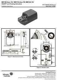


![[PDF] •Outdoor installation 4-5 - Johnson Controls](https://img.yumpu.com/10374038/1/184x260/pdf-ooutdoor-installation-4-5-johnson-controls.jpg?quality=85)

![[PDF] The European Products Catalogue 2012 - Johnson Controls](https://img.yumpu.com/3624903/1/184x260/pdf-the-european-products-catalogue-2012-johnson-controls.jpg?quality=85)