

Form 155.16-N3 (899), IsoFlow Absorption Chillers with Buffalo ...
Form 155.16-N3 (899), IsoFlow Absorption Chillers with Buffalo ...
Form 155.16-N3 (899), IsoFlow Absorption Chillers with Buffalo ...

Create successful ePaper yourself
Turn your PDF publications into a flip-book with our unique Google optimized e-Paper software.
Automatic Shut-Off Valve – (failsafe) This valve must<br />
shut off 100% of the hot water supply flow and be bubble<br />
tight during a cycling/safety shutdown or a power failure.<br />
The YORK supplied hot water control valve will remain<br />
in whatever position it happened to be in at the<br />
time of a power failure. Therefore, a valve that will completely<br />
shut-off hot water flow to the unit during such a<br />
failure is required to keep the unit from crystallization.<br />
Hot Water Control Valve (YORK supplied) – The<br />
hot water control valve is supplied by YORK and can<br />
be found in a separate box among the unit’s shipped<br />
loose parts. This valve must be connected to the appropriate<br />
wiring harness and will be used in a diverting service<br />
to control the temperature of hot water entering<br />
the unit. See Fig. 17 or 18 for a schematic on how to<br />
install the hot water control valve in a diverting service<br />
according to the valve’s manufacturer.<br />
If hot water supply is not shut off on unit shutdown,<br />
water will flow through the bypass. Special precautions<br />
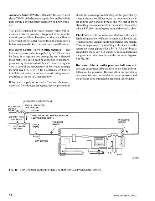
FIG. 19 – TYPICAL HOT WATER PIPING SYSTEM (SINGLE PASS GENERATOR)<br />
32<br />
should be taken to prevent heating of the generator by<br />
thermal circulation. Either locate the three-way hot water<br />
control valve and its bypass line two feet or more<br />
above the generator connection, or install a check valve<br />
<strong>with</strong> a 3/4" (19.1 mm) bypass around the check valve.<br />
Check Valve – On hot water unit shutdown, the water<br />
left in the generator will start to contract as it cools off.<br />
This may form a vacuum inside the generator tube bundle.<br />
This can be prevented by installing a check valve in the<br />
return hot water piping <strong>with</strong> a 3/4" (19.1 mm) bypass<br />
around the check valve. It should be installed between<br />
the generator outlet nozzle and the hot water bypass.<br />
See Fig. 19.<br />
Hot water inlet & outlet pressure indicator – A<br />
pressure gauge should be installed on the inlet and outlet<br />
lines of the generator. This will allow the operator to<br />
determine the inlet and outlet hot water pressure and<br />
the pressure drop through the generator tube bundle.<br />
LD00690B<br />
YORK INTERNATIONAL


![[PDF] •Outdoor installation 4-5 - Johnson Controls](https://img.yumpu.com/10374038/1/184x260/pdf-ooutdoor-installation-4-5-johnson-controls.jpg?quality=85)

![[PDF] The European Products Catalogue 2012 - Johnson Controls](https://img.yumpu.com/3624903/1/184x260/pdf-the-european-products-catalogue-2012-johnson-controls.jpg?quality=85)