

Form 155.16-N3 (899), IsoFlow Absorption Chillers with Buffalo ...
Form 155.16-N3 (899), IsoFlow Absorption Chillers with Buffalo ...
Form 155.16-N3 (899), IsoFlow Absorption Chillers with Buffalo ...

You also want an ePaper? Increase the reach of your titles
YUMPU automatically turns print PDFs into web optimized ePapers that Google loves.
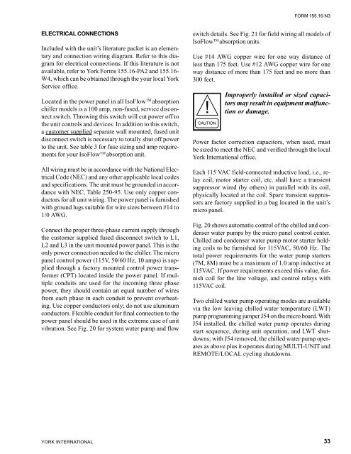
ELECTRICAL CONNECTIONS<br />
Included <strong>with</strong> the unit’s literature packet is an elementary<br />
and connection wiring diagram. Refer to this diagram<br />
for electrical connections. If this literature is not<br />
available, refer to York <strong>Form</strong>s <strong>155.16</strong>-PA2 and <strong>155.16</strong>-<br />
W4, which can be obtained through the your local York<br />
Service office.<br />
Located in the power panel in all <strong>IsoFlow</strong> TM absorption<br />
chiller models is a 100 amp, non-fused, service disconnect<br />
switch. Throwing this switch will cut power off to<br />
the unit controls and devices. In addition to this switch,<br />
a customer supplied separate wall mounted, fused unit<br />
disconnect switch is necessary to totally shut off power<br />
to the unit. See table 3 for fuse sizing and amp requirements<br />
for your <strong>IsoFlow</strong> TM absorption unit.<br />
All wiring must be in accordance <strong>with</strong> the National Electrical<br />
Code (NEC) and any other applicable local codes<br />
and specifications. The unit must be grounded in accordance<br />
<strong>with</strong> NEC, Table 250-95. Use only copper conductors<br />
for all unit wiring. The power panel is furnished<br />
<strong>with</strong> ground lugs suitable for wire sizes between #14 to<br />
1/0 AWG.<br />
Connect the proper three-phase current supply through<br />
the customer supplied fused disconnect switch to L1,<br />
L2 and L3 in the unit mounted power panel. This is the<br />
only power connection needed to the chiller. The micro<br />
panel control power (115V, 50/60 Hz, 10 amps) is supplied<br />
through a factory mounted control power transformer<br />
(CPT) located inside the power panel. If multiple<br />
conduits are used for the incoming three phase<br />
power, they should contain an equal number of wires<br />
from each phase in each conduit to prevent overheating.<br />
Use copper conductors only; do not use aluminum<br />
conductors. Flexible conduit for final connection to the<br />
power panel should be used in the extreme case of unit<br />
vibration. See Fig. 20 for system water pump and flow<br />
YORK INTERNATIONAL<br />
FORM <strong>155.16</strong>-<strong>N3</strong><br />
switch details. See Fig. 21 for field wiring all models of<br />
<strong>IsoFlow</strong> TM absorption units.<br />
Use #14 AWG copper wire for one way distance of<br />
less than 175 feet. Use #12 AWG copper wire for one<br />
way distance of more than 175 feet and no more than<br />
300 feet.<br />
Improperly installed or sized capacitors<br />
may result in equipment malfunction<br />
or damage.<br />
Power factor correction capacitors, when used, must<br />
be sized to meet the NEC and verified through the local<br />
York International office.<br />
Each 115 VAC field-connected inductive load, i.e., relay<br />
coil, motor starter coil, etc. shall have a transient<br />
suppressor wired (by others) in parallel <strong>with</strong> its coil,<br />
physically located at the coil. Spare transient suppressors<br />
are factory supplied in a bag located in the unit’s<br />
micro panel.<br />
Fig. 20 shows automatic control of the chilled and condenser<br />
water pumps by the micro panel control center.<br />
Chilled and condenser water pump motor starter holding<br />
coils to be furnished for 115VAC, 50/60 Hz. The<br />
total power requirements for the water pump starters<br />
(7M, 8M) must be a maximum of 1.0 amp inductive at<br />
115VAC. If power requirements exceed this value, furnish<br />
coil for the line voltage, and control relays <strong>with</strong><br />
115VAC coil.<br />
Two chilled water pump operating modes are available<br />
via the low leaving chilled water temperature (LWT)<br />
pump programming jumper J54 on the micro board. With<br />
J54 installed, the chilled water pump operates during<br />
start sequence, during unit operation, and LWT shutdowns;<br />
<strong>with</strong> J54 removed, the chilled water pump operates<br />
as above plus it operates during MULTI-UNIT and<br />
REMOTE/LOCAL cycling shutdowns.<br />
33


![[PDF] •Outdoor installation 4-5 - Johnson Controls](https://img.yumpu.com/10374038/1/184x260/pdf-ooutdoor-installation-4-5-johnson-controls.jpg?quality=85)

![[PDF] The European Products Catalogue 2012 - Johnson Controls](https://img.yumpu.com/3624903/1/184x260/pdf-the-european-products-catalogue-2012-johnson-controls.jpg?quality=85)