

Form 155.16-N3 (899), IsoFlow Absorption Chillers with Buffalo ...
Form 155.16-N3 (899), IsoFlow Absorption Chillers with Buffalo ...
Form 155.16-N3 (899), IsoFlow Absorption Chillers with Buffalo ...

Create successful ePaper yourself
Turn your PDF publications into a flip-book with our unique Google optimized e-Paper software.
YORK INTERNATIONAL<br />
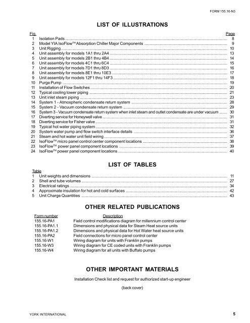
LIST OF ILLUSTRATIONS<br />
FORM <strong>155.16</strong>-<strong>N3</strong><br />
Fig. Page<br />
1 Isolation Pads .............................................................................................................................................. 8<br />
2 Model YIA <strong>IsoFlow</strong> TM <strong>Absorption</strong> Chiller Major Components ......................................................................... 9<br />
3 Unit Rigging ................................................................................................................................................. 10<br />
4 Unit assembly for models 1A1 thru 2A4 ....................................................................................................... 13<br />
5 Unit assembly for models 2B1 thru 4B4 ....................................................................................................... 14<br />
6 Unit assembly for models 4C1 thru 6C4 ....................................................................................................... 15<br />
7 Unit assembly for models 7D1 thru 8D3 ....................................................................................................... 16<br />
8 Unit assembly for models 8E1 thru 10E3 ..................................................................................................... 17<br />
9 Unit assembly for models 12F1 thru 14F3.................................................................................................... 18<br />
10 Purge Pump ................................................................................................................................................ 19<br />
11 Installation of Flow Switches ........................................................................................................................ 20<br />
12 Typical cooling tower piping ......................................................................................................................... 21<br />
13 Unit inlet steam piping ................................................................................................................................. 23<br />
14 System 1 - Atmospheric condensate return system .................................................................................... 28<br />
15 System 2 - Vacuum condensate return system ........................................................................................... 29<br />
16 System 3 - Vacuum condensate return system when inlet steam and outlet condensate are under vacuum ....... 30<br />
17 Diverting service for Honeywell valve ............................................................................................................. 31<br />
18 Diverting service for Fisher valve ................................................................................................................... 31<br />
19 Typical hot water piping system ................................................................................................................... 32<br />
20 System water pump and flow switch interface details .................................................................................. 36<br />
21 Steam and hot water unit field wiring ............................................................................................................ 37<br />
22 <strong>IsoFlow</strong> TM micro panel control center component locations .......................................................................... 38<br />
23 <strong>IsoFlow</strong> TM power panel component locations ............................................................................................... 39<br />
24 <strong>IsoFlow</strong> TM power panel component locations ................................................................................................ 40<br />
LIST OF TABLES<br />
Table<br />
1 Unit weights and dimensions ....................................................................................................................... 11<br />
2 Shell and tube volumes ................................................................................................................................ 27<br />
3 Electrical ratings .......................................................................................................................................... 34<br />
4 Approximate insulation for hot and cold surfaces ......................................................................................... 42<br />
5 Unit Charge Quantities ................................................................................................................................ 43<br />
OTHER RELATED PUBLICATIONS<br />
<strong>Form</strong> number Description<br />
<strong>155.16</strong>-PA1 Field control modifications diagram for millennium control center<br />
<strong>155.16</strong>-PA1.1 Dimensions and physical data for Steam Heat source units<br />
<strong>155.16</strong>-PA1.2 Dimensions and physical data for Hot Water heat source units<br />
<strong>155.16</strong>-PA2 Field connections for micro panel control center<br />
<strong>155.16</strong>-W1 Wiring diagram for units <strong>with</strong> Franklin pumps<br />
<strong>155.16</strong>-W3 Wiring diagram for CE coded units <strong>with</strong> Franklin pumps<br />
<strong>155.16</strong>-W4 Wiring diagram for all units <strong>with</strong> <strong>Buffalo</strong> pumps<br />
OTHER IMPORTANT MATERIALS<br />
Installation Check list and request for authorized start-up engineer<br />
(back cover)<br />
5


![[PDF] •Outdoor installation 4-5 - Johnson Controls](https://img.yumpu.com/10374038/1/184x260/pdf-ooutdoor-installation-4-5-johnson-controls.jpg?quality=85)

![[PDF] The European Products Catalogue 2012 - Johnson Controls](https://img.yumpu.com/3624903/1/184x260/pdf-the-european-products-catalogue-2012-johnson-controls.jpg?quality=85)