

Form 155.16-N3 (899), IsoFlow Absorption Chillers with Buffalo ...
Form 155.16-N3 (899), IsoFlow Absorption Chillers with Buffalo ...
Form 155.16-N3 (899), IsoFlow Absorption Chillers with Buffalo ...

Create successful ePaper yourself
Turn your PDF publications into a flip-book with our unique Google optimized e-Paper software.
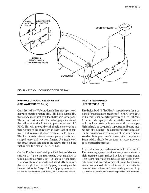
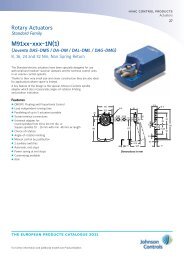
FIG. 12 – TYPICAL COOLING TOWER PIPING<br />
RUPTURE DISK AND RELIEF PIPING<br />
(HOT WATER UNITS ONLY)<br />
Only the <strong>IsoFlow</strong> TM absorption chillers that operate on<br />
hot water require a rupture disk. This disk is supplied by<br />
the factory and is sent <strong>with</strong> the chiller ship loose parts.<br />
The rupture disk is made of a carbon graphite material<br />
that will rupture should the unit pressure exceed 15.0<br />
PSIG. This will protect the unit should there ever be a<br />
tube rupture or the extremely unlikely case of abnormally<br />
high refrigerant vapor pressure inside the unit.<br />
The disk mounts between two neoprene gaskets (also<br />
shipped loose) and two steel flanges. Use graphite on<br />
the screw threads and torque the screws that hold the<br />
rupture disk to a max of 15-1/2 ft.-Lbs.<br />
On the 4" schedule 40 stub provided, butt weld other<br />
sections of 4" pipe and route piping over and down to<br />
terminate approximately 10"- 12" above a floor drain.<br />
Use adequate pipe supports and stand offs to ensure<br />
that no weight from the relief piping is bearing on the<br />
rupture disk or its flange. All relief piping must be installed<br />
in accordance <strong>with</strong> local, state or federal codes.<br />
YORK INTERNATIONAL<br />
INLET STEAM PIPING<br />
(REFER TO FIG. 13)<br />
FORM <strong>155.16</strong>-<strong>N3</strong><br />
LD00941<br />
The design level “B” <strong>IsoFlow</strong> TM absorption chiller is designed<br />
for a maximum pressure of 15 PSIG (103 kPa),<br />
<strong>with</strong> a maximum steam temperature of 337°F (169°C).<br />
All steam field piping should be installed in accordance<br />
<strong>with</strong> any local, state or federal codes that may apply.<br />
Piping should be adequately supported and braced independent<br />
of the chiller. The support system must account<br />
for the expansion and contraction of the steam piping,<br />
avoiding the imposition of strain on chiller components.<br />
Steam piping should be designed in accordance <strong>with</strong><br />
good engineering practice.<br />
A typical steam piping diagram is laid out in Fig. 13.<br />
The steam supply may be either low pressure steam or<br />
high pressure steam reduced to low pressure steam.<br />
Both steam supply and condensate pipes must be properly<br />
sized and pitched to prevent liquid hammering.<br />
Steam mains should be sized in accordance <strong>with</strong> the<br />
required steam flow and acceptable pressure drop.<br />
Wherever possible, the steam supply line to the absorp-<br />
21


![[PDF] •Outdoor installation 4-5 - Johnson Controls](https://img.yumpu.com/10374038/1/184x260/pdf-ooutdoor-installation-4-5-johnson-controls.jpg?quality=85)

![[PDF] The European Products Catalogue 2012 - Johnson Controls](https://img.yumpu.com/3624903/1/184x260/pdf-the-european-products-catalogue-2012-johnson-controls.jpg?quality=85)