

Form 155.16-N3 (899), IsoFlow Absorption Chillers with Buffalo ...
Form 155.16-N3 (899), IsoFlow Absorption Chillers with Buffalo ...
Form 155.16-N3 (899), IsoFlow Absorption Chillers with Buffalo ...

Create successful ePaper yourself
Turn your PDF publications into a flip-book with our unique Google optimized e-Paper software.
INSTALLING THE ABSOLUTE PRESSURE GAUGE<br />
The absolute pressure gauge is shipped separately for<br />
field installation. Mount the gauge on the gauge bracket<br />
which is located on the lower shell of the unit adjacent<br />
to the purge piping. Use #10-24 UNC x 1 inch long flat<br />
head machine screws and #10-24 UNC hex nuts. Make<br />
sure the gauge is absolutely vertical by placing a level<br />
on the side edge of the gauge before tightening the<br />
mounting screws. The gauge can be connected to the<br />
manometer isolation hand valve via tubing. When doing<br />
so, make sure the hand valve is in the closed position.<br />
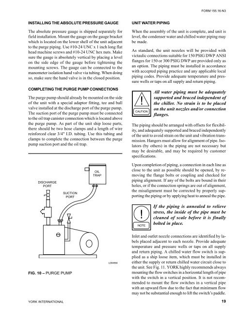
COMPLETING THE PURGE PUMP CONNECTIONS<br />
The purge pump should already be mounted on the side<br />
of the unit <strong>with</strong> a special adaptor fitting, tee and ball<br />
valve installed at the discharge port of the purge pump.<br />
The suction port of the purge pump must be connected<br />
to the oil trap canister connection which is located above<br />
the purge pump. As part of the unit ship loose parts,<br />
there should be two hose clamps and a length of wire<br />
reinforced clear 3/4" I.D. tubing. Use this tubing and<br />
clamps to complete the connection between the purge<br />
pump suction port and the oil trap.<br />
DISCHARGE<br />
PORT<br />
YORK INTERNATIONAL<br />
SUCTION<br />
PORT<br />
FIG. 10 – PURGE PUMP<br />
OIL<br />
TRAP<br />
LD04564<br />
UNIT WATER PIPING<br />
FORM <strong>155.16</strong>-<strong>N3</strong><br />
When the assembly of the unit is complete, and unit is<br />
level, the condenser water and chilled water piping may<br />
be made.<br />
As standard, the unit nozzles will be provided <strong>with</strong><br />
victaulic connections suitable for 150 PSIG DWP ANSI<br />
flanges for 150 or 300 PSIG DWP are provided only as<br />
an option. The piping must be installed in accordance<br />
<strong>with</strong> accepted piping practice and any applicable local<br />
piping codes. Provide adequate temperature and pressure<br />
wells or taps on all supply and return piping.<br />
All water piping must be adequately<br />
supported and braced independent of<br />
the chiller. No strain is to be placed<br />
on the unit nozzles and/or connection<br />
flanges.<br />
The piping should be arranged <strong>with</strong> offsets for flexibility,<br />
and adequately supported and braced independently<br />
of the unit to avoid strain on the unit and vibration transmission.<br />
Hangers must allow for alignment of pipe. Isolators<br />
(by others) in the piping are not necessary but<br />
may be desirable, and may be required by customer<br />
specifications.<br />
Upon completion of piping, a connection in each line as<br />
close to the unit as possible should be opened, by removing<br />
the flange bolts or coupling and checked for<br />
piping alignment. If any of the bolts are bound in their<br />
holes, or if the connection springs are out of alignment,<br />
the misalignment must be corrected by properly supporting<br />
the piping or by applying heat to anneal the pipe.<br />
If the piping is annealed to relieve<br />
stress, the inside of the pipe must be<br />
cleaned of scale before it is finally<br />
bolted in place.<br />
Inlet and outlet nozzle connections are identified by labels<br />
placed adjacent to each nozzle. Provide adequate<br />
temperature and pressure wells or taps on all supply<br />
and return piping. A chilled water flow switch is supplied<br />
as a ship loose item, which must be installed in<br />
either the supply or return chilled water circuit close to<br />
the unit. See Fig. 11. YORK highly recommends always<br />
mounting the flow switches in a horizontal length of pipe<br />
<strong>with</strong> the switch in a vertical position. It is not recommended<br />
to mount the flow switches in a vertical pipe<br />
<strong>with</strong> an upward flow due to the fact that minimum flow<br />
may not be substantial enough to lift the switch’s paddle.<br />
19


![[PDF] •Outdoor installation 4-5 - Johnson Controls](https://img.yumpu.com/10374038/1/184x260/pdf-ooutdoor-installation-4-5-johnson-controls.jpg?quality=85)

![[PDF] The European Products Catalogue 2012 - Johnson Controls](https://img.yumpu.com/3624903/1/184x260/pdf-the-european-products-catalogue-2012-johnson-controls.jpg?quality=85)