

Form 155.16-N3 (899), IsoFlow Absorption Chillers with Buffalo ...
Form 155.16-N3 (899), IsoFlow Absorption Chillers with Buffalo ...
Form 155.16-N3 (899), IsoFlow Absorption Chillers with Buffalo ...

You also want an ePaper? Increase the reach of your titles
YUMPU automatically turns print PDFs into web optimized ePapers that Google loves.
20<br />
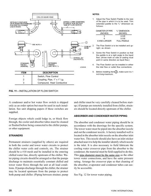
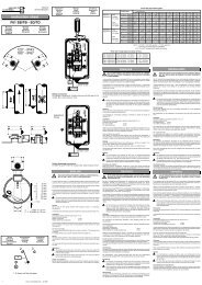
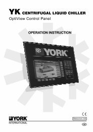
ITEM DESCRIPTION<br />
1 Switch, Flow Control<br />
2 Coupling, Pipe, 1” x 1” Lg.<br />
3 Compound, Heat Conductive<br />
FIG. 11 – INSTALLATION OF FLOW SWITCH<br />
A condenser and/or hot water flow switch is shipped<br />
only as an order option but must be used in each installation.<br />
See unit shipping papers if these switches are<br />
supplied.<br />
Foreign objects which could lodge in, or block flow<br />
through, the cooler and absorber tubes must be cleaned<br />
or flushed before being connected to the chiller pumps,<br />
or other equipment.<br />
STRAINERS<br />
Permanent strainers (supplied by others) are required<br />
in both the cooler and tower water circuits to protect<br />
the chiller water coils and controls, etc. The strainer<br />
should be a #10 mesh and be installed in the entering<br />
chilled water line, directly upstream of the chiller. Water<br />
piping circuits should be arranged so that the pumps<br />
discharge to maintain essentially constant chilled and<br />
tower water flows through the unit at all load conditions.<br />
If pumps discharge through the chiller, the strainer<br />
may be located upstream from the pumps to protect<br />
both pump and chiller. (Piping between strainer, pump<br />
LD00939<br />
NOTES:<br />
1. Adjust the Flow Switch Paddle to the size<br />
of the pipe in which it is to be used. Trim<br />
extended paddle to the “L” dimension as<br />
follows:<br />
DIAMETER OF PIPE “L” DIMENSION<br />
(INCHES) (INCHES)<br />
5 4-5/8<br />
6 5-5/8<br />
8 AND LARGER FULL PADDLE<br />
2. The Flow Switch is to be installed and upright,<br />
as shown.<br />
3. Screw the Flow Switch in position so that<br />
the paddle is at a right angle to the liquid<br />
flow. (Arrow mark on side of casting must<br />
point in same direction as liquid flow.)<br />
4. The Flow Switch can be installed in either<br />
the inlet flow or outlet flow connections.<br />
5. Before installing Item 2 , make sure it is 1<br />
inch long maximum.<br />
and chiller must be very carefully cleaned before startup.)<br />
If pumps are remotely installed from chiller, strainers<br />
should be located directly upstream of the chiller.<br />
ABSORBER AND CONDENSER WATER PIPING<br />
The absorber and condenser water piping should be in<br />
accordance <strong>with</strong> the drawings for the specific system.<br />
The tower water must be piped into the absorber nozzle<br />
and out the condenser nozzle. A factory installed well is<br />
located in the absorber inlet nozzle on the absorber inlet<br />
water box. This nozzle should also have an inlet sticker<br />
attached near it to help the installer identify which nozzle<br />
is the inlet. It is also necessary to field fabricate the<br />
cooling water crossover pipe from the absorber to the<br />
condenser, the material must be field supplied to do this.<br />
This pipe diameter must be the same size as the other<br />
tower water connections, and have the same pressure<br />
rating. Arrange the crossover pipe so that cleaning of<br />
the absorber, evaporator and condenser tubes can easily<br />
be accessible.<br />
See Fig. 12 for tower water piping.<br />
YORK INTERNATIONAL


![[PDF] •Outdoor installation 4-5 - Johnson Controls](https://img.yumpu.com/10374038/1/184x260/pdf-ooutdoor-installation-4-5-johnson-controls.jpg?quality=85)

![[PDF] The European Products Catalogue 2012 - Johnson Controls](https://img.yumpu.com/3624903/1/184x260/pdf-the-european-products-catalogue-2012-johnson-controls.jpg?quality=85)