

Form 155.16-N3 (899), IsoFlow Absorption Chillers with Buffalo ...
Form 155.16-N3 (899), IsoFlow Absorption Chillers with Buffalo ...
Form 155.16-N3 (899), IsoFlow Absorption Chillers with Buffalo ...

You also want an ePaper? Increase the reach of your titles
YUMPU automatically turns print PDFs into web optimized ePapers that Google loves.
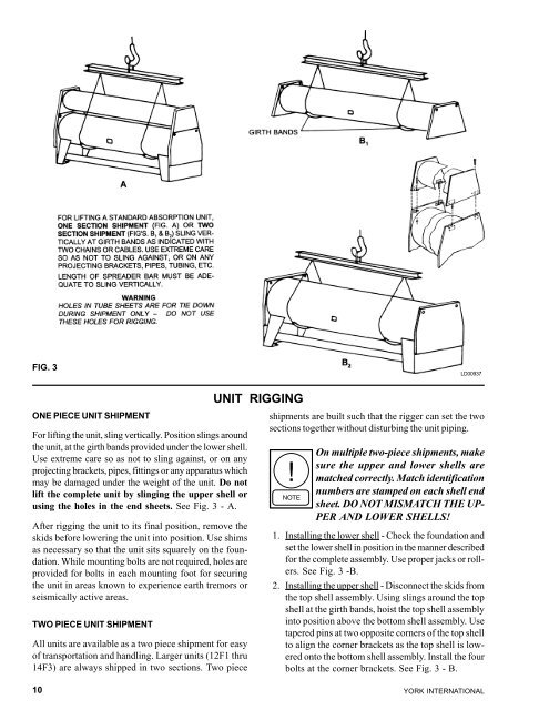
FIG. 3<br />
ONE PIECE UNIT SHIPMENT<br />
For lifting the unit, sling vertically. Position slings around<br />
the unit, at the girth bands provided under the lower shell.<br />
Use extreme care so as not to sling against, or on any<br />
projecting brackets, pipes, fittings or any apparatus which<br />
may be damaged under the weight of the unit. Do not<br />
lift the complete unit by slinging the upper shell or<br />
using the holes in the end sheets. See Fig. 3 - A.<br />
After rigging the unit to its final position, remove the<br />
skids before lowering the unit into position. Use shims<br />
as necessary so that the unit sits squarely on the foundation.<br />
While mounting bolts are not required, holes are<br />
provided for bolts in each mounting foot for securing<br />
the unit in areas known to experience earth tremors or<br />
seismically active areas.<br />
TWO PIECE UNIT SHIPMENT<br />
All units are available as a two piece shipment for easy<br />
of transportation and handling. Larger units (12F1 thru<br />
14F3) are always shipped in two sections. Two piece<br />
10<br />
UNIT RIGGING<br />
LD00937<br />
shipments are built such that the rigger can set the two<br />
sections together <strong>with</strong>out disturbing the unit piping.<br />
On multiple two-piece shipments, make<br />
sure the upper and lower shells are<br />
matched correctly. Match identification<br />
numbers are stamped on each shell end<br />
sheet. DO NOT MISMATCH THE UP-<br />
PER AND LOWER SHELLS!<br />
1. Installing the lower shell - Check the foundation and<br />
set the lower shell in position in the manner described<br />
for the complete assembly. Use proper jacks or rollers.<br />
See Fig. 3 -B.<br />
2. Installing the upper shell - Disconnect the skids from<br />
the top shell assembly. Using slings around the top<br />
shell at the girth bands, hoist the top shell assembly<br />
into position above the bottom shell assembly. Use<br />
tapered pins at two opposite corners of the top shell<br />
to align the corner brackets as the top shell is lowered<br />
onto the bottom shell assembly. Install the four<br />
bolts at the corner brackets. See Fig. 3 - B.<br />
YORK INTERNATIONAL


![[PDF] •Outdoor installation 4-5 - Johnson Controls](https://img.yumpu.com/10374038/1/184x260/pdf-ooutdoor-installation-4-5-johnson-controls.jpg?quality=85)

![[PDF] The European Products Catalogue 2012 - Johnson Controls](https://img.yumpu.com/3624903/1/184x260/pdf-the-european-products-catalogue-2012-johnson-controls.jpg?quality=85)