

Form 155.16-N3 (899), IsoFlow Absorption Chillers with Buffalo ...
Form 155.16-N3 (899), IsoFlow Absorption Chillers with Buffalo ...
Form 155.16-N3 (899), IsoFlow Absorption Chillers with Buffalo ...

Create successful ePaper yourself
Turn your PDF publications into a flip-book with our unique Google optimized e-Paper software.
Vacuum Breaker (if desired) – A vacuum breaker<br />
will often not be necessary, but one can prevent condensate<br />
build up in the generator bundle of the chiller at<br />
part loads.<br />
If an atmospheric return system is used the generator<br />
will not operate in the vacuum region, but will operate<br />
at atmospheric pressure even at low load conditions.<br />
Throttling of the steam valve at low load results in steam<br />
condensate to back-up into the generator tubes. As the<br />
load increases, the steam valve will open further to raise<br />
the steam pressure and push the backed-up condensate<br />
out of the generator. The accumulation of condensate<br />
in the generator at reduced loads and subsequent drainage<br />
will have no adverse effect on absorption unit efficiency.<br />
However, due to the cyclical drainage of condensate<br />
from the unit, the main system condensate receiver<br />
must be sized <strong>with</strong> sufficient additional capacity<br />
to accommodate this fluctuation of condensate quantities.<br />
The capacity of the main system condensate receiver<br />
is assumed to be equal to the absorption unit generator<br />
tube volume as a maximum - See Table 2 for<br />
<strong>IsoFlow</strong> TM Unit Shell and Tube Volumes.<br />
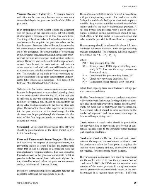
To help avoid fluctuation in condensate return or water<br />
hammer in the generator, a vacuum breaker swing check<br />
valve can be added as shown in Fig. 17. A 3/8 inch size<br />
is sufficient to prevent condensate build-up and water<br />
hammer. For safety, a pipe should be installed from the<br />
check valve to a location close to the floor or other safe<br />
place. The use of the check valve to permit air entrance<br />
into the generator tubes has the disadvantage that this<br />
air must later be purged through the thermostatic element<br />
of the float trap and tends to entrain air in the<br />
condensate return.<br />
Strainer(s) – A fine mesh strainer <strong>with</strong> a blow-off valve<br />
should be provided ahead of the steam trap(s) to protect<br />
it from damage.<br />
Float and Thermostatic Steam Trap(s) – This float<br />
and trap serve the purpose of passing condensate, but<br />
preventing the loss of steam. The float and thermostatic<br />
steam trap should be applied in accordance <strong>with</strong> the<br />
manufacturer’s recommendations. The trap should be<br />
located as close to the generator condensate outlet as<br />
possible in the horizontal plane. In the vertical plane, the<br />
trap should be located below the generator condensate<br />
outlet, a minimum of 12 inches (0.3m).<br />
Preferably, the maximum possible elevation between the<br />
generator outlet and the trap should be used.<br />
YORK INTERNATIONAL<br />
FORM <strong>155.16</strong>-<strong>N3</strong><br />
The condensate outlet line should be sized in accordance<br />
<strong>with</strong> good engineering practice for condensate at the<br />
flash point and should be kept as short and simple as<br />
possible. Stop valves should be provided ahead of the<br />
strainer and after the trap for maintenance purposes. A<br />
full size bypass line provided <strong>with</strong> a globe valve for<br />
manual operation during maintenance should be supplied.<br />
Also, a full trap outlet line size connection and<br />
valve should be provided for blow-off and test purposes.<br />
The steam trap should be selected for about 1.5 times<br />
the design full steam flow rate, at the design operating<br />
pressure differential. The operating full load pressure<br />
differential: PD = SP - P 1 - P 2 - P 3<br />
Where:<br />
PD = Trap pressure drop, PSI<br />
SP = Steam pressure, PSIG, at generator flange normally<br />
3 PSI less than the design pressure to<br />
the control valve.<br />
P 1 = Condensate line pressure drop losses, PSI<br />
P 2 = Check valve pressure drop loss, PSI<br />
P 3 = Condensate cooler pressure drop loss, PSI<br />
Select float capacity from manufacturer’s ratings per<br />
above recommendations.<br />
The line from the steam trap to the condensate receiver<br />
will contain some flash vapor flowing <strong>with</strong> the condensate.<br />
This line should always be a short as possible, preferably<br />
not more than 30 feet (9m) in equivalent length.<br />
As a general rule, it should be sized according to the<br />
number of traps used and one or more sizes larger in<br />
the case of longer piping runs.<br />
Check Valve – A check valve should be provided in<br />
the trap outlet line to prevent any possible air or condensate<br />
leakage back to the generator under reduced<br />
load operating conditions.<br />
Condensate Cooler – The use of a condensate cooler<br />
between the trap and the condensate receiver to cool<br />
the condensate below its flash point is required for<br />
vacuum return systems and may be desirable, though<br />
not required, for atmospheric return systems.<br />
The variations in condensate flow must be recognized<br />
and the cooler selected to cool the maximum flow of<br />
condensate 5 - 10°F (3 - 6°C) below the saturation temperature<br />
of the lowest pressure in the system (atmospheric<br />
pressure for an atmospheric return or the lowest<br />
pressure in a vacuum return system). Sufficient<br />
25

![[PDF] •Outdoor installation 4-5 - Johnson Controls](https://img.yumpu.com/10374038/1/184x260/pdf-ooutdoor-installation-4-5-johnson-controls.jpg?quality=85)
![[PDF] The European Products Catalogue 2012 - Johnson Controls](https://img.yumpu.com/3624903/1/184x260/pdf-the-european-products-catalogue-2012-johnson-controls.jpg?quality=85)