

YK CENTRIFUGAL LIQUID CHILLER OptiView ... - Johnson Controls
YK CENTRIFUGAL LIQUID CHILLER OptiView ... - Johnson Controls
YK CENTRIFUGAL LIQUID CHILLER OptiView ... - Johnson Controls

Create successful ePaper yourself
Turn your PDF publications into a flip-book with our unique Google optimized e-Paper software.
<strong>YK</strong> <strong>CENTRIFUGAL</strong> <strong>LIQUID</strong> <strong>CHILLER</strong><br />
<strong>OptiView</strong> Control Panel<br />
OPERATION INSTRUCTION<br />
Effective from 11/00<br />
GB
i 160-54-OI-GB0<br />
1 HOME SCREEN 4<br />
2 SYSTEM SCREEN 5<br />
3 EVAPORATOR SCREEN 6<br />
4 CONDENSER SCREEN 8<br />
5 COMPRESSOR SCREEN 9<br />
6 OIL SUMP SCREEN 10<br />
7 MOTOR SCREENS 11<br />
7.1 EM STARTER SCREEN 11<br />
Contents<br />
7.2SOLID STATE STARTER SCREEN 12<br />
7.3 VSD SCREEN 13<br />
8 SETPOINTS SCREEN 15<br />
8.1 SETUP SCREEN 17<br />
9 HISTORY SCREEN 22<br />
9.1 TRENDS SCREEN 23<br />
9.2CUSTOM SCREEN 26<br />
10 DISPLAY MESSAGES 27<br />
10.1 SYSTEM STATUS Messages 27<br />
10.2SYSTEM DETAILS Messages 28<br />
10.3 Cycling Shutdown Messages 31<br />
10.4 Safety Shutdown Messages 39
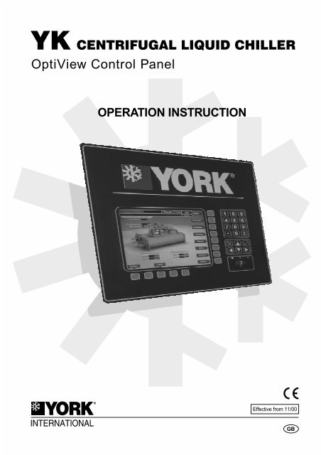
<strong>OptiView</strong> Control Panel<br />
Display<br />
Soft keys for Control and Navigation<br />
The YORK <strong>OptiView</strong> Control Panel (Graphic Control<br />
Centre) is a microprocessor based control system for<br />
<strong>YK</strong> centrifugal chillers. It controls the leaving chilled<br />
liquid temperature via pre-rotation vane (PRV) controls<br />
and has the ability to limit motor current via control of the<br />
PRV. It is compatible with electro-mechanical starter,<br />
optional YORK Solid State Starter (SSS) and optional<br />
Variable Speed Drive (VSD) applications.<br />
The panel has a full screen LCD graphic display with a<br />
keypad interface. The graphic display allows the<br />
presentation of several operating parameters at once. In<br />
addition, the operator may view a graphical<br />
representation of the historical operation of the unit as<br />
well as the present operation.<br />
For ease of use the locations of displayed parameters<br />
are clearly and intuitively marked and instructions for<br />
specific operations are provided on many of the<br />
screens. Information can be displayed in both metric (SI<br />
- temperatures in °C and pressures in kPa) or English<br />
(Imperial - temperatures in °F and pressures in PSIG)<br />
units in a number of languages.<br />
The control panel also displays the unit operation using<br />
status and warning messages and records the cause of<br />
any shutdowns (Safety, Cycling or Normal). This<br />
information is stored in battery backed for viewing.<br />
1<br />
4<br />
7<br />
2<br />
5<br />
8<br />
0<br />
3<br />
6<br />
9<br />
+<br />
-<br />
160-54-OI-GB0 1<br />
Numeric<br />
Keypad<br />
Cursor Keys/<br />
Cancel and<br />
Enter<br />
Master<br />
Switch<br />
Information on the display falls into three distinct groups:<br />
Display Only, Programmable, and Navigation. The<br />
Programmable values and Navigation commands are<br />
subject to access level control.<br />
Display Only information is read-only parameters<br />
about unit operation. This information may be<br />
represented by a numerical value, a text string, or an<br />
LED image. For numerical values, if the monitored<br />
parameter is above the normal operating range, the high<br />
limit value will be displayed along with the '>' symbol; if it<br />
is below the normal operating range, the low limit value<br />
will be displayed along with the '
Access Level Three access levels are available:<br />
View<br />
This is the default access level (available automatically<br />
when power is applied to the unit) allowing navigation of<br />
the screens and access to display only information.<br />
Operator<br />
This access level is entered using the 'LOGIN' button on<br />
the 'HOME SCREEN'. A User ID and Password have to<br />
be entered using the numeric keypad. 'OPERATOR'<br />
access automatically reverts to the 'VIEW' after 10<br />
minutes without a key-press. The 'OPERATOR' access<br />
level allows navigation of the screens, access to display<br />
only information and programming of a number of<br />
system settings.<br />
Service<br />
2 160-54-OI-GB0<br />
'OPERATOR' access level can also be<br />
entered directly from the 'SETPOINTS<br />
SCREEN' without returning to the 'HOME<br />
SCREEN'.<br />
'SERVICE' access level is for qualified service<br />
personnel only.<br />
The 'soft' keys surrounding the display are redefined<br />
based on the currently displayed screen. The buttons on<br />
the right side and base of the panel are used for<br />
navigation and selection of parameters. The keypad is<br />
used for data entry with a standard numeric keypad<br />
provided for entry of system setpoints and limits.<br />
The Decimal key provides accurate entry of setpoint<br />
values.<br />
The +/- key allows entry of negative values and AM/PM<br />
selection during time entry.<br />
The ' ✓ ' (Check) key is provided as a universal 'Enter' or<br />
'Accept'' key to confirm changes made.<br />
The ' X ' key is provided as a universal 'Cancel' key to<br />
reject changes made.<br />
Cursor Arrow keys ( are provided to allow<br />
movement on screens which contain a large amount of<br />
entry data. In addition, these keys can be used to scroll<br />
through history and event logs.<br />
Setpoint Programming<br />
Setpoint values are used to control the unit and devices<br />
connected to the system. Setpoints can be numeric<br />
values (such as 7°C for the Leaving Chilled Liquid<br />
Temperature), or an Enable or Disable function. The<br />
following procedure applies when programming<br />
setpoints:<br />
Press the desired setpoint key and a dialogue box<br />
appears displaying the present value, the upper<br />
and lower limits of the programmable range, and<br />
the default value.<br />
When the dialogue box begins with the word<br />
'ENTER', the numeric keys should be used to enter<br />
the desired value. Leading zeroes are not<br />
necessary. If a decimal point is necessary, press<br />
the ' ' key.<br />
Pressing the key, sets the entry value to the default<br />
for that setpoint. Pressing the key, clears the present<br />
entry. The key is a backspace key and causes the<br />
entry point to move back one space.<br />
If the dialogue box begins with 'SELECT', use the<br />
and keys to select the desired value.<br />
If the previously defined setpoint is correct, press the ' X '<br />
(Cancel) key to dismiss the dialogue box.<br />
Press the ' ✓ ' (Enter) key.<br />
If the value is within range, it is accepted and the<br />
dialogue box disappears. The unit will begin to operate<br />
based on the new programmed value. If out of range, the<br />
value will not be accepted and the user is prompted to try<br />
again.
Master Switch<br />
The three-position rocker switch is the master control.<br />
When toggled right, it is in the 'STOP/RESET' position,<br />
the middle position is 'RUN' and when momentarily<br />
toggled left it is in the 'START' position.<br />
In the 'STOP/RESET' position the unit will not run under<br />
any condition, this enables maintenance and other<br />
tasks to be completed safely. In addition, the switch<br />
must be placed in this position following certain<br />
shutdowns before the unit is allowed to restart. This<br />
guarantees that manual intervention has taken place<br />
and the shutdown has been acknowledged.<br />
The 'START' position is used to locally start the unit.<br />
When set to this position with no fault conditions, the unit<br />
will enter the system pre-lube (start sequence).<br />
In the 'RUN' position the unit will operate normally and<br />
automatically restart following cycling shutdowns. The<br />
switch must be in this position to receive a valid remote<br />
start signal when operating from a remote control<br />
source.<br />
Remote Control<br />
The control panel expands the capabilities of remote<br />
control and communications. By providing a common<br />
networking protocol through the ISN, YORK units can<br />
be standalone or part of a group.<br />
This new protocol allows increased remote control of the<br />
unit, as well as 24-hour performance monitoring via a<br />
remote site. In addition, compatibility is maintained with<br />
the present network of ISN communications.<br />
The unit also maintains the standard digital remote<br />
capabilities as well. Both of these remote control<br />
capabilities allow for the standard Energy Management<br />
System (EMS) interface:<br />
Remote Start; Remote Stop and Remote Ready to<br />
Start contacts.<br />
Remote Leaving Chilled Liquid Temperature<br />
Setpoint and Remote Current Limit Setpoint<br />
adjustment (0-10VDC, 2-10VDC, 0-20mA or<br />
4-20mA) or Pulse Width Modulation.<br />
Cycling and Safety Shutdown Contacts<br />
160-54-OI-GB0 3<br />
There are certain displayed values, programmable<br />
setpoints and controls shown in this manual that<br />
are for Service Technician use only. These are<br />
only displayed when logged in at SERVICE access<br />
level or higher. The setpoints and parameters<br />
displayed on these screens are explained in detail<br />
in manual 160.54-M1.<br />
These parameters affect unit operation<br />
and should NEVER be modified by anyone<br />
other than a qualified Service Technician.
4 160-54-OI-GB0<br />
1 HOME SCREEN<br />
The 'HOME SCREEN' is displayed by default (at the<br />
'VIEW ACCESS LEVEL') when the unit is powered on.<br />
This screen shows the main operating values, enables<br />
system access and permits further navigation to the sub<br />
screens.<br />
The Login/Logout key is used to enter/exit the<br />
'OPERATOR' and 'SERVICE' 'ACCESS LEVEL' from<br />
the 'VIEW ACCESS LEVEL'<br />
The Print key should be used to obtain a hard-copy print<br />
of the current system status.<br />
The Warning Reset key is used at<br />
'OPERATOR/SERVICE ACCESS LEVEL' to<br />
acknowledge and reset 'WARNING' messages<br />
(displayed in yellow), refer to Section 10 for details of<br />
display messages and their meaning.<br />
The Message Clear key is used at 'SERVICE ACCESS<br />
LEVEL' to clear 'SAFETY' or 'CYCLING' shutdown<br />
messages (displayed in red and orange), refer to<br />
Section 10 for details of display messages and their<br />
meaning.<br />
System key (see Section 2)<br />
Evaporator key (see Section 3)<br />
Condenser key (see Section 4)<br />
Compressor key (see Section 5)<br />
Oil Sump key (see Section 6)<br />
Motor key (see Section 7)<br />
Setpoints key (see Section 8)<br />
History key (see Section 9)
2 SYSTEM SCREEN<br />
The 'SYSTEM SCREEN' displays pressures and<br />
temperatures for the evaporator, condenser,<br />
compressor and oil system. Electrical load and current<br />
limit are also shown.<br />
160-54-OI-GB0 5
3 EVAPORATOR SCREEN<br />
The 'EVAPORATOR SCREEN' displays a cutaway view<br />
of the unit evaporator showing current operating<br />
temperatures and pressures, status of the flow switch<br />
and liquid pump signal and the control setpoints.<br />
The local leaving chilled liquid temperature 'SETPOINT'<br />
and 'RANGE', and leaving chilled liquid temperature<br />
cycling offset 'SHUTDOWN' and 'RESTART' values are<br />
also programmed on this screen:<br />
Setpoint<br />
6 160-54-OI-GB0<br />
Defines the leaving chilled liquid temperature that is to<br />
be maintained by the unit. The 'SETPOINT' can be<br />
programmed between 3.3°C (38°F) and 21.1°C (70°F)<br />
for water cooling applications or -12.2°C (10°F) and<br />
21.1°C (70°F) for brine/glycol applications.<br />
When Smart Freeze has been enabled by a<br />
qualified Service Technician, the<br />
programmable 'SETPOINT' is 2.2°C (36°F) to<br />
21.1°C (70°F) for water cooling applications.<br />
Range<br />
The programmed 'SETPOINT' can be reset (offset)<br />
upwards by an analogue signal: (0-20 mA, 4-20 mA,<br />
0-10 Vdc or 2-10 Vdc) in the analogue remote mode, or<br />
PWM signal in digital remote mode. The offset<br />
('RANGE') may be programmed to 5.6°C (10°F) or<br />
11.1°C (20°F) (11.1°C is the default 'RANGE').<br />
For example, if the 'SETPOINT' is programmed for 7°C<br />
and the programmed 'RANGE' is 5.6°C, then the remote<br />
device can set the leaving chilled liquid temperature<br />
setpoint over the range 7°C to 12.6°C.<br />
Additionally, a remote GPIC device (in ISN<br />
remote mode) can define the setpoint through<br />
a serial data stream
Cycling Offset - Shutdown<br />
Defines the leaving chilled liquid temperature at which<br />
the unit will shutdown on a 'LEAVING CHILLED <strong>LIQUID</strong><br />
- LOW TEMPERATURE'. The 'OFFSET' (below<br />
'SETPOINT') can be programmed between 0.56°C<br />
(1°F) and 35.6°C (64°F) to a minimum cut-out of 2.2°C<br />
(36°F) for water cooling applications (1.1°C (34°F) with<br />
Smart Freeze enabled) or -14.4°C (6°F) for brine/glycol<br />
applications.<br />
When the programmed leaving chilled liquid<br />
temperature 'SETPOINT' is changed, the shutdown is<br />
fixed at of 2.2°C (36°F) for water cooling applications<br />
(1.1°C (34°F) with Smart Freeze enabled) or -14.4°C<br />
(6°F) for brine/glycol applications for the next ten<br />
minutes.<br />
The shutdown will then revert to the 'SETPOINT' plus<br />
the 'OFFSET' after ten minutes has elapsed.<br />
Cycling Offset - Restart<br />
160-54-OI-GB0 7<br />
Defines the leaving chilled liquid temperature at which<br />
the unit will restart after a 'LEAVING CHILLED <strong>LIQUID</strong> -<br />
LOW TEMPERATURE ' shutdown. The 'OFFSET'<br />
(above 'SETPOINT') can be programmed between 0°C<br />
(0°F) and 21.1°C (70°F) to a maximum restart of 26.7°C<br />
(80°F). This 'OFFSET' can be used to reduce unit<br />
cycling by delaying the restart until the cooling load has<br />
increased dramatically.<br />
Refrigerant - Service Technicians<br />
Sensitivity - Service Technicians<br />
Brine Low Evaporator Cutout - Service Technicians<br />
Smart Freeze - Service Technicians
8 160-54-OI-GB0<br />
4 CONDENSER SCREEN<br />
The 'CONDENSER SCREEN' displays a cutaway view<br />
of the unit condenser showing current operating<br />
temperatures and pressures, status of the high pressure<br />
and flow switches and cooling liquid pump signal and<br />
the refrigerant level position and setpoint.<br />
Refrigerant Level Control - Service Technicians<br />
High Pressure Warning Threshold - Service<br />
Technicians<br />
Drop Leg - Service Technicians
5 COMPRESSOR SCREEN<br />
The 'COMPRESSOR SCREEN' displays a cutaway<br />
view of the unit compressor showing current operating<br />
temperatures and pressures and status of the switches<br />
and solenoids.<br />
Proximity Probe Calibration - Service Technicians<br />
Pre-Rotation Vanes Calibrate - Service Technicians<br />
VSD Tuning - Service Technicians<br />
Hot Gas - Service Technicians<br />
Pre-Rotation Vanes Control (Open, Close, Hold and<br />
Auto) - Service Technicians<br />
160-54-OI-GB0 9
10 160-54-OI-GB0<br />
6 OIL SUMP SCREEN<br />
The 'OIL SUMP SCREEN' displays the unit oil sump<br />
showing current operating temperatures and pressures<br />
and status of the oil pump run signal and solenoid. The<br />
screen will also provide data for the variable speed oil<br />
pump (VSOP) when fitted.<br />
Standby Lube (VSOP) - Service Technicians<br />
Pressure Setpoint (VSOP) - Service Technicians<br />
Variable Speed Oil Pump Control (Raise, Lower, Set<br />
and Auto) - Service Technicians
7 MOTOR SCREENS<br />
7.1 EM STARTER SCREEN<br />
The 'EM STARTER SCREEN' shows the motor current<br />
as a percentage of full load amps (FLA), the current limit<br />
setpoint (set locally (refer to 'LOCAL MOTOR<br />
CURRENT LIMIT') or remotely by an analogue signal:<br />
(0-20 mA, 4-20 mA, 0-10 Vdc or 2-10 Vdc) in the<br />
analogue remote mode, or PWM signal in digital remote<br />
mode or via the ISN/GPIC interface in the ISN mode)<br />
and the pulldown demand time remaining, when<br />
pulldown demand limiting is active.<br />
The 'LOCAL MOTOR CURRENT LIMIT' and<br />
'PULLDOWN DEMAND LIMIT' and 'TIME' are also<br />
programmed on this screen:<br />
Local Motor Current Limit<br />
Defines the maximum allowable motor current during<br />
operation as a percentage of FLA. When the motor<br />
current reaches or exceeds the programmed limit the<br />
PRV are prohibited from opening or closed to reduce the<br />
motor current.<br />
Pulldown Demand Limit<br />
Defines the maximum allowable motor current during<br />
pulldown demand limiting at unit startup as a<br />
percentage of FLA. This value overrides the 'LOCAL<br />
MOTOR CURRENT LIMIT' for the time specified in the<br />
motor current 'PULLDOWN DEMAND TIME'.<br />
Pulldown Demand Time<br />
160-54-OI-GB0 11<br />
Specifies the period of time that pulldown demand<br />
limiting will be active during unit startup.
12 160-54-OI-GB0<br />
7.2 SOLID STATE STARTER SCREEN<br />
The 'SOLID STATE STARTER SCREEN' shows the<br />
motor current as a percentage of full load amps (FLA),<br />
the current limit setpoint (set locally (refer to 'LOCAL<br />
MOTOR CURRENT LIMIT') or remotely by an analogue<br />
signal: (0-20 mA, 4-20 mA, 0-10 Vdc or 2-10 Vdc) in the<br />
analogue remote mode, or PWM signal in digital remote<br />
mode or via the ISN/GPIC interface in the ISN mode),<br />
details of the SSS rating and operating voltage and<br />
current per phase and the pulldown demand time<br />
remaining, when pulldown demand limiting is active.<br />
The 'LOCAL MOTOR CURRENT LIMIT' and<br />
'PULLDOWN DEMAND LIMIT' and 'TIME' are also<br />
programmed on this screen:<br />
Local Motor Current Limit<br />
Defines the maximum allowable motor current during<br />
operation as a percentage of FLA. When the motor<br />
current reaches or exceeds the programmed limit the<br />
PRV are prohibited from opening or closed to reduce the<br />
motor current.<br />
Pulldown Demand Limit<br />
Defines the maximum allowable motor current during<br />
pulldown demand limiting at unit startup as a<br />
percentage of FLA. This value overrides the 'LOCAL<br />
MOTOR CURRENT LIMIT' for the time specified in the<br />
motor current 'PULLDOWN DEMAND TIME'.<br />
Pulldown Demand Time<br />
Specifies the period of time that pulldown demand<br />
limiting will be active during unit startup.<br />
Full Load Amps - Service Technicians<br />
Supply Voltage Range - Service Technicians<br />
Current Unbalance Check - Service Technicians
7.3 VSD SCREEN<br />
The 'VSD SCREEN' shows the motor current as a<br />
percentage of full load amps (FLA), the current limit<br />
setpoint (set locally (refer to 'LOCAL MOTOR<br />
CURRENT LIMIT') or remotely by an analogue signal:<br />
(0-20 mA, 4-20 mA, 0-10 Vdc or 2-10 Vdc) in the<br />
analogue remote mode, or PWM signal in digital remote<br />
mode or via the ISN/GPIC interface in the ISN mode)<br />
and the pulldown demand time remaining, when<br />
pulldown demand limiting is active.<br />
The screen also displays the output voltage, frequency<br />
and phase current to the motor, total and cumulative<br />
input Kilowatts and PRV position. In addition, supply<br />
kVA, power factor and voltage and current total<br />
harmonic distortion are shown on models with harmonic<br />
filters.<br />
The 'LOCAL MOTOR CURRENT LIMIT' and<br />
'PULLDOWN DEMAND LIMIT' and 'TIME' are also<br />
programmed on this screen:<br />
Local Motor Current Limit<br />
Defines the maximum allowable motor current during<br />
operation as a percentage of FLA. When the motor<br />
current reaches or exceeds the programmed limit the<br />
PRV are prohibited from opening or closed to reduce the<br />
motor current.<br />
Pulldown Demand Limit<br />
Defines the maximum allowable motor current during<br />
pulldown demand limiting at unit startup as a<br />
percentage of FLA. This value overrides the 'LOCAL<br />
MOTOR CURRENT LIMIT' for the time specified in the<br />
motor current 'PULLDOWN DEMAND TIME'.<br />
Pulldown Demand Time<br />
Specifies the period of time that pulldown demand<br />
limiting will be active during unit startup.<br />
VSD Details - see Section 7.3.1<br />
160-54-OI-GB0 13<br />
ACC Details - Service Technicians<br />
Filter Inhibit and Filter Details - Units with Harmonic<br />
Filters<br />
KWH Reset - Service Technicians
14 160-54-OI-GB0<br />
7.3.1 VSD DETAILS SCREEN<br />
The 'VSD DETAILS SCREEN' repeats the motor<br />
current, current limit setpoint and the pulldown demand<br />
time remaining shown on the 'VSD SCREEN'.<br />
The screen also displays the status of the water pump,<br />
precharge relay and trigger SCR outputs, DC bus<br />
voltage, DC inverter link current and internal ambient,<br />
convertor heatsink and phase A, B and C heatsink<br />
temperatures.<br />
For details of programming the 'LOCAL MOTOR<br />
CURRENT LIMIT' and 'PULLDOWN DEMAND LIMIT'<br />
and 'TIME' refer to the 'VSD SCREEN'.<br />
VSD (see Section 7.3)
8 SETPOINTS SCREEN<br />
The 'SETPOINTS SCREEN' displays the current<br />
operating leaving chilled liquid temperature setpoint and<br />
remote range, low leaving chilled liquid temperature<br />
cycling shutdown and restart values and there offset<br />
and the current limit setpoint.<br />
The local leaving chilled liquid temperature 'SETPOINT'<br />
and 'RANGE', low leaving chilled liquid temperature<br />
cycling 'SHUTDOWN' and 'RESTART' values, 'LOCAL<br />
MOTOR CURRENT LIMIT' and 'PULLDOWN DEMAND<br />
LIMIT' and 'TIME' and 'REMOTE ANALOGUE INPUT<br />
RANGE' should be programmed on this screen:<br />
Setpoint<br />
Defines the leaving chilled liquid temperature that is to<br />
be maintained by the unit. The 'SETPOINT' can be<br />
programmed between 3.3°C (38°F) and 21.1°C (70°F)<br />
for water cooling applications or -12.2°C (10°F) and<br />
21.1°C (70°F) for brine/glycol applications.<br />
When Smart Freeze has been enabled by a<br />
qualified Service Technician, the<br />
programmable 'SETPOINT' is 2.2°C (36°F) to<br />
21.1°C (70°F) for water cooling applications.<br />
Range<br />
160-54-OI-GB0 15<br />
The programmed 'SETPOINT' can be reset (offset)<br />
upwards by an analogue signal: (0-20 mA, 4-20 mA,<br />
0-10 Vdc or 2-10 Vdc) in the analogue remote mode, or<br />
PWM signal in digital remote mode. The offset<br />
('RANGE') may be programmed to 5.6°C (10°F) or<br />
11.1°C (20°F) (11.1°C is the default 'RANGE').<br />
For example, if the 'SETPOINT' is programmed for 7°C<br />
and the programmed 'RANGE' is 5.6°C, then the remote<br />
device can set the leaving chilled liquid temperature<br />
setpoint over the range 7°C to 12.6°C.<br />
Additionally, a remote GPIC device (in ISN<br />
remote mode) can define the setpoint through<br />
a serial data stream.
16 160-54-OI-GB0<br />
Cycling Offset - Shutdown<br />
Defines the leaving chilled liquid temperature at which<br />
the unit will shutdown on a 'LEAVING CHILLED <strong>LIQUID</strong><br />
- LOW TEMPERATURE'. The 'OFFSET' (below<br />
'SETPOINT') can be programmed between 0.56°C<br />
(1°F) and 35.6°C (64°F) to a minimum cut-out of 2.2°C<br />
(36°F) for water cooling applications (1.1°C (34°F) with<br />
Smart Freeze enabled) or -14.4°C (6°F) for brine/glycol<br />
applications.<br />
When the programmed leaving chilled liquid<br />
temperature 'SETPOINT' is changed, the shutdown is<br />
fixed at of 2.2°C (36°F) for water cooling applications<br />
(1.1°C (34°F) with Smart Freeze enabled) or -14.4°C<br />
(6°F) for brine/glycol applications for the next ten<br />
minutes.<br />
The shutdown will then revert to the 'SETPOINT' plus<br />
the 'OFFSET' after ten minutes has elapsed.<br />
Cycling Offset - Restart<br />
Defines the leaving chilled liquid temperature at which<br />
the unit will restart after a 'LEAVING CHILLED <strong>LIQUID</strong> -<br />
LOW TEMPERATURE ' shutdown. The 'OFFSET'<br />
(above 'SETPOINT') can be programmed between 0°C<br />
(0°F) and 21.1°C (70°F) to a maximum restart of 26.7°C<br />
(80°F). This 'OFFSET' can be used to reduce unit<br />
cycling by delaying the restart until the cooling load has<br />
increased dramatically.<br />
Local Motor Current Limit<br />
Defines the maximum allowable motor current during<br />
operation as a percentage of FLA. When the motor<br />
current reaches or exceeds the programmed limit the<br />
PRV are prohibited from opening or closed to reduce the<br />
motor current.<br />
Pulldown Demand Limit<br />
Defines the maximum allowable motor current during<br />
pulldown demand limiting at unit startup as a<br />
percentage of FLA. This value overrides the 'LOCAL<br />
MOTOR CURRENT LIMIT' for the time specified in the<br />
motor current 'PULLDOWN DEMAND TIME'.<br />
Pulldown Demand Time<br />
Specifies the period of time that pulldown demand<br />
limiting will be active during unit startup.<br />
Remote Analog Input Range<br />
(Flash Memory Card version C.MLM.01.01 or later)<br />
Defines the signal range applied for remote reset of the<br />
leaving 'Chilled Liquid Temperature Setpoint' and<br />
'Current Limit Setpoint' in the analogue remote mode.<br />
The value should be programmed for 0-10Vdc if the<br />
remote signal is 0-10 Vdc or 0-20 mA. If the remote<br />
signal is 2-10 Vdc or 4-20 mA, the value must be<br />
programmed for 2-10 Vdc.
8.1 SETUP SCREEN<br />
The 'SETUP SCREEN' displays general configuration<br />
parameters as set by the microprocessor board jumpers<br />
and program switches. In addition, it allows the real time<br />
clock to be enabled, setting of the time and date and<br />
specification of the time format:<br />
Set Date<br />
Used to specify the present date, the date is critical to<br />
logging system shutdowns accurately and for utilising<br />
the scheduling capabilities. The day, month and<br />
four-digit year (using leading zeroes as necessary) must<br />
be entered.<br />
Set Time<br />
Used to specify the present time, the time is critical to<br />
logging system shutdowns accurately and for utilising<br />
the scheduling capabilities. The hour and minute<br />
desired (using leading zeroes as necessary) must be<br />
entered. If the unit is in 24-hour mode, the time must be<br />
entered in the 24-hour format, otherwise AM or PM must<br />
be selected for the entered time.<br />
Clock (Enabled / Disabled)<br />
Used to enable or disable the real-time clock in order to<br />
conserve battery life. The clock must be enabled during<br />
commissioning. For prolonged shutdowns the clock<br />
should be disabled.<br />
12/24 Hr<br />
Used to specify the time format. 12-Hour time format<br />
includes AM and PM modifiers and shows time between<br />
1:00 and 12:59, 24-Hour time format shows times<br />
between 0:00 and 23:59.<br />
Schedule (see Section 8.1.1)<br />
User (see Section 8.1.2)<br />
Comms (see Section 8.1.3)<br />
Printer (see Section 8.1.4)<br />
Sales Order (see Section 8.1.5)<br />
Operations (see Section 8.1.6)<br />
160-54-OI-GB0 17<br />
Diagnostics - Service Technicians
18 160-54-OI-GB0<br />
8.1.1 SCHEDULE SCREEN<br />
When programming the 'SCHEDULE SCREEN' the<br />
Select button is used to enable the cursor arrows which<br />
are used to highlight the day and the start or stop times<br />
that are to be modified. The ' ✓ ' (Check) key is used to<br />
program the Start / Stop times for that day.<br />
For the Start / Stop schedule to function correctly<br />
each start time must have a corresponding stop<br />
time which occurs later in that day.<br />
The programmed schedule for a given day can be<br />
cancelled by setting both the Start time and Stop<br />
time to 12:00AM.<br />
If the start time equals the stop time (with any time<br />
other than 12:00AM), the unit is OFF for that day.<br />
If the unit is to operate continuously through<br />
several days, the stop time of Day 1 can be set to<br />
11:59PM and the start time of Day 2can be set to<br />
12:00AM. The unit will not stop but continue to<br />
operate until the stop of Day 2.<br />
A standard set of start / stop times can be defined<br />
which are utilised every week. Exception Start /<br />
Stop combinations for any day of the week up to 6<br />
weeks in advance are then specified. At the end of<br />
each week the schedule for the next week is<br />
created by combining the standard week definition<br />
and the next defined exception week. The<br />
schedule is then updated as each of the exception<br />
weeks "shifts down", leaving a new, blank<br />
exception week in the 6th week slot.
8.1.2 USER SCREEN<br />
The 'USER SCREEN' is used to define User ID's and<br />
passwords for operator/service personnel. The Change<br />
button is used to enable the cursor arrows which are<br />
used to highlight the User ID, Password or User Level<br />
that is to be modified. The ' ✓ ' (Check) key is used to<br />
program the require value.<br />
The Data Display Mode defines the unit system (English<br />
or Metric) used on the display and the System Language<br />
is selected by scrolling through the list of available<br />
languages and pressing the ▲ key.<br />
The selected language will not be displayed<br />
until another screen is selected.<br />
160-54-OI-GB0 19
20 160-54-OI-GB0<br />
8.1.3 COMMS SCREEN<br />
The 'COMMS SCREEN' allows the unit ID to be set (for<br />
ISN Network use) and the printer and communications<br />
ports to be set-up (baud rate, data bits, parity and stop<br />
bits).<br />
8.1.4 PRINTER SCREEN<br />
The 'PRINTER SCREEN' allows the printer type to be<br />
programmed and automatic printer logging to be<br />
enabled at the start time and interval defined. The time<br />
remaining to the next log report will also be displayed.<br />
The Print Report button allows selection and printing of<br />
a particular report type (status report, setpoints report,<br />
schedule report or sales order report). The Print All<br />
Histories button generates a report of system data at the<br />
time of all stored shutdowns.
8.1.5 SALES ORDER SCREEN<br />
The 'SALES ORDER SCREEN' displays the sales order<br />
and name plate information for the unit programmed<br />
during manufacturing and commissioning.<br />
8.1.6 OPERATIONS SCREEN<br />
The 'OPERATIONS SCREEN' displays the run time<br />
since the last unit start and enables the control source to<br />
be selected (local, analogue remote, digital remote,<br />
modem remote or ISN remote.<br />
160-54-OI-GB0 21
22 160-54-OI-GB0<br />
9 HISTORY SCREEN<br />
The 'HISTORY SCREEN' displays details of the last<br />
normal shutdown, last safety or cycling shutdown and a<br />
chronological listing of the last 10 safety or cycling<br />
shutdowns.<br />
The View Details button displays a sub-screen of<br />
system parameters (see below) at the time of the<br />
selected shutdown.<br />
The Print History button generates a report of a selected<br />
shutdown and the Print All Histories button generates a<br />
report of system data at the time of all stored shutdowns.<br />
Trends - (see Section 9.1)<br />
Custom View- (see Section 9.2)
9.1 TRENDS SCREEN<br />
As many as six selected parameters can be plotted in an<br />
X/Y graph format using the start and stop buttons.<br />
The X-Axis is scaled per the selected Data Collection<br />
Interval and displayed in a time of day or elapsed time<br />
format, as selected with the X-axis toggle key.<br />
The Y-Axis is scaled for each parameter per the<br />
selected minimum and maximum value for each<br />
parameter. Analogue parameters are scaled in<br />
pressure, temperature, volts, amps, hertz or time.<br />
Digital on/off parameters are scaled as zero (off) and<br />
one (on).<br />
Only one Y-Axis label is displayed at a time. The Y-Axis<br />
Toggle Key is used to toggle the Y-Axis labels through<br />
the different parameters. The Y-Axis label that is being<br />
displayed is identified at the top of the graph. All<br />
parameters are displayed simultaneously. For<br />
identification, each plotted parameter and associated<br />
Y-Axis labelling is colour co-ordinated.<br />
The parameters are sampled at the selected Data<br />
Collection Interval and plotted using 450 data points<br />
across the X-Axis.<br />
If the actual value of the sampled parameter is less than<br />
the Y-Axis label minimum for that parameter, the value<br />
will be plotted at the minimum value. Similarly, if the<br />
actual value is greater than the Y-Axis label maximum<br />
for that parameter, the value will be plotted at the<br />
maximum value.<br />
160-54-OI-GB0 23<br />
There are two types of charts that can be created: ONE<br />
SCREEN or CONTINUOUS. When the plotting has<br />
reached the end of the X-Axis, one of the following will<br />
occur, depending on which is selected:<br />
If ONE SCREEN has been selected, the trending stops<br />
and the data is frozen. If CONTINUOUS has been<br />
selected, the oldest data is dropped from the left-hand<br />
side of the graph at the next Data Collection Interval.<br />
Thereafter, the oldest data is dropped from left-hand<br />
side of the graph at each Data Collection Interval.<br />
If a power failure occurs while the trending is running,<br />
the trending is stopped. Upon restoration of power, the<br />
last screen of data that was collected will be displayed<br />
on the trending screen. The START key must be<br />
pressed to initiate a new trend screen.<br />
Trend-Setup - (see Section 9.1.1)
24 160-54-OI-GB0<br />
9.1.1 TREND SETUP SCREEN<br />
The Slot Nos (see Section 9.1.2) and Select buttons are<br />
used to enter the slot numbers and the minimum and<br />
maximum Y-Axis values of each parameter to be<br />
trended.<br />
The slot number can be obtained from the Common<br />
Slots Screen or Master Slot Number List. Setting this<br />
slot number to zero will disable trending for that<br />
particular Data Point.<br />
There are 20 Y-Axis divisions between the minimum<br />
and maximum values. If a MIN-MAX span is selected<br />
that is not evenly divided by 20, the program will<br />
automatically select the next higher MAX value that<br />
makes the span divisible by 20. The minimum value<br />
must always be set to a value less than the maximum<br />
value and the minimum value should be set to zero (0)<br />
for digital parameters with the maximum value set to one<br />
(1).
9.1.2 TREND COMMON SLOTS SCREEN<br />
This screen displays the slot numbers of the commonly<br />
monitored parameters.<br />
160-54-OI-GB0 25
26 160-54-OI-GB0<br />
9.2 CUSTOM SCREEN(Flash Memory Card Version C.MLM.01.04 or later)<br />
This screen allows up to 10 Service Technician selected<br />
parameters to be displayed for trouble-shooting. These<br />
parameters are selected from a list on the Custom View<br />
Setup Screen. At completion of the service call, the<br />
display can be cleared or the parameters can be left<br />
there for monitoring by operations personnel.
10 DISPLAY MESSAGES<br />
The 'SYSTEM STATUS' and 'SYSTEM DETAILS' are<br />
displayed at the top of the graphic display.<br />
The 'SYSTEM STATUS' message describes the<br />
operating state of the unit; whether it is stopped,<br />
running, starting or shutting down.<br />
The 'SYSTEM DETAILS' displays Warning, Cycling,<br />
Safety, Start Inhibit and other messages that provide<br />
further details of the 'SYSTEM STATUS' messages.<br />
Messages are displayed in different colours to help<br />
identify them:<br />
GREEN - Normal operation messages<br />
YELLOW - Warning messages<br />
ORANGE - Cycling Shutdown messages<br />
RED - Safety Shutdown messages<br />
10.1 SYSTEM STATUS Messages<br />
SYSTEM READY TO START<br />
The unit is shut down but will start upon receipt of a local<br />
or remote start signal.<br />
CYCLING SHUTDOWN – AUTO RESTART<br />
The unit is shut down on a 'CYCLING' shutdown. The<br />
cause of the shutdown is still in effect and displayed in<br />
the 'SYSTEM DETAILS'. The unit will automatically<br />
restart when the 'CYCLING' condition clears.<br />
SAFETY SHUTDOWN – MANUALRESTART<br />
The unit is shut down on a 'SAFETY' shutdown. The<br />
cause of the shutdown is still in effect and displayed in<br />
the 'SYSTEM DETAILS'. The unit can be started after<br />
the 'SAFETY' condition clears and the<br />
'COMPRESSOR' switch has been cycled to the<br />
'STOP-RESET' (O) position.<br />
SYSTEM PRELUBE<br />
A unit start has been initiated and the pre-start<br />
lubrication is being performed. The Pre-lube duration is<br />
either 50 seconds or 180 seconds. The standard<br />
Pre-lube duration is 50 seconds.<br />
The Pre-lube duration is set by the<br />
microprocessor board program switch and<br />
must never be changed by anyone other than<br />
a qualified Service Technician.<br />
SYSTEM RUN<br />
The unit is running under the condition displayed in the<br />
'SYSTEM DETAILS'.<br />
SYSTEM COASTDOWN<br />
The unit has shutdown and the post-run lubrication is<br />
being performed. On electric motor drive applications,<br />
the post-lube duration is 150 seconds.<br />
START INHIBIT<br />
The Post-lube duration is set by the<br />
microprocessor board program switch and<br />
must never be changed by anyone other than<br />
a qualified Service Technician.<br />
The unit is prevented from being started due to the<br />
condition displayed in the 'SYSTEM DETAILS'.<br />
VANES CLOSING BEFORE SHUTDOWN<br />
One of the following shutdowns has been initiated.<br />
When the Pre-rotation Vanes (PRV) have fully closed,<br />
the unit will shutdown.<br />
Leaving Chilled Liquid – Low Temperature<br />
Multi-unit Cycling – Contacts Open<br />
Control Panel – Schedule<br />
System cycling – Contacts Open<br />
Remote Stop<br />
160-54-OI-GB0 27
28 160-54-OI-GB0<br />
10.2 SYSTEM DETAILS Messages<br />
10.2.1 Run Messages<br />
LEAVING CHILLED <strong>LIQUID</strong> CONTROL<br />
The unit is running, controlling the leaving chilled liquid<br />
to the 'LEAVING CHILLED <strong>LIQUID</strong> TEMPERATURE<br />
SETPOINT'. There are no system conditions inhibiting<br />
this operation.<br />
CURRENT PULLDOWN LIMIT<br />
The pulldown demand limit setpoint timer is in effect and<br />
the compressor motor current is > the 'PULLDOWN<br />
DEMAND CURRENT LIMIT SETPOINT' value. The<br />
PRV operation is being inhibited. (Refer to 'MOTOR –<br />
HIGH CURRENT LIMIT' message below).<br />
MOTOR – HIGH CURRENT LIMIT<br />
The compressor motor current is > the local or remote<br />
'CURRENT LIMIT SETPOINT'.<br />
The 'CURRENT LIMIT SETPOINT' is programmed over<br />
a range of 30 to 100% of the unit Full Load Amps (FLA).<br />
When the motor current increases to the 'INHIBIT<br />
OPEN' threshold, the PRV are inhibited from further<br />
opening. This prevents a further current rise. If the<br />
current continues to rise to the 'START CLOSE'<br />
threshold, the PRV begin closing until the current falls to<br />
the 'STOP CLOSE' threshold. Automatic PRV operation<br />
is resumed and this message automatically clears when<br />
the motor current decreases to the 'ALLOW OPEN'<br />
threshold.<br />
The thresholds are different for the various<br />
motor starter applications. To allow field<br />
calibration of the CM2current module and<br />
SSS logic board, special thresholds are<br />
applied when logged in at SERVICE access<br />
level.<br />
An example of current limit is as follows:<br />
Unit FLA is 100 Amps<br />
Current Limit Setpoint is 50%<br />
Thresholds:<br />
50 Amps – inhibit PRV open<br />
52 Amps – PRV begin closing<br />
51 Amps – PRV stop closing<br />
49 Amps – allow automatic PRV control<br />
10.2.2 Start Inhibit Messages<br />
ANTI-RECYCLE XXMIN/SEC<br />
The unit is inhibited from starting because the 30-minute<br />
anti-recycle time has not yet elapsed. Time remaining is<br />
displayed.<br />
VANE MOTOR SWITCH OPEN<br />
The unit is inhibited from starting because the PRV are<br />
not fully closed.<br />
MOTOR CURRENT >15% FLA<br />
The control panel has detected a compressor motor<br />
current of a magnitude that is >15% of the unit 'FULL<br />
LOAD AMPS' for 10 continuous seconds, while the unit<br />
is shutdown. As long as this condition exists, the oil<br />
pump is turned on.<br />
Normally this indicates a failure of the motor starter,<br />
control panel start circuits or motor current feedback<br />
circuits. After motor current is no longer detected, a<br />
'SYSTEM COASTDOWN' is performed.<br />
The unit can be started after motor current is no longer<br />
detected, the 'SYSTEM COASTDOWN' has completed<br />
the 'COMPRESSOR' switch has been cycled to the<br />
'STOP-RESET' (O) position.<br />
Models with Mod. 'B' Solid State Starter only<br />
(Liquid Cooled Solid State Starter LCSSS)<br />
LCSSS - HIGH TEMPERATURE PHASE X -STOPPED<br />
The unit is stopped and the LCSSS logic/trigger board<br />
has detected that the temperature of phase A, B, or C<br />
(designated as X in this message) silicon controlled<br />
rectifier (SCR) module is > 43.3 °C (110 °F). The starter<br />
cooling pump will run and the unit will be inhibited from<br />
starting until the temperature decreases to < 42.8 °C<br />
(109 °F).
10.2.3 Warning Messages<br />
WARNING – REAL TIME CLOCK FAILURE<br />
During the power-up initialisation process test data is<br />
written to a location in the (BRAM) battery backed<br />
memory device (U52on the microprocessor board).<br />
This data is then read from the BRAM and compared to<br />
the test data. When a difference occurs, it is assumed<br />
the BRAM and real time clock operation is defective and<br />
this message is displayed.<br />
The BRAM should be replaced by a qualified<br />
Service Technician. This message<br />
automatically clears when the BRAM fault has<br />
been repaired.<br />
WARNING –CONDENSER OR EVAPORATOR XDCR ERROR<br />
The evaporator pressure transducer is indicating a<br />
higher pressure than the condenser pressure<br />
transducer after the unit has been running for 10<br />
minutes. This indicates failure of the condenser or<br />
evaporator transducer.<br />
This message will be displayed until the condition clears<br />
and the 'WARNING RESET' key is pressed in<br />
'OPERATOR' (or higher) access mode.<br />
The transducers are not checked in when the<br />
unit is in the BRINE (GLYCOL) mode.<br />
WARNING - REFRIGERANT LEVEL OUT OF RANGE<br />
The output of the condenser refrigerant level sensor is<br />
> 5.1 Vdc. This indicates failure of the level sensor.<br />
While this condition exists, the refrigerant variable<br />
orifice is driven to the full open position. This message<br />
automatically clears when the refrigerant level sensor<br />
output is within range.<br />
WARNING – STANDBY LUBE - LOW OIL PRESSURE<br />
A minimum of 103.5 kPa (15 PSID) of differential oil<br />
pressure was not achieved in the first 30 seconds of a<br />
standby lubrication cycle, or the pressure decreased<br />
below this value during the remainder of the cycle.<br />
This message will be displayed and no further standby<br />
lubrications will be performed until the 'WARNING<br />
RESET' key is pressed in 'OPERATOR' (or higher)<br />
access mode.<br />
WARNING – SETPOINT OVERRIDE<br />
160-54-OI-GB0 29<br />
A blank BRAM (U52on the microprocessor board) or a<br />
failure of this device was detected during the<br />
initialisation process that occurs when power is applied<br />
to the control panel.<br />
Due to this failure, any or all of the programmed<br />
'SETPOINTS' could have been corrupted. Therefore, all<br />
'SETPOINTS' have been automatically changed to their<br />
default values.<br />
All Setpoints will have to be re-programmed to<br />
their desired values.<br />
This message will clear when the 'WARNING RESET'<br />
key is pressed in 'OPERATOR' (or higher) access<br />
mode.<br />
WARNING – CONDENSER – HIGH PRESSURE LIMIT<br />
The condenser pressure exceeds the programmed<br />
'HIGH PRESSURE WARNING SETPOINT'. While this<br />
condition is in effect, the PRV are inhibited from further<br />
opening.<br />
This message automatically clears and the PRV are<br />
permitted to open when the condenser pressure<br />
decreases to 34.5 kPa (5 PSIG) below the 'SETPOINT'.<br />
WARNING – EVAPORATOR – LOW PRESSURE LIMIT<br />
The evaporator pressure has decreased to the<br />
'WARNING THRESHOLD'. This threshold is fixed in<br />
'WATER COOLING' applications (186.2kPa (27 PSIG).<br />
In 'BRINE (GLYCOL) COOLING' applications, the<br />
threshold is a fixed amount (13.8 kPa (2PSIG) above<br />
the programmable 'SAFETY SHUTDOWN<br />
THRESHOLD'.<br />
The 'SAFETY SHUTDOWN THRESHOLD' in 'BRINE<br />
(GLYCOL) COOLING' applications is determined by the<br />
brine/glycol solution and is fixed York.<br />
While this condition is in effect, the PRV are inhibited<br />
from further opening. This message automatically<br />
clears and the PRV are permitted to open when the<br />
evaporator pressure increases to the 'RESET' value.<br />
This 'RESET' value is fixed in 'WATER COOLING'<br />
applications (193.1 kPa (28 PSIG). In 'BRINE<br />
(GLYCOL) COOLING' applications, the 'RESET' value<br />
is a fixed amount (20.7 kPa (3 PSIG) above the<br />
programmable 'SAFETY SHUTDOWN THRESHOLD'.
30 160-54-OI-GB0<br />
Models with Variable Speed Drive (VSD) only<br />
WARNING – VANES UNCALIBRATED – FIXED SPEED<br />
The compressor motor VSD is operating in 'Fixed<br />
Speed' (full speed) mode because the PRV position<br />
potentiometer calibration has not been performed.<br />
WARNING – HARMONIC FILTER – OPERATION INHIBITED<br />
The compressor motor VSD harmonic filter has been<br />
inhibited.<br />
Harmonic filter operation should only be<br />
modified by a qualified Service technician.<br />
Refer to VSD Service Manual 160.00-M1.<br />
WARNING – HARMONIC FILTER – DATA LOSS<br />
Communications between the harmonic filter logic<br />
board and the compressor motor VSD logic board or the<br />
Adaptive Capacity Control (ACC) board is not occurring.<br />
While this condition exists, all filter related parameters<br />
are displayed as X’s. This message automatically clears<br />
when communications are restored.<br />
WARNING – HARMONIC FILTER–INPUT FREQUENCY<br />
RANGE<br />
The power line frequency detected by the compressor<br />
motor VSD harmonic filter is outside the range of 49 to<br />
51 Hz (50 Hz units) or 58 to 62 Hz (60 Hz units).<br />
While this condition exists, all filter related parameters<br />
are displayed as X’s. This message automatically clears<br />
when the line frequency is within range.<br />
Models with Hot Gas By-pass only<br />
WARNING – VANES UNCALIBRATED<br />
The Hot Gas By-pass feature is enabled, but the PRV<br />
calibration procedure has not yet been performed.<br />
Models with Analogue I/O Board<br />
WARNING – EXTERNALI/O – SERIALCOMMUNICATIONS<br />
Serial communications between the microprocessor<br />
board and the optional analogue I/O board has been<br />
interrupted for at least 20 seconds.<br />
10.2.4 Routine Shutdown Messages<br />
REMOTE STOP<br />
A shutdown command has been received from a remote<br />
device. 'REMOTE STOP' commands can be received in<br />
'DIGITAL REMOTE MODE' via I/O board TB4-7/8 or in<br />
'ISN (Integrated Systems Network) REMOTE MODE'<br />
via the General Protocol Interface Card (GPIC) serial<br />
communications.<br />
If the unit is running when this occurs, the PRV are<br />
driven fully closed prior to shutting down the unit.<br />
LOCAL STOP<br />
A local shutdown command has been received by<br />
placing the unit 'START-RUN-STOP/RESET' switch in<br />
the STOP (O) position.<br />
PLACE COMPRESSOR SWITCH IN RUN POSITION<br />
The control panel is in either 'DIGITAL REMOTE MODE'<br />
or 'ISN REMOTE MODE'. The 'OPERATOR' is<br />
requested to place the 'COMPRESSOR' switch in the<br />
'RUN' position. The control panel will not accept a<br />
remote 'START/STOP' command unless the<br />
'COMPRESSOR' switch is in the 'RUN' position.
10.3 Cycling Shutdown Messages<br />
MULTIUNIT CYCLING – CONTACTS OPEN<br />
The 'MULTIUNIT CYCLING' contacts connected to I/O<br />
board TB4-9, have opened to initiate a cycling<br />
shutdown.<br />
If the unit is running when this occurs, the PRV are<br />
driven fully closed prior to shutting down the unit. The<br />
unit will automatically restart when the contacts close.<br />
SYSTEM CYCLING – CONTACTS OPEN<br />
The 'SYSTEM CYCLING' contacts connected to I/O<br />
board TB4-13, have opened to initiate a cycling<br />
shutdown.<br />
If the unit is running when this occurs, the PRV are<br />
driven fully closed prior to shutting down the unit. The<br />
unit will automatically restart when the contacts close.<br />
OIL– LOW TEMPERATURE DIFFERENTIAL<br />
The unit is prevented from starting because for one of<br />
the following reasons. The unit will automatically restart<br />
when the conditions have been satisfied.<br />
The unit has been shut down for < 30 minutes and<br />
the oil temperature minus the condenser saturation<br />
temperature is < -1.1 °C (30 °F).<br />
OR<br />
The unit has been shut down for > 30 minutes and<br />
the oil temperature minus the condenser saturation<br />
temperature is < 4.4 °C (40 °F).<br />
OR<br />
Following a Power failure, upon restoration of<br />
power, the oil temperature minus the condenser<br />
saturation temperature is < 4.4 °C (40 °F).<br />
OIL– LOW TEMPERATURE<br />
The oil temperature has decreased to < 12.8 °C (55 °F).<br />
The unit will automatically restart when the temperature<br />
increases to > 12.8 °C (55 °F) and is greater than the<br />
condenser saturated temperature by -1.1 °C (30 °F) or<br />
4.4 °C (40 °F), refer to 'OIL – LOW TEMPERATURE<br />
DIFFERENTIAL' message description above.<br />
CONTROLPANEL– POWER FAILURE<br />
A control power failure has occurred. If the power failure<br />
occurred while the unit was running, it will automatically<br />
restart when power is restored.<br />
However, if the power failure duration was < the duration<br />
of the 'COASTDOWN' period (150 seconds) when<br />
power is restored, the remainder of the 'COASTDOWN'<br />
will be performed, prior to the unit starting.<br />
This message can indicate a 'CYCLING' in orange<br />
characters (auto-restart after power failure) or 'SAFETY'<br />
in red characters (manual restart after power failure)<br />
shutdown, depending upon control panel configuration.<br />
The control panel is configured for<br />
auto-restart or manual restart after power<br />
failure by a qualified Service Technician.<br />
LEAVING CHILLED <strong>LIQUID</strong> – LOW TEMPERATURE<br />
The leaving chilled liquid temperature has decreased to<br />
the programmed 'SHUTDOWN TEMPERATURE<br />
SETPOINT'. If the unit is running when this occurs, the<br />
PRV are driven fully closed prior to shutting down the<br />
unit.<br />
The unit will automatically restart when the temperature<br />
increases to the programmed 'RESTART<br />
TEMPERATURE SETPOINT'.<br />
LEAVING CHILLED <strong>LIQUID</strong> – FLOW SWITCH OPEN<br />
The chilled liquid flow switch has remained open for 2<br />
seconds while the unit was running or failed to close<br />
during the 'SYSTEM PRE-LUBE' period. The unit will<br />
automatically restart when the flow switch closes.<br />
CONDENSER – FLOW SWITCH OPEN<br />
160-54-OI-GB0 31<br />
The condenser water flow switch has remained open for<br />
2seconds while the unit was running. This check is<br />
by-passed for the first 30 seconds of 'SYSTEM RUN'.<br />
The unit will automatically restart when the flow switch<br />
closes.
32 160-54-OI-GB0<br />
MOTOR CONTROLLER – CONTACTS OPEN<br />
The CM-2current module (Electromechanical Starter<br />
applications) or SSS logic board (Mod 'A' Solid State<br />
Starter applications) has shutdown the unit. When<br />
detecting a fault condition that places the starter or<br />
motor at risk, these devices open the motor controller<br />
contacts 'CM' (located on the respective device and<br />
connected between TB6-16 and TB6-53 in the control<br />
panel) to initiate a shutdown.<br />
Since there are several different faults that are<br />
monitored, LED’s on the respective device illuminate to<br />
identify the specific fault that has occurred.<br />
Refer to manual 160.46-OM3.1 for details of<br />
Mod 'A' Solid State Starter shutdowns and<br />
manual 160.54-M1 for CM-2 shutdowns.<br />
The unit will automatically restart when the motor<br />
controller contacts close. On some shutdowns, the<br />
respective device automatically closes the contacts<br />
when the fault condition clears. Other shutdowns<br />
require the 'OPERATOR' to perform a 'MANUAL<br />
RESET' at the respective device.<br />
MOTOR CONTROLLER – LOSS OF CURRENT<br />
The compressor motor current decreased to < 10% Full<br />
Load Amps (FLA) for 25 seconds while the unit was<br />
running. This could be caused by the starter<br />
de-energising during run or a defect in the motor current<br />
feedback circuitry to the control panel.<br />
The unit will automatically restart at the completion of<br />
'SYSTEM COASTDOWN'.<br />
POWER FAULT<br />
The CM-2current module (Electro-mechanical starter<br />
applications) or SSS logic board (Mod 'A' Solid State<br />
Starter applications) has shutdown the unit because it<br />
detected a fault condition that places the motor at risk.<br />
These devices open and close the motor controller 'CM'<br />
contacts (located on the respective device and<br />
connected between TB6-16 and TB6-53 in the control<br />
panel) in < 3 seconds to initiate the shutdown and<br />
produce this message. The unit will automatically restart<br />
when the contacts close.<br />
An LED on the respective device illuminates<br />
to identify the specific fault that has occurred.<br />
Refer to manual 160.46-OM3.1 for details of<br />
Mod 'A' Solid State Starter shutdowns and<br />
manual 160.54-M1 for CM-2 shutdowns.<br />
CONTROLPANEL– SCHEDULE<br />
The programmed 'DAILY SCHEDULE SETPOINT' has<br />
shutdown the unit. If this occurs while the unit is running,<br />
the PRV are driven fully closed prior to shutting down the<br />
unit. The unit will automatically restart at the next<br />
scheduled start time.<br />
PROXIMITY PROBE – LOW SUPPLY VOLTAGE<br />
This message indicates that the +12Vdc power supply<br />
voltage to the proximity probe has decreased to<br />
< +9.5 Vdc, which is below the minimum level required<br />
for reliable probe operation. The unit will automatically<br />
restart when the voltage increases to > 10.0 Vdc.<br />
OR<br />
This message indicates the +24 Vdc power supply<br />
voltage to the proximity probe has decreased to +19.0<br />
Vdc, which is below the minimum level required for<br />
reliable operation. The unit will automatically restart<br />
when the voltage increases to >19.7 Vdc.<br />
Models with Variable Speed Oil Pump<br />
OIL– VARIABLE SPEED PUMP – DRIVE CONTACTS OPEN<br />
The Variable Speed Oil Pump (VSOP) has shut down<br />
the unit by opening its status contacts connected to the<br />
I/O board TB3-70. The VSOP initiates a shutdown<br />
anytime its internal protection circuits will not permit the<br />
VSOP to run.<br />
The contacts remain open until its internal protection<br />
circuits are satisfied it is safe to operate. The unit will<br />
automatically restart when the contacts close.<br />
Some VSD initiated shutdowns require AC<br />
power to be cycled to clear the fault. Refer to<br />
manual 160.54-M1.
10.3.1 Cycling Shutdown Messages Models with<br />
MOD 'A' Solid State Starter<br />
STARTER – LOW SUPPLY LINE VOLTAGE<br />
The voltage in any phase of the AC supply to the Solid<br />
State Starter (SSS) has decreased to the 'LOW LINE<br />
VOLTAGE THRESHOLD' for 20 seconds. The unit will<br />
automatically restart when the voltage returns to the<br />
'RESTART' level.<br />
STARTER – HIGH SUPPLY LINE VOLTAGE<br />
The voltage in any phase of the AC supply to the SSS<br />
has increased to the 'HIGH LINE VOLTAGE<br />
THRESHOLD' for 20 seconds. The unit will<br />
automatically restart when the voltage returns to the<br />
'RESTART' level.<br />
SSS - Supply Voltage Thresholds<br />
Supply Low Supply Voltage High Supply Voltage<br />
Voltage Shutdown Re-start Shutdown Re-start<br />
Range (V) (V) (V) (V) (V)<br />
Disabled None N/A None N/A<br />
380 305 331 415 414<br />
400 320 349 436 435<br />
415 335 362454 453<br />
440 - 480 370 400 524 523<br />
550 600 460 502655 654<br />
10.3.2 Cycling Shutdown Messages Models with<br />
MOD 'B' Solid State Starter<br />
LCSSS INITIALIZATION FAILED<br />
When AC Power is restored to the system after a power<br />
failure, an initialisation process occurs during which the<br />
control panel attempts to establish communications<br />
through the serial communications link with the LCSSS.<br />
If communications are not established within 10<br />
consecutive attempts, a 'CYCLING SHUTDOWN' is<br />
performed and this message is displayed. The control<br />
panel will attempt to establish communications until<br />
successful.<br />
LCSSS - SERIAL COMMUNICATIONS<br />
160-54-OI-GB0 33<br />
After communications have been successfully<br />
established in the initialisation process, the control<br />
panel initiates a data transmission to the LCSSS on the<br />
serial communications link every 2seconds. After these<br />
communications have been established, if the control<br />
panel does not receive a reply within 10 consecutive<br />
attempts, a 'CYCLING SHUTDOWN' is performed and<br />
this message is displayed.<br />
This same 'CYCLING SHUTDOWN' is performed, along<br />
with the same message, if the LCSSS does not receive<br />
a response from the control panel after 10 consecutive<br />
attempts to communicate with the control panel after<br />
initialisation has been successfully completed.<br />
The control panel attempts to establish communications<br />
until successful.<br />
LCSSS SHUTDOWN - REQUESTING FAULT DATA...<br />
The LCSSS logic/trigger board has shut down the unit<br />
but the control panel has not yet received the cause of<br />
the fault from the LCSSS, via the serial communications<br />
link.<br />
The LCSSS shuts down the unit by opening the motor<br />
controller LCSSS stop contacts (K1 relay located on the<br />
logic/trigger board and connected between TB6-16 and<br />
TB6-53 in the control panel).<br />
The microprocessor board, in the control panel then<br />
sends a request for the cause of the fault to the<br />
logic/trigger board over the serial communications link.<br />
Since serial communications are initiated every 2<br />
seconds, this message is typically displayed for a few<br />
seconds and then replaced with one of the following<br />
fault messages.
34 160-54-OI-GB0<br />
LCSSS - STOP CONTACTS OPEN<br />
See 'LCSSS SHUTDOWN – REQUESTING FAULT<br />
DATA...'.<br />
If the microprocessor board in the control panel does not<br />
receive the cause of a starter initiated shutdown within<br />
20 seconds of the shutdown, it is assumed it is not<br />
available and that message is replaced with this<br />
message. The unit can be started when the Motor<br />
Controller LCSSS Stop Contacts close.<br />
A missing interlock jumper between the<br />
LCSSS logic/trigger board J1-1 and J1-12will<br />
also produce this message.<br />
LCSSS - POWER FAULT<br />
The LCSSS logic/trigger board has detected that the<br />
compressor motor current in one or more phases has<br />
decreased to 25% of<br />
the motor FLA. The unit will automatically restart upon<br />
completion of 'SYSTEM COASTDOWN'.<br />
LCSSS - LOW PHASE (X) TEMPERATURE SENSOR<br />
The LCSSS logic/trigger board has detected that the<br />
temperature of the starter phase A, B or C (designated<br />
as X in the message) Silicon Controlled Rectifier (SCR)<br />
module has decreased to < 2.8 °C (37 °F). This would<br />
generally indicate a disconnected or defective sensor.<br />
If all three SCR modules are indicating a temperature of<br />
LCSSS Supply Voltage Thresholds<br />
Supply Low Supply Voltage High Supply Voltage<br />
Voltage Shutdown Re-start Shutdown Re-start<br />
Range (V) (V) (V) (V) (V)<br />
Disabled None N/A None N/A<br />
200 - 208 160 174 227 226<br />
220 - 240 185 200 262 261<br />
380 305 331 415 414<br />
400 320 349 436 435<br />
415 335 362454 453<br />
440 - 480 370 400 524 523<br />
550 600 460 502655 654<br />
LCSSS - LOGIC BOARD PROCESSOR<br />
Communication between the V25 Microprocessor and<br />
Digital Signal Processor (DSP) on the LCSSS<br />
logic/trigger board has been interrupted. The unit will<br />
automatically restart when communications are<br />
restored.<br />
LCSSS - LOGIC BOARD POWER SUPPLY<br />
Following application of power, this message is<br />
displayed and a snapshot of the LCSSS parameters and<br />
time of power failure are sent to the control panel.<br />
LCSSS – PHASE ROTATION/LOSS<br />
(Flash Memory Card Version C.MLM.01.03 or earlier)<br />
The LCSSS logic/trigger board has detected the<br />
three-phase compressor motor supply voltage phase<br />
rotation is not correct or the line-to-line voltage in any<br />
phase has decreased to the<br />
'SHUTDOWN THRESHOLD'.<br />
10.3.3 Cycling Shutdown Messages Models with<br />
Variable Speed Drive<br />
These messages are generated by events that occur<br />
within the Variable Speed Drive (VSD). The unit will<br />
automatically restart when the cycling condition clears.<br />
Service and troubleshooting information is<br />
contained in manual 160.00-M1.<br />
VSD SHUTDOWN – REQUESTING FAULT DATA<br />
The VSD has shutdown the unit and the control panel<br />
has not yet received the cause of the fault from the VSD,<br />
via the serial communications link. The VSD shuts down<br />
the unit by opening the motor controller VSD stop<br />
contacts (located on the VSD logic board and connected<br />
between TB6-16 and TB6-53 in the control panel).<br />
The microprocessor board in the control panel then<br />
sends a request for the cause of the fault to the VSD<br />
logic board via the Adaptive Capacity Control (ACC)<br />
board, over the serial link. Since serial communications<br />
are initiated every 2seconds, this message is typically<br />
displayed for a few seconds and then replaced with one<br />
of the following fault messages:<br />
VSD – STOP CONTACTS OPEN<br />
See 'VSD SHUTDOWN – REQUESTING FAULT<br />
DATA'.<br />
If the microprocessor board in the control panel does not<br />
receive the cause of the fault over the serial link within<br />
20 seconds, it is assumed it is not available and that<br />
message is replaced with this message.<br />
VSD INITIALIZATION FAILED<br />
160-54-OI-GB0 35<br />
Upon application of power, all boards go through the<br />
initialisation process. At this time, memory locations are<br />
cleared, program jumper positions are checked and<br />
serial communications links are established. There are<br />
several causes for an unsuccessful initialisation as<br />
follows:<br />
The control panel and the VSD must be energised<br />
at the same time. The practice of pulling the fuse in<br />
the control panel to remove power from the control<br />
panel will create a problem. Power-up must be<br />
accomplished by closing the switch disconnect on<br />
the VSD cabinet with all fuses in place. A power<br />
interruption to the VSD logic board will also<br />
generate this message.
36 160-54-OI-GB0<br />
The EPROM’s must be of the correct version for<br />
each VSD board and they must be installed<br />
correctly. The EPROM’s are created as a set, and<br />
cannot be interchanged between earlier and later<br />
versions.<br />
Serial data communications must be established.<br />
Refer to 'VSD - SERIAL COMMUNICATIONS<br />
FAULT'. If communications between the VSD logic<br />
board, harmonic filter logic board, ACC board and<br />
control panel microprocessor board does not take<br />
place during initialisation, this message will be<br />
generated.<br />
The serial communications can be verified by<br />
selecting the 'VSD DETAILS' screen from the<br />
'MOTOR' screen and observing the full load amps<br />
value. A zero displayed for this and other VSD<br />
parameters indicates a serial communications link<br />
problem.<br />
If the harmonic filter option is included, make sure<br />
the filter logic board is not in continuous reset. This<br />
condition is indicated by the filter logic board’s<br />
LED’s alternately blinking. The filter can be<br />
eliminated as a cause of initialisation failure by<br />
disconnecting the filter by placing switch SW1 on<br />
the filter logic board in the OFF position and<br />
removing the ribbon cable between the filter logic<br />
board and the VSD logic boards.<br />
VSD and harmonic filter horsepower ratings do not<br />
agree.<br />
VSD – HIGH PHASE X INSTANTANEOUS CURRENT<br />
This shutdown is generated by the VSD if the motor<br />
current in phase 'A, B or C' (designated as X in the<br />
message) exceeds a given limit. The motor current is<br />
sensed by the current transformers on the VSD output<br />
pole assemblies and the signals are sent to the VSD<br />
logic board for processing. Maximum instantaneous<br />
permissible currents are:<br />
Model Current (A)<br />
351/292 HP 771<br />
503/419 HP 1200<br />
790/658 HP 1890<br />
If an over-current trip occurs, but the unit restarts and<br />
runs without a problem, the cause may be attributed to a<br />
voltage fluctuation on the power supply feeding the VSD<br />
that is in excess of the specified voltage range for this<br />
product.<br />
This is most likely if the unit was running at, or near full<br />
load. If there should be a sudden dip in supply voltage,<br />
the current to the motor will increase, since the motor<br />
wants to draw constant horsepower. The unit PRV<br />
cannot close quickly enough to correct for this sudden<br />
increase in current, and the unit will trip on an<br />
over-current fault.<br />
If the unit will not re-start, but keeps tripping on this same<br />
shutdown, an output pole problem is the most likely<br />
cause. The VSD will require service under these<br />
conditions.<br />
VSD – PHASE X GATE DRIVER<br />
A second level of current protection exists on the VSD<br />
driver boards themselves in phase 'A, B or C'<br />
(designated as X in the message). The<br />
collector-to-emitter saturation voltage of each IGBT is<br />
checked continuously while the device is gated on. If the<br />
voltage across the IGBT is greater than a set threshold,<br />
the IGBT is gated off and a shutdown pulse is sent to the<br />
VSD logic board shutting down the entire VSD system.<br />
A gate driver fault can be initiated when the VSD is not<br />
running.<br />
VSD - SINGLE PHASE INPUT POWER<br />
This shutdown is generated by the SCR trigger control<br />
and relayed to the VSD logic board to initiate a system<br />
shutdown. The SCR trigger control uses circuitry to<br />
detect the loss of any one of the three input phases. The<br />
trigger will detect the loss of a phase within one half line<br />
cycle of the phase loss. This message is also displayed<br />
every time power to the VSD is removed or if the input<br />
power dips to a very low level.<br />
VSD – HIGH DC BUS VOLTAGE<br />
The VSD’s DC link voltage is continuously monitored<br />
and if the level exceeds 745 Vdc, a bus over-voltage<br />
shutdown is initiated. If this shutdown occurs, it will be<br />
necessary to check the level of the 460 Vac applied to<br />
the drive. The specified voltage range is 414 to 508 Vac.<br />
If the incoming voltage is in excess of 508 Vac, the<br />
voltage should be reduced to within the specified limits.<br />
VSD – LOGIC BOARD POWER SUPPLY<br />
This shutdown is generated by the VSD logic board and<br />
it indicates that the low voltage power supplies for the<br />
logic boards have dropped below their allowable<br />
operating limits. The power supplies for the logic boards<br />
are derived from the secondary of the 120 to 24 Vac<br />
transformer, which in turn, is derived from the 480 to<br />
120 Vac control power transformer. This message<br />
usually means the power to the VSD has been removed.
VSD – LOW DC BUS VOLTAGE<br />
If the DC link drops below 414 Vdc (or 500 Vdc for 60 Hz<br />
applications), the drive will initiate a system shutdown. A<br />
common cause for this shutdown is a severe dip in the<br />
incoming power to the drive. Monitor the incoming<br />
three-phase AC supply for severe dips and also monitor<br />
the DC link with a voltmeter.<br />
VSD – DC BUS VOLTAGE IMBALANCE<br />
The DC link is filtered by a number of large electrolytic<br />
capacitors, rated for 450 Vdc. These capacitors are<br />
wired in series to achieve 900 Vdc capability for the DC<br />
link. It is important that the voltage be shared equally<br />
from the junction of the centre, or series capacitor<br />
connection, to the negative bus and the positive bus.<br />
This centre point should be approximately ½ of the total<br />
DC link voltage. Most actual bus voltage imbalance<br />
conditions are caused by a shorted capacitor or a leaky<br />
or shorted IGBT transistor in an output phase bank<br />
assembly. This usually indicates the VSD requires<br />
service.<br />
VSD – PRECHARGE – DC BUS VOLTAGE IMBALANCE<br />
This message indicates the same as the 'VSD-DC BUS<br />
VOLTAGE IMBALANCE' message above, except the<br />
condition occurred during the Pre-lube period.<br />
VSD – HIGH INTERNALAMBIENT TEMPERATURE<br />
The ambient temperature monitored is actually the<br />
temperature detected by a component mounted on the<br />
VSD logic board. The high ambient trip threshold is set<br />
for 60 °C (140 °F). Some potential causes for this<br />
shutdown are:<br />
internal VSD fan failure<br />
VSD water pump failure<br />
entering condenser water temperature exceeds<br />
limits<br />
Additional causes for the shutdown are:<br />
Blocked Strainer – The standard strainer contains<br />
a woven mesh element with 20 stainless steel<br />
wires per inch. This has been found to work<br />
adequately on most applications. Some areas may<br />
have very dirty condenser water, which can cause<br />
the strainer to block. Locations with special<br />
conditions may want to consider a dual strainer<br />
arrangement with isolating valves, to permit<br />
cleaning of one strainer with the unit still on line.<br />
Blocked Heat Exchanger – In cases where the<br />
strainer blocks frequently, the heat exchanger may<br />
eventually block or become restricted to the point of<br />
reduced flow. At this point, we suggest you<br />
back-flush the heat exchanger by reversing the two<br />
rubber hoses that supply condenser water to-from<br />
the heat exchanger. If the rust cannot be<br />
back-flushed, the heat exchanger might have to be<br />
replaced.<br />
Low Condenser Flow – The VSD system requires 8<br />
feet of pressure drop across the heat exchanger to<br />
maintain adequate flow. If the pressure drop is less<br />
than 8 feet, it will be necessary to correct the flow<br />
problem or add a booster pump as required.<br />
VSD – INVALID CURRENT SCALE SELECTION<br />
The same VSD logic board is used on all horsepower<br />
sizes, the position of Program Jumpers tells the logic<br />
board the size of the VSD employed. This allows the<br />
VSD to properly scale the output current. If the Jumper<br />
configuration is invalid, a shutdown is performed and<br />
this message is generated.<br />
VSD – LOW PHASE X INVERTER HEATSINK TEMPERATURE<br />
A heatsink temperature sensor indicating a temperature<br />
< 2.8 °C (37 °F) in phase 'A, B or C' (designated as X in<br />
the message) will cause the unit to shut down and<br />
display this message. In most cases, the problem will be<br />
an open thermistor or broken wiring to the thermistor.<br />
The normal thermistor resistance is 10K ohms at<br />
21.1 °C (70 °F).<br />
VSD – LOW CONVERTER HEATSINK TEMPERATURE<br />
Refer to 'LOW PHASE A INVERTER HEATSINK<br />
TEMPERATURE' message.<br />
VSD – PRECHARGE – LOW DC BUS VOLTAGE<br />
During Pre-charge, the DC link must be equal to or<br />
greater than 41 Vdc (50 Vdc for 60 Hz) within ½ second<br />
after the Pre-charge relay is energised. If this condition<br />
is not met, a shutdown is performed and this message is<br />
generated.<br />
VSD – LOGIC BOARD PROCESSOR<br />
160-54-OI-GB0 37<br />
This shutdown is generated if a communications<br />
problem occurs between the two microprocessors on<br />
the VSD logic board.
38 160-54-OI-GB0<br />
VSD – RUN SIGNAL<br />
Redundant 'RUN' signals are generated by the control<br />
panel; one via TB6-24 and the second via the serial<br />
communications link. Upon receipt of either of the two<br />
'RUN' commands by the VSD, a 5 second timer shall<br />
commence timing. If both run commands are not<br />
received by the VSD logic board within 5 seconds, a<br />
shutdown is performed and this message is displayed.<br />
This generally indicates a wiring problem between the<br />
control panel and the VSD.<br />
VSD – SERIALCOMMUNICATIONS<br />
This message is generated when communications<br />
between the ACC board and the VSD logic board, or<br />
between the control panel microprocessor board and<br />
the VSD logic board, is disrupted. This generally<br />
indicates defective wiring between J11 on the VSD logic<br />
board and J8 on the ACC board.<br />
HARMONIC FILTER – LOGIC BOARD OR COMMUNICATIONS<br />
This message is generated when communications<br />
between the harmonic filter and the VSD logic board, is<br />
disrupted. This generally indicates defective wiring<br />
between the VSD logic board and the harmonic filter<br />
logic board or a defective harmonic filter logic board.<br />
HARMONIC FILTER – HIGH DC BUS VOLTAGE<br />
The harmonic filter’s DC Link voltage is continuously<br />
monitored and if the level exceeds 860 Vdc, this<br />
shutdown is performed.<br />
The harmonic filter has its own DC bus as part of the<br />
filter power assembly, this DC Link is independent from<br />
the VSD DC link. If this shutdown occurs, it will be<br />
necessary to look at the level of 460 Vac supplied to the<br />
harmonic filter. The specified voltage range is 414 to<br />
508. If the incoming voltage is in excess of 508, it should<br />
be reduced to within specified limits.<br />
HARMONIC FILTER – HIGH PHASE X CURRENT<br />
The maximum instantaneous harmonic filter current in<br />
phase 'A, B or C' (designated as X in the message) is<br />
monitored and compared to a pre-set limit. If this limit is<br />
exceeded, a shutdown is performed and this message is<br />
generated. The filter current is monitored using two DC<br />
current transformers and these signals are processed<br />
by the filter logic board. The pre-set limits are as follows:<br />
Model Current (A)<br />
351/292 HP 356<br />
503/419 HP 496<br />
790/658 HP 745<br />
If the VSD automatically restarts after this shutdown and<br />
continues to operate properly with the filter operating, it<br />
is likely the filter tripped due to fluctuations in the voltage<br />
feeding the VSD. If this message re-occurs, preventing<br />
the unit from starting, the VSD will require service.<br />
HARMONIC FILTER – PHASE LOCKED LOOP<br />
This shutdown indicates that a circuit called 'Phase<br />
Locked Loop' on the filter logic board has lost<br />
synchronisation with the incoming power supply. This is<br />
usually indicates an open fuse in one of the filter’s<br />
incoming supplies. Filter fuses 11FU, 12FU and 13FU<br />
should be checked.<br />
HARMONIC FILTER–PRECHARGE–LOW DC BUS VOLTAGE<br />
During pre-charge, the filter’s DC link must be equal to<br />
or greater than 41 Vdc (50 Vdc for 60 Hz) within 1/10<br />
second after the pre-charge relay is energised. If this<br />
condition is not met, a shutdown is performed and this<br />
message is generated.<br />
HARMONIC FILTER – LOW DC BUS VOLTAGE<br />
The harmonic filter generates its own filter DC link<br />
voltage by switching its IGBT’s. This DC level is higher<br />
than what could be obtained by rectifying the input<br />
voltage. Therefore, the harmonic filter performs a<br />
voltage 'boost' function. This is necessary in order to<br />
permit current to flow into the power line from the filter<br />
when the input line is at its peak level.<br />
This shutdown occurs when the filter’s DC link voltage<br />
decreases to a level less than 60 Vdc below the filter DC<br />
link voltage setpoint. This setpoint is determined by the<br />
filter logic board via the sensing of the three phase input<br />
line-to-line voltage. This setpoint is set to the peak of the<br />
sensed input line-to-line voltage plus 32volts, not to<br />
exceed 760 volts and it varies with the input line-to-line<br />
voltage. If this shutdown occurs occasionally, the likely<br />
cause is a severe dip in the input line voltage.<br />
HARMONIC FILTER – DC BUS VOLTAGE IMBALANCE<br />
The filter DC link is filtered by large, electrolytic<br />
capacitors, rated for 450 Vdc. These capacitors are<br />
wired in series to achieve a 900 Vdc capability for the DC<br />
link. It is important the voltage is shared equally from the<br />
junction of the centre or series capacitor connection, to<br />
the negative bus and to the positive bus. This centre<br />
point should be approximately ½ of the total DC link<br />
voltage.
HARMONIC FILTER – 110% INPUT CURRENT OVERLOAD<br />
The three phases of RMS filter current are monitored<br />
and if any one of the three phases continuously exceeds<br />
a given threshold for 7 seconds, a unit shutdown is<br />
performed and this message is displayed. The<br />
maximum permissible continuous RMS current ratings<br />
for the harmonic filter are:<br />
Model Current (A)<br />
351/292 HP 128<br />
503/419 HP 176<br />
790/658 HP 277<br />
HARMONIC FILTER – LOGIC BOARD POWER SUPPLY<br />
The low voltage power supplies on the filter logic board<br />
have decreased below their permissible operating<br />
range. The filter logic board receives its power from the<br />
VSD logic board via the ribbon cable, connecting the two<br />
boards.<br />
HARMONIC FILTER – RUN SIGNAL<br />
When a digital run command is received at the filter logic<br />
board from the VSD logic board via the 16 position<br />
ribbon cable, a 1/10-second timer is started. If a<br />
redundant run command does not occur on the serial<br />
data link from the VSD logic board before the timer<br />
expires, a shutdown is performed and this message is<br />
generated.<br />
HARMONIC FILTER – DC CURRENT TRANSFORMER 1<br />
During initialisation, with no current flowing through the<br />
DC current transformers (DCCT’s), the DCCT output<br />
voltages are measured and compared with a pre-set<br />
limit via the filter logic board. If the measured values<br />
exceed the precept limits, the DCCT’s are presumed to<br />
be defective and this shutdown is generated.<br />
HARMONIC FILTER – DC CURRENT TRANSFORMER 2<br />
See 'HARMONIC FILTER – DC CURRENT<br />
TRANSFORMER 1' message.<br />
10.4 Safety Shutdown Messages<br />
EVAPORATOR – LOW PRESSURE<br />
160-54-OI-GB0 39<br />
The evaporator pressure, as sensed by the evaporator<br />
transducer, has decreased to the 'SAFETY<br />
SHUTDOWN THRESHOLD'. For water cooling<br />
applications, the 'SAFETY SHUTDOWN THRESHOLD'<br />
is a fixed value. For Brine/Glycol cooling applications,<br />
the 'SAFETY SHUTDOWN THRESHOLD' varies<br />
according to the concentration of the Brine/Glycol<br />
solution.<br />
The Brine/Glycol 'SAFETY SHUTDOWN<br />
THRESHOLD' should only be changed by a<br />
qualified Service Technician using manual<br />
160.54- M1.<br />
The unit can be started after the evaporator pressure<br />
increases to the restart threshold and the<br />
'COMPRESSOR' switch is cycled to the 'STOP-RESET'<br />
(O) position.<br />
EVAPORATOR – LOW PRESSURE - SMART FREEZE<br />
(Flash memory card version C.MLM.01.02 or later)<br />
Smart Freeze protection is activated and has shutdown<br />
the unit because the evaporator temperature has been<br />
below the 'SMART FREEZE THRESHOLD' for greater<br />
than the allowable number of seconds.<br />
If the evaporator refrigerant temperature sensor RT7 is<br />
enabled, (see manual 160.54-M1), this parameter is<br />
used as the evaporator refrigerant temperature and the<br />
freeze threshold is 0.5 °C (32.8 °F).<br />
If RT7 is not enabled, the evaporator refrigerant<br />
temperature used is the evaporator saturation<br />
temperature, derived from the evaporator pressure<br />
transducer and the freeze threshold is 1.1 °C (34 °F).<br />
The total count is incremented once for every second<br />
the evaporator refrigerant temperature is below the<br />
freeze threshold (but is never decremented below zero).<br />
The number of seconds it will take the chilled liquid to<br />
freeze is based on how far the evaporator refrigerant<br />
temperature is below the freeze threshold.<br />
Smart Freeze is active when enabled by a<br />
Service Technician (using manual<br />
160.54-M1) and the 'LEAVING CHILLED<br />
<strong>LIQUID</strong> TEMPERATURE SETPOINT' is<br />
< 3.3 °C (38 °F).
40 160-54-OI-GB0<br />
EVAPORATOR – TRANSDUCER OR LEAVING <strong>LIQUID</strong><br />
PROBE<br />
A possible defective evaporator pressure transducer or<br />
leaving chilled liquid temperature thermistor has been<br />
detected. The pressure and temperature that these<br />
devices are indicating are not in the correct relationship<br />
to each other.<br />
The control panel converts the evaporator pressure to a<br />
saturated temperature value and compares this value to<br />
the leaving chilled liquid temperature (difference =<br />
chilled liquid temperature – evaporator saturated<br />
temperature). The difference should not be outside the<br />
range of -19.3 °C (-2.5 °F) to -3.9 °C (+25 °F).<br />
If the transducer and thermistor are accurate, the<br />
evaporator saturated temperature should not be ><br />
1.4 °C (2.5 °F) warmer nor > 13.9 °C (25 °F) colder than<br />
the leaving chilled liquid temperature. In order to initiate<br />
a shutdown, the difference must be outside the<br />
acceptable range for 10 minutes.<br />
The unit can be restarted by cycling the<br />
'COMPRESSOR' switch to the 'STOP-RESET' (O)<br />
position.<br />
EVAPORATOR – TRANSDUCER OR TEMPERATURE<br />
SENSOR<br />
A possible defective evaporator pressure transducer or<br />
refrigerant temperature sensor has been detected. The<br />
control panel converts the evaporator pressure to a<br />
saturated temperature value and compares this value to<br />
the optional evaporator refrigerant temperature sensor.<br />
If the difference between these temperatures is greater<br />
than 1.7 °C (3 °F), for 1 minute, this shutdown is<br />
performed.<br />
This check is not performed until the unit has been<br />
running for at least 10 minutes. It is also not performed in<br />
Brine/Glycol mode (Flash memory card version<br />
C.MLM.01.02 or later).<br />
The unit can be restarted after the temperatures are<br />
within 1.7 °C (3 °F) of one another and the<br />
'COMPRESSOR' switch is cycled to the 'STOP-RESET'<br />
(O) position.<br />
CONDENSER – HIGH PRESSURE CONTACTS OPEN<br />
The contacts of the electro-mechanical high pressure<br />
safety device, located on the condenser shell, have<br />
opened because this device has detected a pressure ><br />
1241 kPa (180 PSIG). The contacts will automatically<br />
close when the condenser pressure decreases to <<br />
827.5 kPa (120 PSIG).<br />
The unit can be restarted after the contacts close and<br />
the 'COMPRESSOR' switch is cycled to the<br />
'STOP-RESET' (O) position.<br />
CONDENSER – HIGH PRESSURE<br />
The condenser pressure, as sensed by the condenser<br />
transducer, has increased to >1241 kPa (180 PSIG).<br />
The unit can be restarted after the pressure decreases<br />
to < 827.5 kPa (120 PSIG) and the 'COMPRESSOR'<br />
switch is cycled to the 'STOP-RESET' (O) position.<br />
CONDENSER – PRESSURE TRANSDUCER OUT OF RANGE<br />
The condenser pressure transducer is indicating a<br />
pressure that is < 47 kPa (6.8 PSIG) or > 2068.5<br />
(300 PSIG). This is outside the normal operating range<br />
of the transducer. This generally indicates a defective<br />
transducer.<br />
The unit can be restarted after the transducer is<br />
indicating a pressure that is within range and the<br />
'COMPRESSOR' switch is cycled to the 'STOP-RESET'<br />
(O) position.<br />
AUXILIARY SAFETY – CONTACTS CLOSED<br />
The 'AUXILIARY SAFETY SHUTDOWN' contacts,<br />
connected to I/O board TB4-31 have closed, initiating a<br />
safety shutdown. This input is a general purpose, user<br />
defined safety shutdown input. The unit can be started<br />
after the contacts open and the 'COMPRESSOR' switch<br />
is cycled to the 'STOP-RESET' (O) position.<br />
DISCHARGE – HIGH TEMPERATURE<br />
The discharge temperature sensed by the discharge<br />
temperature thermistor has increased to<br />
> 104.4 °C (220 °F). The unit can be restarted after the<br />
temperature decreases to < 104.4 °C (220 °F) and the<br />
'COMPRESSOR' switch is cycled to the 'STOP-RESET'<br />
(O) position.<br />
DISCHARGE – LOW TEMPERATURE<br />
The discharge temperature sensed by the discharge<br />
temperature thermistor has decreased to<br />
< -1.1 °C (30 °F). The unit can be restarted after the<br />
temperature increases to > -1.1 °C (30 °F) and the<br />
'COMPRESSOR' switch is cycled to the 'STOP-RESET'<br />
(O) position.<br />
OIL– HIGH TEMPERATURE<br />
The oil temperature sensed by the oil temperature<br />
thermistor has increased to > 82.2 °C (180 °F). The unit<br />
can be restarted after the temperature decreases to<br />
< 82.2 °C (180 °F) and the 'COMPRESSOR' switch is<br />
cycled to the 'STOP-RESET' (O) position.
OIL– LOW DIFFERENTIALPRESSURE<br />
The differential oil pressure decreased to < 103.5 kPa<br />
(15 PSID) while the unit was running or failed to achieve<br />
172.5 kPa (25 PSID) by the last 5 seconds of the<br />
'System Pre-lube' period. The differential oil pressure is<br />
the difference between the output of the sump oil<br />
pressure transducer (system low pressure) and the<br />
output of the pump oil pressure transducer (system high<br />
pressure). The unit can be restarted after the<br />
'COMPRESSOR' switch is cycled to the 'STOP-RESET'<br />
(O) position.<br />
OIL- HIGH DIFFERENTIALPRESSURE<br />
The differential oil pressure increased to > 620.5 kPa<br />
(90 PSID) while the oil pump was running. The<br />
differential oil pressure is the difference between the<br />
output of the sump oil pressure transducer (system low<br />
pressure) and the output of the pump oil pressure<br />
transducer (system high pressure). The unit can be<br />
restarted after the differential oil pressure decreases to<br />
< 620.5 kPa (90 PSID) and the 'COMPRESSOR' switch<br />
is cycled to the 'STOP-RESET' (O) position.<br />
OIL– PUMP PRESSURE TRANSDUCER OUT OF RANGE<br />
The pump oil pressure transducer (system high<br />
pressure) is indicating a pressure that is < 0 kPa<br />
(0 PSIG) or > 2172 kPa (315 PSIG). This is outside the<br />
normal operating range of the transducer. This<br />
generally indicates a defective transducer. The unit can<br />
be restarted after the transducer is indicating a pressure<br />
that is within range and the 'COMPRESSOR' switch is<br />
cycled to the 'STOP-RESET' (O) position.<br />
OIL– SUMP PRESSURE TRANSDUCER OUT OF RANGE<br />
The sump oil pressure transducer (system low<br />
pressure) is indicating a pressure that is < 0 kPa<br />
(0 PSIG) or > 2172 kPa (315 PSIG). This is outside the<br />
normal operating range of the transducer. This<br />
generally indicates a defective transducer. The unit can<br />
be started after the transducer is indicating a pressure<br />
that is within range and the 'COMPRESSOR' switch is<br />
cycled to the 'STOP-RESET' (O) position.<br />
OIL- DIFFERENTIALPRESSURE CALIBRATION<br />
The sump and pump oil pressure transducers indicated<br />
a differential oil pressure of > 103.5 kPa (15 PSID)<br />
during the oil pressure transducer Auto-Zeroing period<br />
that begins 10 seconds into 'System Pre-lube' and lasts<br />
for 3 seconds. This indicates a defective sump or pump<br />
transducer, since the oil pump is not running during this<br />
period and the actual differential oil pressure is 0 kPa<br />
(0 PSID). The transducers are sensing the same<br />
pressure during this period and their outputs should be<br />
similar. The unit can be restarted after the<br />
'COMPRESSOR' switch is cycled to the 'STOP-RESET'<br />
(O) position.<br />
Models with Variable Speed Oil Pump<br />
OIL– VARIABLE SPEED PUMP – SETPOINT NOT ACHIEVED<br />
One of the following conditions have occurred while in<br />
'System Pre-lube', 'System Run' or 'System<br />
Coastdown'. The unit can be restarted after the<br />
'COMPRESSOR' switch is cycled to the 'STOP-RESET'<br />
(O) position.<br />
The differential oil pressure was < 214.3 KPa<br />
(35 PSID) for 5 seconds during the last 10 seconds<br />
of the 'System Pre-lube' period or during the first 15<br />
seconds of 'System Run'.<br />
OR<br />
Anytime after the first 30 seconds of 'System run',<br />
the differential oil pressure was < the 'OIL<br />
PRESSURE SETPOINT' with the speed command<br />
from the microprocessor board at 60 Hz for<br />
5 seconds.<br />
CONTROLPANEL– POWER FAILURE<br />
160-54-OI-GB0 41<br />
A control power failure has occurred. If the power failure<br />
duration was < the duration of the applicable<br />
'Coastdown' period (150 seconds), the remainder of the<br />
'Coastdown' is performed upon restoration of power.<br />
The unit can be restarted after the 'COMPRESSOR'<br />
switch is cycled to the 'STOP-RESET' (O) position.<br />
This message can indicate a 'CYCLING' in orange<br />
characters (auto-restart after power failure) or 'SAFETY'<br />
in red characters (manual restart after power failure)<br />
shutdown, depending upon control panel configuration.<br />
The control panel is configured for<br />
auto-restart or manual restart after power<br />
failure by a qualified Service Technician.<br />
Models with Mod 'A' Solid State Starter only<br />
MOTOR OR STARTER – CURRENT IMBALANCE<br />
While the unit was loaded to > 80% Full Load Amps<br />
(FLA), the motor current in phase A, B or C was > or <<br />
30% of the average of all three phase currents for 45<br />
seconds. This condition is not checked for the first 45<br />
seconds of 'System Run'.<br />
To allow the unit to run in abnormal conditions,<br />
this check can be disabled by a qualified<br />
Service Technician using manual 160.54-M1.
42 160-54-OI-GB0<br />
Thrust Bearing Safety Shutdown Messages<br />
These shutdowns must be investigated by a<br />
qualified Service Technician prior to restarting<br />
the unit, to avoid severe compressor damage.<br />
Restart is inhibited until the clearance/value is<br />
within acceptable limits and the reset<br />
procedure has been performed by the Service<br />
Technician, see manual 160.54-M1.<br />
THRUST BEARING – PROXIMITY PROBE CLEARANCE<br />
The clearance between the compressor high speed<br />
thrust collar and the tip of the proximity probe has<br />
increased > +10 mils or decreased > -25 mils (for 2<br />
continuous seconds) from the reference position. The<br />
minimum allowed clearance is 23 mils. Therefore, if the<br />
reference position is < 47 mils, the shutdown will occur<br />
when the actual clearance is < 22 mils.<br />
THRUST BEARING – PROXIMITY PROBE OUT OF RANGE<br />
The clearance between the compressor high speed<br />
thrust collar and the tip of the proximity probe has<br />
decreased to < 17 mils.<br />
THRUST BEARING – HIGH OILTEMPERATURE<br />
(Not applicable to units equipped with Flash Memory<br />
Card version C.MLM.01.03 and higher)<br />
The temperature of the oil in the high speed drain line<br />
sensed by the proximity probe, has increased to<br />
> 121 °C (250 °F).<br />
THRUST BEARING – OILTEMPERATURE SENSOR<br />
(Not applicable to units equipped with Flash Memory<br />
Card version C.MLM.01.03 and higher)<br />
The temperature of the oil in the high speed drain line<br />
sensed by the proximity probe, has decreased to<br />
< 10 °C (50 °F) during 'System Run' or the last 10<br />
seconds of 'System Pre-lube'.<br />
WATCHDOG – SOFTWARE REBOOT<br />
The microprocessor board’s software Watchdog<br />
initiated a microprocessor reset because it detected that<br />
a part of the unit operating program was not being<br />
executed.<br />
The result of this reset is a 'SAFETY SHUTDOWN' and<br />
re-initialisation of the program. This generally indicates<br />
a severe power disturbance or impending<br />
microprocessor board failure. The unit can be restarted<br />
after the 'COMPRESSOR' switch is cycled to the<br />
'STOP-RESET' (O) position.<br />
10.4.1 Safety Shutdown Messages Models with<br />
MOD 'B' Solid State Starter<br />
LCSSS SHUTDOWN - REQUESTING FAULT DATA<br />
The LCSSS logic/trigger board has shutdown the unit<br />
but the control panel has not yet received the cause of<br />
the fault from the LCSSS, via the serial communications<br />
link.<br />
The LCSSS shuts down the unit by opening the motor<br />
controller LCSSS stop contacts (K1 relay located on the<br />
logic/trigger board and connected between TB6-16 and<br />
TB6-53 in the control panel). The microprocessor board,<br />
in the control panel, then sends a request for the cause<br />
of the fault to the logic/trigger board over the serial<br />
communications link. Since serial communications are<br />
initiated every 2seconds, this message is typically<br />
displayed for a few seconds and then replaced with one<br />
of the following fault messages.<br />
LCSSS - HIGH INSTANTANEOUS CURRENT<br />
The LCSSS logic/trigger board detected that the<br />
compressor motor current in any phase exceeded<br />
1.1(1.414 x RMS value of the programmed start current)<br />
for a minimum of 1 second. The unit can be started after<br />
the 'COMPRESSOR' switch is cycled to the<br />
'STOP-RESET' (O) position.<br />
LCSSS - HIGH PHASE (X) HEATSINK TEMPERATURE-RUNNING<br />
The LCSSS logic/trigger board has detected the<br />
temperature of phase A, B or C (designed as X in the<br />
message) SCR modules has exceeded 100 °C (212 °F)<br />
while the unit was running. The safety can be reset after<br />
all SCR temperatures are < 100 °C (212 °F) and the<br />
'COMPRESSOR' switch is cycled to the 'STOP-RESET'<br />
(O) position.<br />
The unit cannot be started until all SCR<br />
temperatures are < 42.8 °C (109 °F). During<br />
the shutdown, the starter cooling pump runs<br />
until the temperature is < 42.8 °C (109 °F).<br />
LCSSS - 105% MOTOR CURRENT OVERLOAD<br />
The highest phase of the compressor motor current<br />
increased to > 105% of the programmed 100% unit Full<br />
Load Amps for 40 seconds. The unit can be started after<br />
the 'COMPRESSOR' switch is cycled to the<br />
'STOP-RESET' (O) position.<br />
LCSSS - MOTOR OR STARTER - CURRENT IMBALANCE<br />
The LCSSS logic/trigger board detected that the three<br />
phase compressor motor current imbalance was > 30%<br />
for 45 seconds.
The imbalance is not checked until the unit has been<br />
running for at least 45 seconds and the average of the<br />
three phases of motor current is > 80% of the<br />
programmed 100% unit Full Load Amps.<br />
The average is calculated as:<br />
The imbalance is calculated as:<br />
LCSSS - PHASE (X) SHORTED SCR<br />
(Flash memory Card version C.MLM.01.04 or later)<br />
A shorted SCR in phase A, B or C (designated as X in<br />
the message) has been detected by the LCSSS<br />
logic/trigger board. The voltage across each SCR in<br />
monitored to detect the shorted condition. The shorted<br />
condition must exist for 5 seconds in order to annunciate<br />
the fault.<br />
This check is disabled while the unit is running. The unit<br />
can be started after the condition has been corrected<br />
and the 'COMPRESSOR' switch is cycled to the<br />
'STOP-RESET' (O) position.<br />
LCSSS - OPEN SCR<br />
Iave =<br />
An open SCR has been detected by the LCSSS<br />
logic/trigger board. The open condition must exist for 5<br />
seconds in order to annunciate the fault. The unit can be<br />
started after the condition has been corrected and the<br />
'COMPRESSOR' switch is cycled to the 'STOP-RESET'<br />
(O) position.<br />
This check is disabled when the unit is shut down.<br />
In certain applications, local power supply<br />
conditions could interfere with the open SCR<br />
detection technique. The check should be<br />
disabled by a qualified Service Technician<br />
using manual 160.54-M1.<br />
LCSSS - PHASE ROTATION<br />
(Ia+Ib+Ic)<br />
3<br />
(Ia-Iave) + (Ib-Iave) + (Ic-Iave)<br />
2(Iave)<br />
x 100<br />
(Flash memory Card version C.MLM.01.04 or later)<br />
The LCSSS logic/trigger board has detected the three<br />
phase compressor motor supply voltage phase rotation<br />
is not correct. The unit can be restarted when the phase<br />
rotation is correct and the 'COMPRESSOR' switch is<br />
cycled to the 'STOP-RESET' (O) position.<br />
10.4.2 Safety Shutdown Messages Models with<br />
Compressor Motor Variable Speed Drive<br />
These messages are generated by events that occur<br />
within the Variable Speed Drive (VSD). The unit can be<br />
started after manual resets are performed as detailed<br />
below.<br />
Service and troubleshooting information is<br />
contained in manual 160.00-M1.<br />
VSD SHUTDOWN – REQUESTING FAULT DATA<br />
The VSD has shut down the unit and the control panel<br />
has not yet received the cause of the fault from the VSD,<br />
via the serial communications link. The VSD shuts down<br />
the unit by opening the motor controller 'VSD Stop<br />
Contacts' (located on the VSD logic board and<br />
connected between TB6-16 and TB6-53 in the control<br />
panel).<br />
The microprocessor board in the control panel then<br />
sends a request for the cause of the fault to the VSD<br />
logic board via the Adaptive Capacity Control (ACC)<br />
board, over the serial link. Since serial communications<br />
are initiated every 2seconds, this message is typically<br />
displayed for a few seconds and then replaced with one<br />
of the following fault messages.<br />
VSD – STOP CONTACTS OPEN<br />
160-54-OI-GB0 43<br />
SEE ‘VSD SHUTDOWN – REQUESTING FAULT<br />
DATA‘<br />
If the microprocessor board in the control panel does<br />
not receive the cause of the fault over the serial link<br />
within 20 seconds, it is assumed it is not available and<br />
that message is replaced with this message.<br />
VSD – 105% MOTOR CURRENT OVERLOAD<br />
This shutdown is generated by the VSD logic board and<br />
it indicates that a motor overload has occurred. The<br />
shutdown is generated when the VSD logic board has<br />
detected that at least 1 of the 3 output phase currents<br />
has exceeded 105% of the unit Full Load Amps (FLA)<br />
value for > 7 seconds.<br />
The unit FLA value is set by adjustment of the FLA<br />
potentiometer on the VSD logic board. The unit can be<br />
started after the 'RESET' push-button on the VSD logic<br />
board is pressed and the 'COMPRESSOR' switch is<br />
cycled to the 'STOP-RESET' (O) position.
44 160-54-OI-GB0<br />
VSD – HIGH PHASE X INVERTER HEATSINK TEMPERATURE<br />
This shutdown will occur if the heatsink temperature on<br />
phase A, B or C (designated as X in the message)<br />
exceeds 70 °C (158 °F) on any of the output pole<br />
assemblies. This shutdown will seldom occur. In most<br />
cases where the coolant temperature has risen<br />
abnormally, the VSD will shut down on 'Ambient<br />
Temperature' at 60 °C (140 °F) before the heatsinks can<br />
reach 70 °C (158 °F).<br />
If this message is displayed, make sure there is<br />
adequate coolant level, ascertain the pump is operating<br />
when the unit is running, and check the strainer in the<br />
primary of the heat exchanger for blockages and silt.<br />
The unit can be started after the fault condition clears,<br />
the 'RESET' button on the VSD logic board is pressed<br />
and the 'COMPRESSOR' switch is cycled to the<br />
'STOP-RESET' (O) position.<br />
VSD – HIGH CONVERTER HEATSINK TEMPERATURE<br />
See 'HIGH PHASE X INVERTER HEATSINK<br />
TEMPERATURE' message.<br />
VSD – PRECHARGE LOCKOUT<br />
If the VSD fails to make Pre-charge, the Pre-charge<br />
relay shall drop out for 10 seconds during which time the<br />
VSD’s fans and water pumps shall remain energised in<br />
order to permit the Pre-charge resistors to cool.<br />
Following this 10 second cool down period, Pre-charge<br />
shall again be initiated. The VSD shall attempt to make<br />
Pre-charge 3 consecutive times. If the VSD fails to make<br />
Pre-charge on 3 consecutive tries, the unit will shut<br />
down, lockout and display this message.<br />
The unit can be restarted after the 'COMPRESSOR'<br />
switch is cycled to the 'STOP-RESET' (O) position.<br />
HARMONIC FILTER – HIGH HEATSINK TEMPERATURE<br />
The harmonic filter power assembly has one heatsink<br />
thermistor on the 351 and 503 HP units, and two<br />
heatsink thermistors on the 790 HP units. If the<br />
temperature on any heatsink exceeds 75 °C (167 °F),<br />
the unit will shut down.<br />
This message is usually an indication of a low coolant<br />
level in the VSD cooling loop. The unit can be started<br />
after the fault condition clears, the 'OVERTEMP<br />
RESET' button on the filter logic board is pressed and<br />
the 'COMPRESSOR' switch is cycled to the<br />
'STOP-RESET' (O) position.<br />
HARMONIC FILTER – HIGH TOTAL DEMAND DISTORTION<br />
This shutdown indicates the filter is not operating<br />
correctly and the input current to the VSD filter is not<br />
sinusoidal. This shutdown will occur if the total demand<br />
distortion (TDD) exceeds 25% for 45 seconds.<br />
TDD is the 'total root-sum-square harmonic current<br />
distortion, in percent of the maximum demand load<br />
current (15 or 30 min demand)'.<br />
In the York supplied filter option the displayed TDD is the<br />
total RMS value of all the harmonic current supplied by<br />
the main power to the VSD divided by the unit Full Load<br />
Amps, in percent. A standard VSD, less the optional<br />
filter typically has an input current TDD level on the order<br />
of 28-30%.<br />
The unit can be started after the 'COMPRESSOR'<br />
switch is cycled to the 'STOP-RESET' (O) position.
YORK<br />
Europe<br />
YORK FRANCE<br />
Z.I. 14 rue de Bel Air, B.P.44473 Carquefou, Cedex, France<br />
For further information, please contact your local area Sales Office.<br />
Part No. 160-54-OI-GB0 (11/00)<br />
Subject to change without notice<br />
ALL RIGHTS RESERVED

![[PDF] •Outdoor installation 4-5 - Johnson Controls](https://img.yumpu.com/10374038/1/184x260/pdf-ooutdoor-installation-4-5-johnson-controls.jpg?quality=85)

![[PDF] The European Products Catalogue 2012 - Johnson Controls](https://img.yumpu.com/3624903/1/184x260/pdf-the-european-products-catalogue-2012-johnson-controls.jpg?quality=85)