YK CENTRIFUGAL LIQUID CHILLER OptiView ... - Johnson Controls
YK CENTRIFUGAL LIQUID CHILLER OptiView ... - Johnson Controls
YK CENTRIFUGAL LIQUID CHILLER OptiView ... - Johnson Controls
You also want an ePaper? Increase the reach of your titles
YUMPU automatically turns print PDFs into web optimized ePapers that Google loves.
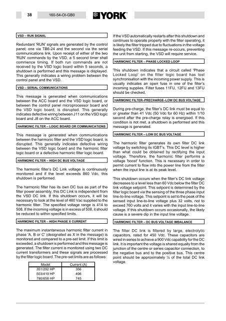
38 160-54-OI-GB0<br />
VSD – RUN SIGNAL<br />
Redundant 'RUN' signals are generated by the control<br />
panel; one via TB6-24 and the second via the serial<br />
communications link. Upon receipt of either of the two<br />
'RUN' commands by the VSD, a 5 second timer shall<br />
commence timing. If both run commands are not<br />
received by the VSD logic board within 5 seconds, a<br />
shutdown is performed and this message is displayed.<br />
This generally indicates a wiring problem between the<br />
control panel and the VSD.<br />
VSD – SERIALCOMMUNICATIONS<br />
This message is generated when communications<br />
between the ACC board and the VSD logic board, or<br />
between the control panel microprocessor board and<br />
the VSD logic board, is disrupted. This generally<br />
indicates defective wiring between J11 on the VSD logic<br />
board and J8 on the ACC board.<br />
HARMONIC FILTER – LOGIC BOARD OR COMMUNICATIONS<br />
This message is generated when communications<br />
between the harmonic filter and the VSD logic board, is<br />
disrupted. This generally indicates defective wiring<br />
between the VSD logic board and the harmonic filter<br />
logic board or a defective harmonic filter logic board.<br />
HARMONIC FILTER – HIGH DC BUS VOLTAGE<br />
The harmonic filter’s DC Link voltage is continuously<br />
monitored and if the level exceeds 860 Vdc, this<br />
shutdown is performed.<br />
The harmonic filter has its own DC bus as part of the<br />
filter power assembly, this DC Link is independent from<br />
the VSD DC link. If this shutdown occurs, it will be<br />
necessary to look at the level of 460 Vac supplied to the<br />
harmonic filter. The specified voltage range is 414 to<br />
508. If the incoming voltage is in excess of 508, it should<br />
be reduced to within specified limits.<br />
HARMONIC FILTER – HIGH PHASE X CURRENT<br />
The maximum instantaneous harmonic filter current in<br />
phase 'A, B or C' (designated as X in the message) is<br />
monitored and compared to a pre-set limit. If this limit is<br />
exceeded, a shutdown is performed and this message is<br />
generated. The filter current is monitored using two DC<br />
current transformers and these signals are processed<br />
by the filter logic board. The pre-set limits are as follows:<br />
Model Current (A)<br />
351/292 HP 356<br />
503/419 HP 496<br />
790/658 HP 745<br />
If the VSD automatically restarts after this shutdown and<br />
continues to operate properly with the filter operating, it<br />
is likely the filter tripped due to fluctuations in the voltage<br />
feeding the VSD. If this message re-occurs, preventing<br />
the unit from starting, the VSD will require service.<br />
HARMONIC FILTER – PHASE LOCKED LOOP<br />
This shutdown indicates that a circuit called 'Phase<br />
Locked Loop' on the filter logic board has lost<br />
synchronisation with the incoming power supply. This is<br />
usually indicates an open fuse in one of the filter’s<br />
incoming supplies. Filter fuses 11FU, 12FU and 13FU<br />
should be checked.<br />
HARMONIC FILTER–PRECHARGE–LOW DC BUS VOLTAGE<br />
During pre-charge, the filter’s DC link must be equal to<br />
or greater than 41 Vdc (50 Vdc for 60 Hz) within 1/10<br />
second after the pre-charge relay is energised. If this<br />
condition is not met, a shutdown is performed and this<br />
message is generated.<br />
HARMONIC FILTER – LOW DC BUS VOLTAGE<br />
The harmonic filter generates its own filter DC link<br />
voltage by switching its IGBT’s. This DC level is higher<br />
than what could be obtained by rectifying the input<br />
voltage. Therefore, the harmonic filter performs a<br />
voltage 'boost' function. This is necessary in order to<br />
permit current to flow into the power line from the filter<br />
when the input line is at its peak level.<br />
This shutdown occurs when the filter’s DC link voltage<br />
decreases to a level less than 60 Vdc below the filter DC<br />
link voltage setpoint. This setpoint is determined by the<br />
filter logic board via the sensing of the three phase input<br />
line-to-line voltage. This setpoint is set to the peak of the<br />
sensed input line-to-line voltage plus 32volts, not to<br />
exceed 760 volts and it varies with the input line-to-line<br />
voltage. If this shutdown occurs occasionally, the likely<br />
cause is a severe dip in the input line voltage.<br />
HARMONIC FILTER – DC BUS VOLTAGE IMBALANCE<br />
The filter DC link is filtered by large, electrolytic<br />
capacitors, rated for 450 Vdc. These capacitors are<br />
wired in series to achieve a 900 Vdc capability for the DC<br />
link. It is important the voltage is shared equally from the<br />
junction of the centre or series capacitor connection, to<br />
the negative bus and to the positive bus. This centre<br />
point should be approximately ½ of the total DC link<br />
voltage.



![[PDF] •Outdoor installation 4-5 - Johnson Controls](https://img.yumpu.com/10374038/1/184x260/pdf-ooutdoor-installation-4-5-johnson-controls.jpg?quality=85)
![[PDF] The European Products Catalogue 2012 - Johnson Controls](https://img.yumpu.com/3624903/1/184x260/pdf-the-european-products-catalogue-2012-johnson-controls.jpg?quality=85)