

YK CENTRIFUGAL LIQUID CHILLER OptiView ... - Johnson Controls
YK CENTRIFUGAL LIQUID CHILLER OptiView ... - Johnson Controls
YK CENTRIFUGAL LIQUID CHILLER OptiView ... - Johnson Controls

You also want an ePaper? Increase the reach of your titles
YUMPU automatically turns print PDFs into web optimized ePapers that Google loves.
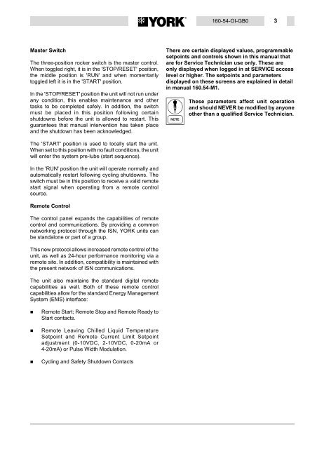
Master Switch<br />
The three-position rocker switch is the master control.<br />
When toggled right, it is in the 'STOP/RESET' position,<br />
the middle position is 'RUN' and when momentarily<br />
toggled left it is in the 'START' position.<br />
In the 'STOP/RESET' position the unit will not run under<br />
any condition, this enables maintenance and other<br />
tasks to be completed safely. In addition, the switch<br />
must be placed in this position following certain<br />
shutdowns before the unit is allowed to restart. This<br />
guarantees that manual intervention has taken place<br />
and the shutdown has been acknowledged.<br />
The 'START' position is used to locally start the unit.<br />
When set to this position with no fault conditions, the unit<br />
will enter the system pre-lube (start sequence).<br />
In the 'RUN' position the unit will operate normally and<br />
automatically restart following cycling shutdowns. The<br />
switch must be in this position to receive a valid remote<br />
start signal when operating from a remote control<br />
source.<br />
Remote Control<br />
The control panel expands the capabilities of remote<br />
control and communications. By providing a common<br />
networking protocol through the ISN, YORK units can<br />
be standalone or part of a group.<br />
This new protocol allows increased remote control of the<br />
unit, as well as 24-hour performance monitoring via a<br />
remote site. In addition, compatibility is maintained with<br />
the present network of ISN communications.<br />
The unit also maintains the standard digital remote<br />
capabilities as well. Both of these remote control<br />
capabilities allow for the standard Energy Management<br />
System (EMS) interface:<br />
Remote Start; Remote Stop and Remote Ready to<br />
Start contacts.<br />
Remote Leaving Chilled Liquid Temperature<br />
Setpoint and Remote Current Limit Setpoint<br />
adjustment (0-10VDC, 2-10VDC, 0-20mA or<br />
4-20mA) or Pulse Width Modulation.<br />
Cycling and Safety Shutdown Contacts<br />
160-54-OI-GB0 3<br />
There are certain displayed values, programmable<br />
setpoints and controls shown in this manual that<br />
are for Service Technician use only. These are<br />
only displayed when logged in at SERVICE access<br />
level or higher. The setpoints and parameters<br />
displayed on these screens are explained in detail<br />
in manual 160.54-M1.<br />
These parameters affect unit operation<br />
and should NEVER be modified by anyone<br />
other than a qualified Service Technician.


![[PDF] •Outdoor installation 4-5 - Johnson Controls](https://img.yumpu.com/10374038/1/184x260/pdf-ooutdoor-installation-4-5-johnson-controls.jpg?quality=85)

![[PDF] The European Products Catalogue 2012 - Johnson Controls](https://img.yumpu.com/3624903/1/184x260/pdf-the-european-products-catalogue-2012-johnson-controls.jpg?quality=85)