Sony SR-R4 Operation Manual - Talamas Broadcast Equipment
Sony SR-R4 Operation Manual - Talamas Broadcast Equipment
Sony SR-R4 Operation Manual - Talamas Broadcast Equipment

Create successful ePaper yourself
Turn your PDF publications into a flip-book with our unique Google optimized e-Paper software.
<strong>SR</strong>-<strong>R4</strong><br />
(SY)<br />
4-412-781-01 (1)<br />
<strong>Sony</strong> Corporation<br />
Printed on recycled paper.<br />
Printed in Japan<br />
2011.11 32<br />
© 2011<br />
PORTABLE MEMORY RECORDER<br />
<strong>SR</strong>-<strong>R4</strong><br />
CONTROL PANEL<br />
<strong>SR</strong>K-CP1<br />
OPERATION MANUAL [English]<br />
1st Edition
2<br />
Before operating the unit, please read this<br />
manual thoroughly and retain it for future<br />
reference.<br />
WARNING<br />
To reduce the risk of fire or<br />
electric shock, do not<br />
expose this apparatus to<br />
rain or moisture.<br />
To avoid electrical shock,<br />
do not open the cabinet.<br />
Refer servicing to qualified<br />
personnel only.<br />
Do not install the appliance in a confined<br />
space, such as book case or built-in cabinet.<br />
IMPORTANT<br />
The nameplate is located on the bottom of<br />
the left side.<br />
WARNING<br />
Excessive sound pressure from earphones<br />
and headphones can cause hearing loss.<br />
In order to use this product safely, avoid<br />
prolonged listening at excessive sound<br />
pressure levels.<br />
Caution<br />
Use of controls or adjustments or<br />
performance of procedures other than those<br />
specified herein may result in hazardous<br />
radiation exposure.<br />
This HD Portable Memory Recorder is<br />
classified as a CLASS 1 LASER PRODUCT.<br />
Laser Diode Properties<br />
Wavelength: 850 nm<br />
Emission duration: Pulse modulation<br />
Laser output power: 4 mW/channel (max)<br />
Standard: IEC60825-1 (2007)<br />
Egenskaber for laserdiode<br />
Bølgelængde: 850 nm<br />
Strålingsvarighed: Pulsmodulering<br />
Afgivet lasereffekt: 4 mW/kanal (maks.)<br />
Standard: IEC60825-1 (2007)<br />
Laserdiod - Egenskaper<br />
Våglängd: 850 nm<br />
Strålningens varaktighet: Pulsmodulation<br />
Lasereffekt: 4 mW/kanal (max)<br />
Standard: IEC60825-1 (2007)<br />
Egenskaper for laserdiode<br />
Bølgelengde: 850 nm<br />
Strålingsvarighet: Pulsmodulasjon<br />
Utgangseffekt for laser: 4 mW / kanal (maks.)<br />
Standard: IEC60825-1 (2007)<br />
VAROITUS!<br />
LAITTEEN KÄYTTÄMINEN MUULLA KUIN<br />
TÄSSÄ KÄYTTÖOHJEESSA MAINITULLA<br />
TAVALLA SAATTAA ALTISTAA<br />
KÄYTTÄJÄN TURVALLISUUSLUOKAN 1<br />
YLITTÄVÄLLE NÄKYMÄTTÖMÄLLE<br />
LASERSÄTEILYLLE.<br />
VARNING<br />
OM APPARATEN ANVÄNDS PÅ ANNAT<br />
SÄTT ÄN I DENNA BRUKSANVISNING<br />
SPECIFICERATS, KAN ANVÄNDAREN<br />
UTSÄTTAS FÖR OSYNLIG<br />
LASERSTRÅLNING, SOM ÖVERSKRIDER<br />
GRÄNSEN FÖR LASERKLASS 1.<br />
Caution<br />
The use of optical instruments with this<br />
product will increase eye hazard.
For the customers in the U.S.A.<br />
This equipment has been tested and found<br />
to comply with the limits for a Class A digital<br />
device, pursuant to Part 15 of the FCC<br />
Rules. These limits are designed to provide<br />
reasonable protection against harmful<br />
interference when the equipment is operated<br />
in a commercial environment. This<br />
equipment generates, uses, and can radiate<br />
radio frequency energy and, if not installed<br />
and used in accordance with the instruction<br />
manual, may cause harmful interference to<br />
radio communications. <strong>Operation</strong> of this<br />
equipment in a residential area is likely to<br />
cause harmful interference in which case the<br />
user will be required to correct the<br />
interference at his own expense.<br />
You are cautioned that any changes or<br />
modifications not expressly approved in this<br />
manual could void your authority to operate<br />
this equipment.<br />
All interface cables used to connect<br />
peripherals must be shielded in order to<br />
comply with the limits for a digital device<br />
pursuant to Subpart B of Part 15 of FCC<br />
Rules.<br />
This device complies with Part 15 of the FCC<br />
Rules. <strong>Operation</strong> is subject to the following<br />
two conditions: (1) this device may not cause<br />
harmful interference, and (2) this device<br />
must accept any interference received,<br />
including interference that may cause<br />
undesired operation.<br />
For the customers in Canada<br />
This Class A digital apparatus complies with<br />
Canadian ICES-003.<br />
For the customers in Europe<br />
This product with the CE marking complies<br />
with the EMC Directive issued by the<br />
Commission of the European Community.<br />
Compliance with this directive implies<br />
conformity to the following European<br />
standards:<br />
EN55103-1 : Electromagnetic<br />
Interference (Emission)<br />
EN55103-2 : Electromagnetic<br />
Susceptibility (Immunity)<br />
This product is intended for use in the<br />
following Electromagnetic Environments: E1<br />
(residential), E2 (commercial and light<br />
industrial), E3 (urban outdoors), E4<br />
(controlled EMC environment, ex. TV<br />
studio).<br />
For the customers in Europe<br />
The manufacturer of this product is <strong>Sony</strong><br />
Corporation, 1-7-1 Konan, Minato-ku,<br />
Tokyo, Japan.<br />
The Authorized Representative for EMC and<br />
product safety is <strong>Sony</strong> Deutschland GmbH,<br />
Hedelfinger Strasse 61, 70327 Stuttgart,<br />
Germany. For any service or guarantee<br />
matters please refer to the addresses given<br />
in separate service or guarantee documents.<br />
For the State of California, USA only<br />
Perchlorate Material - special handling may<br />
apply, See<br />
www.dtsc.ca.gov/hazardouswaste/<br />
perchlorate<br />
Perchlorate Material : Lithium battery<br />
contains perchlorate.<br />
For the customers in Taiwan only<br />
3
4<br />
Avant d’utiliser l’appareil, veuillez lire<br />
attentivement ce manuel et le conserver<br />
pour future référence.<br />
AVERTISSEMENT<br />
Afin de réduire les risques<br />
d’incendie ou<br />
d’électrocution, ne pas<br />
exposer cet appareil à la<br />
pluie ou à l’humidité.<br />
Afin d’écarter tout risque<br />
d’électrocution, garder le<br />
coffret fermé. Ne confier<br />
l’entretien de l’appareil<br />
qu’à un personnel qualifié.<br />
Ne pas installer l’appareil dans un endroit<br />
confiné, par exemple une bibliothèque ou un<br />
placard encastré.<br />
IMPORTANT<br />
La plaque signalétique se situe sous le<br />
panneau de gauche.<br />
AVERTISSEMENT<br />
Une pression acoustique excessive en<br />
provenance des écouteurs ou du casque<br />
peut provoquer une baisse de l’acuité<br />
auditive.<br />
Pour utiliser ce produit en toute sécurité,<br />
évitez l’écoute prolongée à des pressions<br />
sonores excessives.<br />
Enregistreur mémoire portable HD est<br />
classée comme PRODUIT LASER DE<br />
CLASSE 1.<br />
Pour les clients au Canada<br />
Cet appareil numérique de la classe A est<br />
conforme à la norme NMB-003 du Canada.<br />
Pour les clients en Europe<br />
Ce produit portant la marque CE est<br />
conforme à la Directive sur la compatibilité<br />
électromagnétique (EMC) émise par la<br />
Commission de la Communauté<br />
européenne.<br />
La conformité à cette directive implique la<br />
conformité aux normes européennes<br />
suivantes :<br />
EN55103-1 : Interférences<br />
électromagnétiques (émission)<br />
EN55103-2 : Sensibilité<br />
électromagnétique (immunité)<br />
Ce produit est prévu pour être utilisé dans<br />
les environnements électromagnétiques<br />
suivants : E1 (résidentiel), E2 (commercial et<br />
industrie légère), E3 (urbain extérieur) et E4<br />
(environnement EMC contrôlé, ex. studio de<br />
télévision).<br />
Pour les clients en Europe<br />
Le fabricant de ce produit est <strong>Sony</strong><br />
Corporation, 1-7-1 Konan, Minato-ku,<br />
Tokyo, Japon.<br />
Le représentant autorisé pour EMC et la<br />
sécurité des produits est <strong>Sony</strong> Deutschland<br />
GmbH, Hedelfinger Strasse 61, 70327<br />
Stuttgart, Allemagne. Pour toute question<br />
concernant le service ou la garantie, veuillez<br />
consulter les adresses indiquées dans les<br />
documents de service ou de garantie<br />
séparés.
Bitte lesen Sie dieses Handbuch vor der<br />
Benutzung des Geräts sorgfältig durch und<br />
bewahren Sie es zum späteren<br />
Nachschlagen auf.<br />
WARNUNG<br />
Um die Gefahr von Bränden<br />
oder elektrischen Schlägen<br />
zu verringern, darf dieses<br />
Gerät nicht Regen oder<br />
Feuchtigkeit ausgesetzt<br />
werden.<br />
Um einen elektrischen<br />
Schlag zu vermeiden, darf<br />
das Gehäuse nicht geöffnet<br />
werden. Überlassen Sie<br />
Wartungsarbeiten stets nur<br />
qualifiziertem<br />
Fachpersonal.<br />
Das Gerät nicht an Orten aufstellen, z.B. in<br />
Bücherregalen oder Einbauschränken, wo<br />
keine ausreichende Belüftung gewährleistet<br />
ist.<br />
WICHTIG<br />
Das Namensschild befindet sich auf der<br />
Unterseite der linken Wand.<br />
WARNUNG<br />
Zu hoher Schalldruck von Ohrhörern und<br />
Kopfhörern kann Gehörschäden<br />
verursachen.<br />
Um dieses Produkt sicher zu verwenden,<br />
vermeiden Sie längeres Hören bei sehr<br />
hohen Schalldruckpegeln.<br />
Dieser Tragbarer HD-Speicherrecorder ist<br />
als LASERPRODUKT DER KLASSE 1<br />
eingestuft.<br />
Daten der Laserdiode<br />
Wellenlänge: 850 nm<br />
Emissionsdauer: Pulsmodulation<br />
Laser-Ausgangsleistung: 4 mW/Kanal (max.)<br />
Standard: IEC60825-1 (2007)<br />
Für Kunden in Europa<br />
Dieses Produkt besitzt die CE-<br />
Kennzeichnung und erfüllt die EMV-<br />
Richtlinie der EG-Kommission.<br />
Angewandte Normen:<br />
EN55103-1: Elektromagnetische<br />
Verträglichkeit (Störaussendung)<br />
EN55103-2: Elektromagnetische<br />
Verträglichkeit (Störfestigkeit)<br />
Für die folgenden elektromagnetischen<br />
Umgebungen: E1 (Wohnbereich), E2<br />
(kommerzieller und in beschränktem Maße<br />
industrieller Bereich), E3 (Stadtbereich im<br />
Freien) und E4 (kontrollierter EMV-Bereich,<br />
z.B. Fernsehstudio).<br />
5
6<br />
Für Kunden in Europa<br />
Der Hersteller dieses Produkts ist <strong>Sony</strong><br />
Corporation, 1-7-1 Konan, Minato-ku,<br />
Tokyo, Japan.<br />
Der autorisierte Repräsentant für EMV und<br />
Produktsicherheit ist <strong>Sony</strong> Deutschland<br />
GmbH, Hedelfinger Strasse 61, 70327<br />
Stuttgart, Deutschland. Bei jeglichen<br />
Angelegenheiten in Bezug auf Kundendienst<br />
oder Garantie wenden Sie sich bitte an die in<br />
den separaten Kundendienst- oder<br />
Garantiedokumenten aufgeführten<br />
Anschriften.
Table of Contents<br />
Chapter 1 : Overview<br />
Features................................................... 9<br />
System Configuration Example ............ 9<br />
Names of Parts...................................... 10<br />
Overall View ............................. 10<br />
Left Side View........................... 10<br />
Rear and Right Side View......... 11<br />
Control Panel<br />
(<strong>SR</strong>K-CP1, Option)............. 12<br />
Display...................................... 13<br />
Chapter 2 : Preparation<br />
Work Flow ............................................ 15<br />
Mount Control Panel on Unit ............. 15<br />
Connect F65.......................................... 17<br />
Mount Control Panel on the F65 ........ 19<br />
Attach the Battery Pack ...................... 20<br />
Turn Power On .................................... 21<br />
Insert <strong>SR</strong>Memory Card ..................... 22<br />
Formatting an <strong>SR</strong>Memory Card<br />
(File System Format) .......... 23<br />
Chapter 3 : Basic Menu <strong>Operation</strong>s<br />
Buttons Used for Menu<br />
<strong>Operation</strong>s ........................... 25<br />
Serve for Selecting a Menu ....... 25<br />
Locking the Controls................. 26<br />
Signal Format Settings ........................ 27<br />
Selecting the Signal Format ...... 27<br />
<strong>Operation</strong> Mode Settings..................... 28<br />
Display Settings .................................... 28<br />
Using the Backlight................... 28<br />
Using the Screen Saver.............. 28<br />
Date Settings ......................................... 29<br />
Chapter 4 : Recording and Playback<br />
Recording Preparations and<br />
<strong>Operation</strong>s ...................................... 30<br />
Setting the Audio Signals .......... 30<br />
Setting the Recording Levels..... 31<br />
Setting the Time Code and User<br />
Bits ..................................... 32<br />
To set the operation mode ......... 34<br />
Recording .................................. 34<br />
Playback Preparations and<br />
<strong>Operation</strong>s ...................................... 35<br />
Making Settings Related to Audio<br />
Monitor Signals................... 35<br />
Adjusting Playback Audio<br />
Levels ................................. 35<br />
Selecting the Time Data to Display<br />
During Playback.................. 35<br />
To set the operation mode ......... 36<br />
Playback .................................... 36<br />
How to Use the Recording and Playback<br />
<strong>Operation</strong> Buttons.......................... 37<br />
FILE LIST <strong>Operation</strong>s ........................ 38<br />
Displaying a File List ................ 38<br />
Performing File <strong>Operation</strong>s ....... 39<br />
Changing the File Display<br />
Order ................................... 39<br />
Chapter 5 : Menu Details<br />
TC Setup Menu .................................... 40<br />
VIDEO Setup Menu............................. 42<br />
AUDIO Setup Menu............................. 43<br />
SYSTEM Setup Menu ......................... 45<br />
Table of Contents 7
8<br />
Appendix<br />
Maintenance and Inspections.............. 48<br />
Note About the CAMERA<br />
Connector............................ 48<br />
Cleaning the CAMERA<br />
Connector............................ 48<br />
Specifications ........................................ 50<br />
General ...................................... 50<br />
Video ......................................... 50<br />
Audio......................................... 50<br />
Input/Output Connectors ........... 50<br />
Supplied Accessories................. 51<br />
Optional Accessories................. 51<br />
Error Messages and Warning<br />
Messages ......................................... 52<br />
About Error Messages............... 52<br />
About Warning Messages ......... 52<br />
Warning System ................................... 53<br />
Troubleshooting ................................... 54<br />
About Recording/Playback Formats.. 57<br />
Index...................................................... 58<br />
Table of Contents
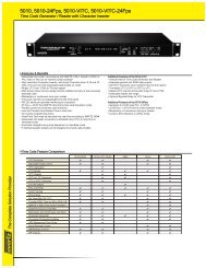
Chapter 1 Overview<br />
Features System Configuration<br />
Example<br />
The <strong>SR</strong>-<strong>R4</strong> is a portable memory recorder of the<br />
<strong>SR</strong>MASTER series, featuring an F65 dockable<br />
CAMERA port and using the newly developed<br />
<strong>SR</strong>Memory card for the recording media.<br />
<strong>SR</strong>MASTER and <strong>SR</strong>Memory are trademarks of<br />
<strong>Sony</strong> Corporation.<br />
F65RAW Recording<br />
Supports F65RAW recording.<br />
There is 16-channel (uncompressed, 24-bit,<br />
48 kHz) support for audio.<br />
F65 dockable operation<br />
Supports dockable operation in combination with<br />
the F65.<br />
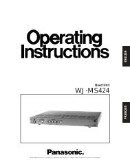
The following figure shows a system configured<br />
around the <strong>SR</strong>-<strong>R4</strong>.<br />
HD color video camera<br />
CTRL PANEL<br />
F65<br />
<strong>SR</strong>-<strong>R4</strong><br />
dB SDI SDI SDI SDI SDI SDI SDI SDI SDI SDI SDI SDI SDI SDI SDI SDI<br />
0<br />
KEY INHI<br />
-10<br />
HOME<br />
-20<br />
OFF ON<br />
-30<br />
SELECT/ENTER<br />
-60<br />
EMP EMP EMP EMP EMP EMP EMP EMP EMP EMP EMP EMP EMP EMP EMP EMP<br />
TC<br />
EE<br />
LIGHT<br />
L R L R L R L R L R L R L R L R L R L R L R L R L R L R L R L R<br />
BACK<br />
1 2 3 4 5 6 7 8 9 10 11 12 13 14 15 16 OFF ON<br />
VIDEO<br />
STOP<br />
<strong>SR</strong>-<strong>R4</strong>:CAM<br />
ADJUST<br />
TCG<br />
KEYINHI<br />
RECINHI<br />
AUDIO<br />
EJECT STOP PLAY REC<br />
Z x<br />
B<br />
z<br />
00 H00 M00 S00 F<br />
SYSTEM<br />
16.5V REMAIN ENCODE F65RAW LOCAL<br />
REW F FWD PAUSE<br />
FUNC<br />
STANDARD M 23P EE<br />
m M<br />
X<br />
10min<br />
21:46<br />
Control Panel (<strong>SR</strong>K-CP1, option)<br />
Earphones/Headphones<br />
Audio input<br />
Microphone<br />
Analog: 2 channels<br />
Features / System Configuration Example 9<br />
Chapter 1 Overview
Chapter 1 Overview<br />
10<br />
Names of Parts<br />
For detailed information on functions and usage, see<br />
the pages indicated in brackets.<br />
Overall View<br />
1<br />
7 6<br />
5<br />
1. Lid open/close button (page 22)<br />
2. Tally indicator (page 22)<br />
Lights up during recording.<br />
Flashes as a warning indication when an<br />
error or problem has occurred.<br />
3. POWER (power supply) indicator<br />
(page 21)<br />
Lights up in green when power to the unit is<br />
on.<br />
4. EJECT button (page 23)<br />
5. <strong>SR</strong>Memory card slot (page 22)<br />
6. Docking screws (page 18)<br />
7. LID LOCK indicator (page 22)<br />
Lights up in orange when an <strong>SR</strong>Memory card<br />
is mounted.<br />
Names of Parts<br />
4<br />
2 3<br />
Left Side View<br />
1<br />
2<br />
9 8 7 6<br />
1. AUDIO INPUT CH-1, CH-2 (analog audio<br />
input channel 1, 2) connectors (3-pin XLR,<br />
female) and input selection switches<br />
Set the input selection switches as follows,<br />
depending on the type and level of the input<br />
audio.<br />
LINE: For line input<br />
MIC: For microphone input<br />
MIC +48V ON: For input from microphones<br />
with external power supply<br />
2. EARPHONES jack (stereo mini jack) and<br />
LEVEL knob<br />
Adjusts the audio level.<br />
A warning/alarm tone is also output via this<br />
jack when an error is detected.<br />
3. TC IN (time code input) connector (BNC)<br />
Connect to the time code output connector of<br />
an external device such as a time code<br />
generator or VTR. Use this connector when<br />
locking the internal time code generator to<br />
external time code.<br />
4. TC OUT (time code output) connector<br />
(BNC)<br />
Connect to the time code input connector of<br />
an external device such as a time code reader<br />
or VTR. Signal is supplied according to<br />
setting made from TC Setup menu, OTHERS<br />
>TC OUT. (see page 41)<br />
5. AUX IN (for future use)<br />
6. Docking screws (page 18)<br />
7. CAMERA connector (page 17)<br />
8. CTRL PANEL (Control Panel) connector<br />
(page 16)<br />
9. AUX OUT connector (for future use)<br />
3<br />
4 5
Rear and Right Side View<br />
1. Power switch (page 21)<br />
Setting the switch to the ? side turns power<br />
on, and setting the switch to the 1 side turns<br />
power off.<br />
2. Cable clamp (page 16)<br />
3. Fan<br />
Note<br />
1<br />
2<br />
Do not block the ventilation openings.<br />
Otherwise internal heat buildup can lead to a risk of<br />
fire and damage to the unit.<br />
3<br />
Chapter 1 Overview<br />
Names of Parts 11
Chapter 1 Overview<br />
12<br />
Control Panel (<strong>SR</strong>K-CP1, Option)<br />
For information on how to use the control panel, see “Basic Menu <strong>Operation</strong>s” (page 25).<br />
1<br />
HOME<br />
TC<br />
VIDEO<br />
AUDIO<br />
SYSTEM<br />
1. Menu selection buttons (page 25)<br />
For information on menu items, see “Menu<br />
Details” (page 40).<br />
2. Display (page 13)<br />
3. KEY INHI (key inhibit) switch (page 26)<br />
4. LIGHT switch (page 28)<br />
Setting this switch to ON turns the backlight<br />
on.<br />
5. ADJUST knob<br />
Serves to adjust audio levels etc.<br />
6. SELECT/ENTER dial (page 25)<br />
Serves to make menu selections etc. Rotate<br />
the dial to move the cursor and press the dial<br />
to change and confirm settings.<br />
7. BACK button (page 25)<br />
When a menu is displayed, you can press this<br />
button to back up one level in the menu<br />
structure.<br />
8. Control panel connection cable (page 16)<br />
9. Record/Play buttons (page 34, 36, 37)<br />
Use these buttons to play recordings and<br />
files.<br />
The functions of the buttons change when<br />
they are pressed together with the FUNC<br />
button.<br />
10. FUNC (Function) button (page 37)<br />
Holding down this button changes the<br />
operation of the Record/Play buttons.<br />
11. EJECT button and indicator (page 23)<br />
Names of Parts<br />
dB SDI SDI SDI SDI SDI SDI SDI SDI SDI SDI SDI SDI SDI SDI SDI SDI<br />
0<br />
-10<br />
-20<br />
-30<br />
-60<br />
EMP EMP EMP EMP EMP EMP EMP EMP EMP EMP EMP EMP EMP EMP EMP EMP<br />
EE<br />
L R L R L R L R L R L R L R L R L R L R L R L R L R L R L R L R<br />
1 2 3 4 5 6 7 8 9 10 11 12 13 14 15 16<br />
STOP<br />
<strong>SR</strong>-<strong>R4</strong>:CAM<br />
TCG<br />
KEYINHI<br />
RECINHI<br />
00 H00 M00 S00 F<br />
16.5V<br />
REMAIN<br />
10min<br />
2 3 4 5 6 7 8<br />
ENCODE<br />
STANDARD<br />
F65RAW<br />
23.98P<br />
LOCAL<br />
EE<br />
21:46<br />
KEY INHI<br />
OFF ON<br />
LIGHT<br />
OFF ON<br />
ADJUST<br />
EJECT STOP PLAY REC<br />
Z x<br />
B<br />
z<br />
FUNC<br />
SELECT/ENTER<br />
REW F FWD PAUSE<br />
m M<br />
X<br />
11 10 9<br />
Note on faulty pixels on the LCD panel<br />
The LCD panel fitted to this unit is manufactured<br />
with high precision technology, giving a<br />
functioning pixel ratio of at least 99.99%. Thus a<br />
very small proportion of pixels maybe “stuck”,<br />
either always off (black), always on (red, green,<br />
or blue), or flashing. In addition, over a long<br />
period of use, because of the physical<br />
characteristics of the liquid crystal display, such<br />
“stuck” pixels may appear spontaneously. These<br />
problems are not a malfunction. Note that any<br />
such problems have no effect on recorded data.<br />
BACK
Display<br />
The condition shown below is called the HOME screen in this manual.<br />
dB SDI SDI SDI SDI SDI SDI SDI SDI SDI SDI SDI SDI SDI SDI SDI SDI<br />
0<br />
-10<br />
-20<br />
-30<br />
-60<br />
EMP EMP EMP EMP EMP EMP EMP EMP EMP EMP EMP EMP EMP EMP EMP EMP<br />
EE<br />
L R L R L R L R L R L R L R L R L R L R L R L R L R L R L R L R<br />
1 2 3 4 5 6 7 8 9 10 11 12 13 14 15 16<br />
STOP<br />
<strong>SR</strong>-<strong>R4</strong>:CAM<br />
TCG<br />
KEYINHI<br />
RECINHI<br />
00 H00 M00 S00 F<br />
16.5V<br />
9<br />
REMAIN<br />
10min<br />
ENCODE<br />
STANDARD<br />
F65RAW<br />
23.98P<br />
LOCAL<br />
EE<br />
21:46<br />
1. Audio level meters<br />
Show the recording level in recording and E-<br />
E mode. During playback, the meters show<br />
the playback level.<br />
The top row indicates the audio input signal<br />
that is being recorded.<br />
The numbers 1 to 16 in the bottom row<br />
indicate the track number of the file.<br />
2. <strong>Operation</strong> status and warning indicator<br />
Shows the operation status of the unit as well<br />
as various warning indications.<br />
<strong>SR</strong>-<strong>R4</strong>:<br />
CAM<br />
8<br />
1<br />
7<br />
6<br />
5<br />
The background color is red<br />
when the unit is operating in<br />
recording mode, and blue when<br />
operating in playback mode.<br />
The mode is changed using<br />
RECORDER/PLAYER in the<br />
VIDEO Setup menu.<br />
TCR/TCG/ Time data type.<br />
UBR/UBG/<br />
TM1/TM2<br />
LTC/VITC Time code is being shown.<br />
DF/NDF System is in DF (drop-frame) or<br />
NDF (non-drop frame) mode.<br />
(see page 41)<br />
EXT-LK Time code is locked to external<br />
time code.<br />
KEY INHI KEY INHI switch is ON. (see<br />
page 26)<br />
2<br />
4 3<br />
Sections 4 to 7 change to the condition<br />
shown as 10 below when the HOME<br />
button is pressed while holding down the<br />
FUNC button.<br />
00 H00 M00 S00 F<br />
SYS: F65RAW 23.98P<br />
EMCODE: STANDARD<br />
PB: F65RAW 23.98P<br />
10<br />
LOCAL<br />
---<br />
16.5V<br />
REC INHI <strong>SR</strong>Memory card is writeprotected.<br />
(see page 23)<br />
3. <strong>SR</strong>Memory card icon indications<br />
Mounting/mounted<br />
An <strong>SR</strong>Memory card is inserted<br />
and the lid is locked.<br />
Unmounting (cursor section in the<br />
bottom right flashes)<br />
The EJECT button has been<br />
pressed and the unit is<br />
transitioning to the state in which<br />
you can remove the <strong>SR</strong>Memory<br />
card.<br />
UNMOUNT state<br />
The lid lock has been released and<br />
the <strong>SR</strong>Memory card can be<br />
removed.<br />
There is no <strong>SR</strong>Memory card in the<br />
unit. (off)<br />
4. Time data indication<br />
Shows the time data for the current position<br />
in the file.<br />
Chapter 1 Overview<br />
Names of Parts 13
Chapter 1 Overview<br />
14<br />
5. Status indication<br />
Shows the control mode of the unit<br />
(LOCAL), power mode (EE), and current<br />
time.<br />
Top row Shows LOCAL always.<br />
Bottom row Shows the current time.<br />
6. Signal format indication<br />
Shows the format of the signal being<br />
recorded.<br />
7. Encoding format indication (page 57)<br />
Shows the encoding and bit rate settings used<br />
for recording.<br />
8. <strong>SR</strong>Memory card remaining capacity<br />
indication<br />
Shows the remaining space on the<br />
<strong>SR</strong>Memory card calculated as remaining<br />
time, using the current recording settings.<br />
When the remaining time is less than 3<br />
minutes, the indication flashes.<br />
9. Power supply voltage indication (page 21)<br />
Shows the power supply voltage.<br />
10. Signal format indication (page 27)<br />
When the FUNC and HOME buttons are<br />
pressed simultaneously, the signal formats<br />
are displayed from top to bottom in system,<br />
encoding, playback file name sequence, or in<br />
playback file output, recording date, duration<br />
sequence.<br />
Names of Parts<br />
To switch display to portrait mode<br />
Press the HOME button while holding down the<br />
FUNC and BACK buttons to switch the display to<br />
portrait mode (rotate display 90° to the left).<br />
To return to landscape mode, press the HOME<br />
button again while holding down the FUNC and<br />
BACK buttons.<br />
SDI SDI SDI SDI SDI SDI SDI SDI SDI SDI SDI SDI SDI SDI SDI SDI<br />
EM EM EM EM EM EM EM EM EM EM EM EM EM EM EM EM<br />
L R L R L R L R L R L R L R L R L R L R L R L R L R L R L R L R<br />
1 2 3 4 5 6 7 8 9 10 11 12 13 14 15 16<br />
<strong>SR</strong>-<strong>R4</strong>:CAM<br />
KEYINHI<br />
RECINHI<br />
STOP<br />
TCG<br />
00 H00 M04 S22 F<br />
SYS:F65RAW 23.98P<br />
ENCODE:STANDARD<br />
FILENAME:<br />
16.7V<br />
REMAIN<br />
77min<br />
F65RAW<br />
23.98P<br />
LOCAL<br />
EE<br />
19:47
Chapter 2 Preparation<br />
Work Flow<br />
The steps that are required before starting to use<br />
the <strong>SR</strong>-<strong>R4</strong> are listed below.<br />
When mounting Control Panel (<strong>SR</strong>K-CP1,<br />
Option) on the unit<br />
Mount control panel on unit (page 15)<br />
Connect F65 (page 17)<br />
Turn power on (page 21)<br />
Insert <strong>SR</strong>Memory card (page 22)<br />
When mounting Control Panel (<strong>SR</strong>K-CP1,<br />
Option) on the F65<br />
Connect F65 (page 17)<br />
Mount control panel on the F65 (page 19)<br />
Turn power on (page 21)<br />
Insert <strong>SR</strong>Memory card (page 22)<br />
Tip<br />
A Phillips (cross head) screwdriver is required for<br />
mounting the control panel.<br />
Mount Control Panel on<br />
Unit<br />
Attach the CP bracket supplied with the Control<br />
Panel (<strong>SR</strong>K-CP1, Option) to the unit, and connect<br />
the unit and the control panel with the control<br />
panel cable.<br />
1 Attach the CP bracket supplied with the<br />
control panel to the right side of the<br />
unit.<br />
2 Slide the control panel into the CP<br />
bracket.<br />
Work Flow / Mount Control Panel on Unit 15<br />
Chapter 2 Preparation
Chapter 2 Preparation<br />
16<br />
3 Use the supplied control panel cable to<br />
connect the unit and the control panel.<br />
4 Use the cable clamp as shown, to fix the<br />
cable.<br />
Notes<br />
Do not cross the cord below the clamps.<br />
Make sure that the bottom of the cord does not<br />
extend beyond the bottom of the <strong>SR</strong>-<strong>R4</strong>.<br />
If the <strong>SR</strong>-<strong>R4</strong> cannot be docked on the F65, refer<br />
to the above and check the cord bundle again.<br />
Note<br />
Always turn off the power supply for the unit before<br />
disconnecting the control panel cable and removing the<br />
control panel.<br />
Mount Control Panel on Unit<br />
To remove the control panel<br />
Grasp the underside of the CP bracket and push it<br />
in the B direction to release the lock. Then slide<br />
the control panel out.
Connect F65<br />
The unit mounts onto the rear of the F65.<br />
Tips<br />
When mounting the unit, first mount the F65 on<br />
a tripod and secure it such that it does not move.<br />
For details of mounting on a tripod, refer to the<br />
<strong>Operation</strong> <strong>Manual</strong> for the F65.<br />
When mounting the unit, do so in an<br />
environment relatively free from dust, etc.<br />
1 Remove the connector cap from the<br />
CAMERA connector of the unit.<br />
Tip<br />
Store the connector cap in a safe location so that you<br />
do not lose it.<br />
2 Align and connect the CAMERA<br />
connector of the unit with the F65<br />
connector.<br />
First, join as shown.<br />
1 Align the base of the unit with the base<br />
of the F65 as shown in the diagram.<br />
Couple the unit in the orientation shown.<br />
2 Align the CAMERA connector of the<br />
unit with the F65 dock connector, and<br />
push the unit down.<br />
Chapter 2 Preparation<br />
Connect F65 17
Chapter 2 Preparation<br />
18<br />
3 Press down firmly on the point shown in<br />
the diagram, and fasten the docking<br />
screws.<br />
Note<br />
Do not push down on the lid.<br />
Tip<br />
You can leave the connector cap, which was<br />
removed from the CAMERA connector, attached to<br />
the docking screws.<br />
Connector cap<br />
Connect F65<br />
Removing the Unit from the F65<br />
1 Press down firmly on the point shown in<br />
the diagram, and loosen the docking<br />
screws.<br />
2 Remove the unit by lifting it.<br />
When lifting, hold the unit as close as<br />
possible to the F65 and pull it up.<br />
Note<br />
Do not push on the ventilation openings.<br />
3 Attach the connector cap to the<br />
CAMERA connector of the unit.
Mount Control Panel on<br />
the F65<br />
Attach the Control Panel (<strong>SR</strong>K-CP1, Option) to<br />
the F65, and connect the unit and the control<br />
panel with the control panel cable.<br />
1 Attach the outside bracket supplied<br />
with the control panel to the side of the<br />
F65, and fasten using the 4 supplied<br />
screws (M3 × 5).<br />
There are 2 types of outside bracket. Attach<br />
the larger outside bracket to an F65 with a<br />
mechanical shutter or the smaller outside<br />
bracket to an F65 without a mechanical<br />
shutter.<br />
Screws (M3 × 5)<br />
2 Attach the CP Bracket to the outside<br />
bracket.<br />
3 Slide the control panel into the CP<br />
bracket.<br />
4 Use the supplied control panel cable to<br />
connect the unit and the control panel.<br />
5 Use the cable clamp as shown to fix the<br />
cable.<br />
Note<br />
Always turn off the power supply for the unit before<br />
disconnecting the control panel cable and removing<br />
the control panel.<br />
Mount Control Panel on the F65 19<br />
Chapter 2 Preparation
Chapter 2 Preparation<br />
20<br />
To remove the control panel<br />
Grasp the underside of the CP bracket and push it<br />
in the B direction to release the lock. Then slide<br />
the control panel out.<br />
Attach the Battery Pack<br />
Attach the Battery Pack<br />
To attach the battery pack, the following options<br />
must be installed using the BKP spacer supplied<br />
with the unit.<br />
BKP-L551 battery pack adapter (power supply<br />
for accessories)<br />
Battery adapter for the F65 (power supply for<br />
the F65, scheduled for release)<br />
Note<br />
Power cannot be supplied directly to the unit from the<br />
battery pack.<br />
1 Remove the top cover of the unit.
2 Attach the supplied BKP spacer.<br />
The S symbol must face up.<br />
3 Attach the BKP-L551 using the screw<br />
holes labeled with an S symbol, and<br />
fasten.<br />
To accessory<br />
S symbols<br />
BKP-L551 fastening L screws<br />
BKP-L551 fastening L wrench<br />
Turn Power On<br />
To power up the unit<br />
1 Press the power switch on the <strong>SR</strong>-<strong>R4</strong> on<br />
the ? side.<br />
2 Set the F65 POWER OFF/ON switch to<br />
ON.<br />
The power comes on together with the F65<br />
and the POWER indicator lights up in green.<br />
To power down the unit<br />
1 Set the F65 POWER OFF/ON switch to<br />
OFF.<br />
The power is turned off together with the F65<br />
and the POWER indicator goes out.<br />
Note<br />
To prevent the risk of data corruption, do not interrupt<br />
the F65 DC IN power supply while the <strong>SR</strong>-<strong>R4</strong> is turned<br />
on.<br />
Tip<br />
If power is turned off while an <strong>SR</strong>Memory card is<br />
mounted, the unit will not power down immediately, to<br />
protect the data on the card. The <strong>SR</strong>Memory card will be<br />
unmounted first, and then the unit powers down.<br />
Checking the power/voltage<br />
The indication at the bottom left of the control<br />
panel display serves to verify the battery status or<br />
the voltage of the external power supply.<br />
However, this indication is not based on the<br />
actual connection condition but on the setting<br />
made under SYSTEM Setup > BATTERY ><br />
DCIN TYPE. (see page 46)<br />
Set DCIN TYPE to match the power supply used<br />
by the F65.<br />
Tips<br />
When signal format is shown, the indication appears at<br />
bottom right.<br />
Chapter 2 Preparation<br />
Turn Power On 21
Chapter 2 Preparation<br />
22<br />
The voltage shown is the actual voltage used by the<br />
unit (this may be lower than the input voltage and the<br />
F65 DC IN connector).<br />
When a battery pack is selected<br />
The battery symbol is shown.<br />
16.5V<br />
When fully charged, all seven segments are lit.<br />
As the battery pack discharges, the segments go<br />
out from left to right.<br />
When the battery pack is almost exhausted<br />
(NEAR END), the voltage indication and the<br />
tally indicator start to flash, and an intermittent<br />
warning tone sounds in the earphones.<br />
When the battery pack is completely exhausted<br />
(END), the corresponding warning indication<br />
lights, the tally indicator starts to flash at a<br />
higher rate, and the earphones warning tone<br />
sounds continuously.<br />
Tip<br />
The DCIN TYPE option in the SYSTEM Setup menu<br />
allows you to set the battery voltages which trigger the<br />
NEAR END and END warnings. (see page 46)<br />
When AC power is selected<br />
The connector symbol is shown.<br />
16.5V<br />
Insert <strong>SR</strong>Memory Card<br />
Insert <strong>SR</strong>Memory Card<br />
Supported <strong>SR</strong>Memory cards<br />
The unit supports the following <strong>SR</strong>Memory<br />
cards.<br />
59.94p<br />
<strong>SR</strong>Memory card Recording time<br />
Unit: Minutes (approx.)<br />
23.97p<br />
Unit: Minutes (approx.)<br />
1) The recording time varies depending on the model<br />
and recording conditions.<br />
1)<br />
(F65RAW mode)<br />
<strong>SR</strong>-256S55<br />
6<br />
<strong>SR</strong>-512S55<br />
12<br />
<strong>SR</strong>Memory card Recording time1) (F65RAW mode)<br />
<strong>SR</strong>-256S55<br />
15<br />
<strong>SR</strong>-512S55<br />
30<br />
To insert the <strong>SR</strong>Memory card<br />
1 Press the lid open/close button to open<br />
the lid of the <strong>SR</strong>Memory card slot and<br />
insert the <strong>SR</strong>Memory card.<br />
Take care to insert the <strong>SR</strong>Memory card with<br />
the correct orientation.<br />
<strong>SR</strong>Memory card<br />
Tip<br />
If the LID LOCK indicator is lit in orange, showing<br />
that the lid is locked, press the EJECT button on the<br />
control panel to unmount the card first, and then<br />
open the lid.
2 Push the <strong>SR</strong>Memory card all the way in<br />
and close the lid.<br />
The <strong>SR</strong>Memory card is mounted, and the<br />
LID LOCK indicator lights up in orange.<br />
Verify that no error message is shown on the<br />
control panel display.<br />
Tip<br />
When closing the lid, make sure to close it all the<br />
way until it will go no further.<br />
If “XXX: SALVAGE DETECT” is shown on the<br />
display<br />
This indicates that the previous recording did not<br />
complete normally.<br />
For information on what to do in this case, see<br />
“Salvaging <strong>SR</strong>Memory cards for which recording<br />
did not complete properly” (page 54) in the<br />
“Troubleshooting” section.<br />
To remove the <strong>SR</strong>Memory card<br />
1 Press the EJECT button on the control<br />
panel while power to the unit is on or<br />
turn the power to the unit off.<br />
The files in the <strong>SR</strong>Memory card are closed<br />
automatically, the <strong>SR</strong>Memory card is<br />
unmounted, and the lock of the lid is<br />
released.<br />
During the unmount procedure, the indicator<br />
of the EJECT button on the control panel is<br />
lit.<br />
2 Press the lid open/close button to open<br />
the lid.<br />
3 Press the EJECT button on the right<br />
side of the slot to remove the<br />
<strong>SR</strong>Memory card.<br />
Pressing this button causes the <strong>SR</strong>Memory<br />
card to pop out.<br />
Write-protecting the card<br />
In order to prevent inadvertent erasure of<br />
recorded content, you can slide the write protect<br />
switch to “WP.”<br />
Write protect switch Slide<br />
fully to the right.<br />
When the card is inserted in the <strong>SR</strong>-<strong>R4</strong> in this<br />
condition, the indication “REC INHI” appears,<br />
and recording is not possible.<br />
To re-enable recording on this card, return the<br />
write protect switch to the original condition.<br />
Formatting an <strong>SR</strong>Memory Card<br />
(File System Format)<br />
<strong>SR</strong>Memory cards are sold already formatted, so<br />
you can use a newly purchased <strong>SR</strong>Memory card<br />
right away.<br />
To format an <strong>SR</strong>Memory card on which data were<br />
recorded, proceed as follows.<br />
Note<br />
Formatting will erase all files and data on the <strong>SR</strong>Memory<br />
card.<br />
For details on menu operation, see “Basic Menu<br />
<strong>Operation</strong>s” (page 25).<br />
1 Press the SYSTEM button.<br />
The SYSTEM Setup menu appears.<br />
Chapter 2 Preparation<br />
Insert <strong>SR</strong>Memory Card 23
Chapter 2 Preparation<br />
24<br />
2 Select and confirm “<strong>SR</strong>Memory” t<br />
select and confirm “FORMAT” t<br />
move the cursor to [OK] and confirm<br />
while pressing the FUNC button.<br />
The file system formatting process starts.<br />
When the process is finished, the indication<br />
“Completed” is shown.<br />
3 Return to the HOME screen. (see<br />
page 26)<br />
Insert <strong>SR</strong>Memory Card
Chapter 3 Basic Menu <strong>Operation</strong>s<br />
The menu system of the <strong>SR</strong>-<strong>R4</strong> consists of the<br />
following four menus.<br />
Menu Overview<br />
TC Setup Serves for making time code<br />
settings.<br />
AUDIO Setup Serves for making audio signal<br />
related settings.<br />
SYSTEM Setup Serves for making system<br />
settings.<br />
For details on menu items, see “Menu Details”<br />
(page 40).<br />
The menu is operated with the control panel.<br />
Buttons Used for Menu <strong>Operation</strong>s<br />
HOME button SELECT/ENTER dial<br />
BACK button<br />
HOME<br />
TC<br />
VIDEO<br />
AUDIO<br />
SYSTEM<br />
TC Setup<br />
TIMER SEL<br />
TIMER RESET<br />
TIMER PRESET<br />
TCR SEL<br />
TCG MODE<br />
RUN MODE<br />
TCG SET<br />
OTHERS<br />
TC<br />
LTC<br />
PRST<br />
R RUN<br />
<strong>SR</strong>-<strong>R4</strong>:CAM STOP<br />
TCR 00:00:00:00<br />
Menu selection buttons<br />
KEY INHI<br />
OFF ON<br />
LIGHT<br />
OFF ON<br />
EJECT STOP PLAY<br />
Z x<br />
B<br />
REC<br />
z<br />
FUNC<br />
ADJUST<br />
SELECT/ENTER<br />
REW F FWD PAUSE<br />
m M<br />
X<br />
BACK<br />
Serve for Selecting a Menu<br />
Selecting a menu<br />
Press the respective menu selection button.<br />
TC: Brings up the TC Setup menu.<br />
AUDIO: Brings up the AUDIO Setup menu.<br />
SYSTEM: Brings up the SYSTEM Setup menu.<br />
Selecting and making settings within a<br />
menu<br />
Example: TC Setup menu<br />
1 Rotate the SELECT/ENTER dial to<br />
move the cursor to the target item, and<br />
press the SELECT/ENTER dial.<br />
TC Setup<br />
TIMER SEL<br />
TIMER RESET<br />
TIMER PRESET<br />
TCR SEL<br />
TCG MODE<br />
RUN MODE<br />
TCG SET<br />
OTHERS<br />
TC<br />
LTC<br />
PRST<br />
R RUN<br />
<strong>SR</strong>-<strong>R4</strong>:CAM STOP<br />
TCR 00:00:00:00<br />
Cursor<br />
A submenu for the selected item appears, and<br />
the cursor moves to the submenu.<br />
If the selected item is a command, the<br />
command is executed.<br />
Chapter 3 Basic Menu <strong>Operation</strong>s<br />
25
Chapter 3 Basic Menu <strong>Operation</strong>s<br />
26<br />
2 Rotate the SELECT/ENTER dial to<br />
move the cursor to the target item, and<br />
press the SELECT/ENTER dial.<br />
TC Setup<br />
TIMER SEL<br />
TIMER RESET<br />
TIMER PRESET<br />
TCR SEL<br />
TCG MODE<br />
RUN MODE<br />
TCG SET<br />
OTHERS<br />
TC<br />
LTC<br />
PRST<br />
R RUN<br />
A setting window appears, and the cursor<br />
moves to the setting window.<br />
3 Rotate the SELECT/ENTER dial to<br />
select the desired setting, and press the<br />
SELECT/ENTER dial to accept the<br />
setting.<br />
To return to an upper level<br />
Press the BACK button.<br />
Submenu window<br />
TCG Setting(Main)<br />
DF/NDF<br />
UBG <strong>SR</strong>C<br />
12H/24H<br />
DF<br />
TCG<br />
24H<br />
<strong>SR</strong>-<strong>R4</strong>:CAM STOP<br />
TCR 00:00:00:00<br />
TC Setup<br />
TIMER SEL<br />
TIMER RESET<br />
TIMER PRESET<br />
TCR SEL<br />
TCG MODE<br />
RUN MODE<br />
TCG SET<br />
OTHERS<br />
Setting window<br />
TC<br />
LTC<br />
PRST<br />
R RUN<br />
TCG Setting(Main)<br />
DF/NDF<br />
UBG <strong>SR</strong>C<br />
12H/24H<br />
12H/24H MODE<br />
+/-12H<br />
24H<br />
DF<br />
TCG<br />
24H<br />
<strong>SR</strong>-<strong>R4</strong>:CAM STOP<br />
TCR 00:00:00:00<br />
To return to the HOME screen<br />
Press the HOME button or press the BACK<br />
button repeatedly.<br />
Locking the Controls<br />
To prevent operation errors or an inadvertent<br />
change in settings, the controls of the unit can be<br />
locked.<br />
Access the SYSTEM Setup menu and set KEY<br />
INHI to “ALL” (see page 46), and then slide the<br />
KEY INHI switch to ON.<br />
HOME<br />
TC<br />
VIDEO<br />
AUDIO<br />
SYSTEM<br />
dB SDI SDI SDI SDI SDI SDI SDI SDI SDI SDI SDI SDI SDI SDI SDI SDI<br />
0<br />
-10<br />
-20<br />
-30<br />
-60<br />
EMP EMP EMP EMP EMP EMP EMP EMP EMP EMP EMP EMP EMP EMP EMP EMP<br />
EE<br />
L R L R L R L R L R L R L R L R L R L R L R L R L R L R L R L R<br />
1 2 3 4 5 6 7 8 9 10 11 12 13 14 15 16<br />
STOP<br />
<strong>SR</strong>-<strong>R4</strong>:CAM<br />
TCG<br />
KEYINHI<br />
RECINHI<br />
00 H00 M00 S00 F<br />
16.5V REMAIN ENCODE<br />
STANDARD<br />
10min<br />
F65RAW<br />
23.98P<br />
LOCAL<br />
EE<br />
21:46<br />
KEY INHI switch<br />
KEY INHI<br />
OFF ON<br />
LIGHT<br />
OFF ON<br />
EJECT STOP PLAY<br />
Z x<br />
B<br />
REC<br />
z<br />
ON: All controls of the unit are inactive.<br />
OFF: During recording, the STOP and PAUSE keys<br />
are active, and all other controls are inactive.<br />
(When not recording, all controls of the unit are<br />
inactive.)<br />
Tip<br />
When KEY INHI in the SYSTEM Setup menu is<br />
set to “Map”, the “KEYMAP” settings apply. (see<br />
page 46)<br />
FUNC<br />
ADJUST<br />
SELECT/ENTER<br />
REW F FWD PAUSE<br />
m M<br />
X<br />
BACK
Signal Format Settings<br />
Selecting the Signal Format<br />
Making “SIGNAL FORMAT” settings<br />
1 Press the SYSTEM button.<br />
The SYSTEM Setup menu appears.<br />
2 1 Select “SIGNAL FORMAT”, and<br />
confirm t2 select “FRAME”, and<br />
confirm t3 select the format to use,<br />
and confirm.<br />
1 SIGNAL FORMAT<br />
SYSTEM Setup<br />
FILE LIST<br />
SIGNAL FORMAT<br />
LCD<br />
KEY MAP<br />
KEY INHI MAP<br />
REC INHI OFF<br />
POWER<br />
BATTERY<br />
<strong>SR</strong>Memory<br />
OTHERS<br />
2 FRAME<br />
RES<br />
FRAME<br />
[SET]<br />
Signal Format<br />
Frame Rate<br />
23.98<br />
24<br />
25<br />
29.97<br />
F65RAW<br />
29.97<br />
<strong>SR</strong>-<strong>R4</strong>:CAM STOP<br />
TCG 00:00:00:00<br />
3 Signal format<br />
Return to submenu window.<br />
3 Make settings for FRAME in the same<br />
way.<br />
4 After settings are complete, select SET.<br />
SYSTEM Setup<br />
FILE LIST<br />
SIGNAL FORMAT<br />
LCD<br />
KEY MAP<br />
KEY INHI MAP<br />
REC INHI OFF<br />
POWER<br />
BATTERY<br />
<strong>SR</strong>Memory<br />
OTHERS<br />
SET<br />
RES<br />
FRAME<br />
[SET]<br />
Signal Format<br />
F65RAW<br />
29.97<br />
<strong>SR</strong>-<strong>R4</strong>:CAM STOP<br />
TCG 00:00:00:00<br />
The settings complete message is shown, and<br />
the HOME screen appears again.<br />
Chapter 3 Basic Menu <strong>Operation</strong>s<br />
Signal Format Settings 27
Chapter 3 Basic Menu <strong>Operation</strong>s<br />
28<br />
<strong>Operation</strong> Mode<br />
Settings<br />
The operation mode must be switched to<br />
RECORDER for recording, and to PLAYER for<br />
playback.<br />
You change mode using RECORDER/PLAYER<br />
(see page 42) in the VIDEO Setup menu.<br />
Note<br />
The unit restarts after changing the mode.<br />
The current operation mode is indicated by the<br />
background color of the <strong>SR</strong>-<strong>R4</strong>:CAM indicator<br />
on the HOME screen.<br />
Red: RECORDER mode<br />
Blue: PLAYER mode<br />
<strong>Operation</strong> Mode Settings / Display Settings<br />
Display Settings<br />
You can make settings for backlight use in dark<br />
locations, screen saver, etc.<br />
Using the Backlight<br />
Setting the LIGHT switch to ON turns the<br />
backlight on.<br />
LIGHT switch<br />
HOME<br />
TC<br />
VIDEO<br />
AUDIO<br />
SYSTEM<br />
dB SDI SDI SDI SDI SDI SDI SDI SDI SDI SDI SDI SDI SDI SDI SDI SDI<br />
0<br />
-10<br />
-20<br />
-30<br />
-60<br />
EMP EMP EMP EMP EMP EMP EMP EMP EMP EMP EMP EMP EMP EMP EMP EMP<br />
EE<br />
L R L R L R L R L R L R L R L R L R L R L R L R L R L R L R L R<br />
1 2 3 4 5 6 7 8 9 10 11 12 13 14 15 16<br />
STOP<br />
<strong>SR</strong>-<strong>R4</strong>:CAM<br />
TCG<br />
KEYINHI<br />
RECINHI<br />
00 H00 M00 S00 F<br />
16.5V REMAIN ENCODE<br />
STANDARD<br />
10min<br />
F65RAW<br />
23.98P<br />
LOCAL<br />
EE<br />
21:46<br />
KEY INHI<br />
OFF ON<br />
LIGHT<br />
OFF ON<br />
Adjusting the backlight brightness<br />
Access the SYSTEM Setup menu and select LCD<br />
> BRIGHT (see page 45). The Backlight<br />
Brightness window appears, letting you adjust the<br />
setting.<br />
Turning the backlight off after a period of<br />
inactivity<br />
Access the SYSTEM Setup and select LCD ><br />
LIGHT OFF (see page 45). The Backlight Off<br />
Timer window appears, letting you adjust the<br />
backlight activation duration. The setting range is<br />
5 seconds to 5 minutes. To disable automatic<br />
backlight deactivation, select “Disable.”<br />
Default setting: Disable<br />
Using the Screen Saver<br />
EJECT STOP PLAY<br />
Z x<br />
B<br />
REC<br />
z<br />
Access the SYSTEM Setup menu and select LCD<br />
>SAVER (see page 45). The Screen Saver<br />
window appears, letting you adjust the wait<br />
interval until the screen saver is activated. The<br />
setting range is 1 minute to 1 hour. To disable the<br />
screen saver, select “Disable.”<br />
Default setting: Disable<br />
FUNC<br />
ADJUST<br />
SELECT/ENTER<br />
REW F FWD PAUSE<br />
m M<br />
X<br />
BACK
Date Settings<br />
Display the System menu and select OTHERS<br />
>SET DATE menu to set the date and time of the<br />
unit.<br />
To set the date and time (OTHERS >SET<br />
DATE menu)<br />
1 Display the System menu, and then<br />
select and confirm “OTHERS” t<br />
select and confirm “SET DATE.”<br />
2 Set the year, month, day, local time, and<br />
UTC (Coordinated Universal Time)<br />
offset (e.g., +9:00 for Japan), and then<br />
select and confirm [SET].<br />
Note<br />
Time information is recorded to <strong>SR</strong>Memory cards in<br />
UTC format and is displayed using the offset value as its<br />
base.<br />
Chapter 3 Basic Menu <strong>Operation</strong>s<br />
Date Settings 29
Chapter 4 Recording and Playback<br />
30<br />
Chapter 4 Recording and Playback<br />
Recording Preparations<br />
and <strong>Operation</strong>s<br />
Before recording, make the following<br />
preparations.<br />
Recording preparations<br />
Preparation <strong>Operation</strong> Reference<br />
Set the date and OTHERS >SET page 29<br />
time for the unit. DATE in the<br />
SYSTEM Setup<br />
menu<br />
Select the format SIGNAL page 27<br />
signals to record. FORMAT in the<br />
SYSTEM Setup<br />
menu<br />
Select the audio INPUT SEL in the page 30<br />
signals to record. AUDIO Setup<br />
menu<br />
Set the audio PHONE SEL in page 31<br />
signals to monitor. the AUDIO Setup<br />
menu<br />
Set the display METER TYPE in page 31<br />
range of the audio the AUDIO Setup<br />
level meters. menu<br />
Set the recording REC LEVEL in page 32<br />
levels.<br />
the AUDIO Setup<br />
menu<br />
Adjust the levels Rotate the LEVEL page 10<br />
of audio signals knob of the<br />
output via the EARPHONES<br />
EARPHONES<br />
jack.<br />
jack.<br />
Cancel record REC INHI in the page 34<br />
inhibit if the SYSTEM Setup<br />
system is set to<br />
record inhibit<br />
mode.<br />
menu<br />
Select the time TIMER SEL in page 32<br />
data to display. the TC Setup<br />
menu<br />
Recording Preparations and <strong>Operation</strong>s<br />
Preparation <strong>Operation</strong> Reference<br />
page 33<br />
Set time code<br />
generator<br />
operation in<br />
accordance with<br />
the time code and<br />
user bits to record.<br />
RUN MODE, and<br />
TCG MODE in<br />
the TC Setup<br />
menu<br />
Configure the other related menu settings as<br />
necessary.<br />
Setting the Audio Signals<br />
Use the AUDIO Setup menu to make settings<br />
related to audio signals.<br />
Press the AUDIO button to display the AUDIO<br />
Setup menu.<br />
To select the audio signals to record<br />
Select the audio signal to record for each track.<br />
1 Display the AUDIO Setup menu and<br />
then 1 select and confirm “INPUT<br />
SEL” t2 select and confirm the track<br />
(TRACK1 to TRACK16) t3 select<br />
and confirm the signal to record.<br />
1 INPUT SEL<br />
2 Track<br />
AUDIO Setup<br />
INPUT SEL<br />
PHONE SEL<br />
MIX MODE<br />
REC LEVEL<br />
PB LEVEL<br />
METER TYPE<br />
PEAK HOLD<br />
BEEP(PHONE)<br />
INPUT DELAY<br />
RMS<br />
PEAK<br />
ON<br />
0<br />
INPUT Select<br />
TRACK1<br />
OFF<br />
TRACK2<br />
OFF<br />
TRACK3<br />
OFF<br />
TRACK4 OFF<br />
<strong>SR</strong>-<strong>R4</strong>:CAM STOP<br />
TCR 00:00:00:00<br />
3Signal to record<br />
ANA1 to ANA2: Analog signals input via<br />
the AUDIO INPUT CH-1 and CH-2<br />
connectors.<br />
OFF: Does not record a signal (silence).
2 Set the signal to record for each of the<br />
other tracks in the same way.<br />
To set the audio signals to monitor<br />
Set the audio monitor signal to output from the<br />
EARPHONES jack for each channel.<br />
1 Display the AUDIO Setup menu and<br />
then select and confirm “PHONE<br />
SEL.”<br />
The Phone Select screen appears.<br />
2 1 Select and confirm the channel<br />
number (1 to 16) t2 press the<br />
SELECT/ENTER dial to select the<br />
channel L/R setting.<br />
Each press of the SELECT/ENTER button<br />
changes the channel L/R setting in the order<br />
of “–L” t“–R ”t“LR ”t“– – .”<br />
Move the cursor to and select this<br />
Phone Select<br />
1 2 3 4 5 6 7 8 9 10 11 12 13 14 15 16<br />
CH1 L -<br />
CH2 - R<br />
CH3 - -<br />
CH4 - -<br />
CH5 L -<br />
CH6 - R<br />
CH7 - -<br />
CH8 - -<br />
Output audio indications<br />
CH9 - -<br />
CH10 - -<br />
CH11 - -<br />
CH12 - -<br />
CH13 - -<br />
CH14 - -<br />
CH15 L -<br />
CH16 - R<br />
END<br />
<strong>SR</strong>-<strong>R4</strong>:CAM STOP<br />
TCG 00:00:00:00<br />
Channel numbers<br />
L/R setting<br />
Set “– –” if you do not want to output the<br />
audio signal of the selected channel from the<br />
EARPHONES jack, and “LR” if you want to<br />
output the audio signal via both the left and<br />
right.<br />
3 Set each of the other channels in the<br />
same way.<br />
4 When you have finished making the<br />
settings, move the cursor to and confirm<br />
“END.”<br />
To set the mixing mode for audio signals<br />
Display the AUDIO Setup menu and then<br />
1 select and confirm “MIX MODE”<br />
t2 select and confirm the mixing mode.<br />
1 MIX MODE 2 Mixing mode<br />
AUDIO Setup<br />
INPUT SEL<br />
PHONE SEL<br />
MIX MODE<br />
REC LEVEL<br />
PB LEVEL<br />
METER TYPE<br />
PEAK HOLD<br />
BEEP(PHONE)<br />
INPUT DELAY<br />
RMS<br />
PEAK<br />
ON<br />
<strong>SR</strong>-<strong>R4</strong>:CAM STOP<br />
TCR 00:00:00:00<br />
ADD: Simple addition<br />
RMS: Geometric mean<br />
Average: Simple average<br />
MIX MODE<br />
Add<br />
RMS<br />
Average<br />
Setting the Recording Levels<br />
Use the AUDIO Setup menu to make settings<br />
related to the recording levels.<br />
Press the AUDIO button to display the AUDIO<br />
Setup menu.<br />
The recording levels can be checked with the<br />
audio level meters displayed in the display on the<br />
control panel. The audio level meter indications<br />
automatically switch between the recording<br />
levels for during recording and the playback<br />
levels for during playback.<br />
To set the display range of the audio<br />
level meters<br />
Display the AUDIO Setup menu and then<br />
1 select and confirm “METER TYPE”<br />
t2 select and confirm the scale setting method.<br />
1 METER TYPE<br />
AUDIO Setup<br />
INPUT SEL<br />
PHONE SEL<br />
MIX MODE<br />
REC LEVEL<br />
PB LEVEL<br />
METER TYPE<br />
PEAK HOLD<br />
BEEP(PHONE)<br />
INPUT DELAY<br />
RMS<br />
PEAK<br />
ON<br />
PEAK<br />
REF<br />
FINE<br />
2 Scale setting<br />
method<br />
METER TYPE<br />
<strong>SR</strong>-<strong>R4</strong>:CAM STOP<br />
TCR 00:00:00:00<br />
Recording Preparations and <strong>Operation</strong>s 31<br />
Chapter 4 Recording and Playback
Chapter 4 Recording and Playback<br />
32<br />
Full Peak: Displays 0 dBFS as the peak value.<br />
Full Ref: Displays the reference level (+4 dBu) as<br />
0dB.<br />
Fine: Displays a scale with 0.25 dB steps and the<br />
reference level at the center.<br />
To set the recording levels<br />
The recording level can be set for each channel.<br />
Note<br />
The recording levels cannot be set during<br />
playback.<br />
1 Display the AUDIO Setup menu and<br />
then select and confirm “REC<br />
LEVEL.”<br />
The Rec Level screen appears.<br />
2 Select and confirm the channel number<br />
(1 to 16).<br />
When a channel is selected, the current<br />
recording level is indicated by a hexadecimal<br />
number. “UNI” is indicated for a channel<br />
whose recording level has not been changed.<br />
3 Move the cursor to and confirm “VAR”<br />
t use the ADJUST knob to set and<br />
confirm the recording level.<br />
Rotate the knob clockwise to increase the<br />
level, and counterclockwise to decrease the<br />
level.<br />
To reset the setting<br />
Rotate the SELECT/ENTER dial to move the<br />
cursor to RESET, and then press the dial.<br />
When you want to change the setting<br />
Move the cursor to and confirm “UNI.”<br />
Move the cursor to and select this<br />
Recording levels<br />
Rec Level<br />
1 2 3 4 5 6 7 8 9 10 11 12 13 14 15 16<br />
CH1 4040<br />
CH2 4040<br />
CH3 UNI<br />
CH4 UNI<br />
CH5 4040<br />
CH6 4040<br />
CH7 4040<br />
CH8 4040<br />
CH9 UNI<br />
CH10 UNI<br />
CH11 UNI<br />
CH12 UNI<br />
CH13 4000<br />
CH14 4000<br />
CH15 4000<br />
CH16 4000<br />
UNI/VAR RESET END<br />
<strong>SR</strong>-<strong>R4</strong>:CAM STOP<br />
TCG 00:00:00:00<br />
Channel numbers<br />
Recording level settings<br />
Recording Preparations and <strong>Operation</strong>s<br />
4 Set the recording level of each of the<br />
other channels in the same way.<br />
5 When you have finished making the<br />
settings, move the cursor to and confirm<br />
“END.”<br />
Setting the Time Code and User<br />
Bits<br />
Use the TC Setup menu to make settings related<br />
to the time code signals.<br />
Press the TC button to display the TC Setup<br />
menu.<br />
To select the time data to display<br />
Display the TC Setup menu and then 1 select<br />
and confirm “TIMER SEL” t2 select and<br />
confirm the time data you want to display.<br />
1 TIMER SEL<br />
TC Setup<br />
TIMER SEL<br />
TIMER RESET<br />
TIMER PRESET<br />
TCR SEL<br />
TCG MODE<br />
RUN MODE<br />
TCG SET<br />
OTHERS<br />
TC<br />
LTC<br />
PRST<br />
R RUN<br />
2 Time data<br />
TIMER Mode Select<br />
Time Code<br />
User Bit<br />
Timer-1<br />
Timer-2<br />
<strong>SR</strong>-<strong>R4</strong>:CAM STOP<br />
TCR 00:00:00:00<br />
TC: Displays the time code.<br />
UBIT: Displays the user bits.<br />
TM1/TM2: Displays the timer value of Timer 1 or<br />
Timer 2.
To select the time code to record<br />
The time code can be selected in the following menu.<br />
Menu item Time code<br />
TCG MODE<br />
PRST An arbitrary time code can be set. (R RUN/F RUN and DF/NDF can be set to an arbitrary<br />
value in the menu.)<br />
RGN In accordance with the time code input via the TC IN connector.<br />
To select the user bits to record<br />
The user bits can be selected in the following menu.<br />
Menu item User bits<br />
TCG SET<br />
> UBG SOURCE<br />
TCG MODE<br />
TCG PRST Arbitrary user bits can be set. (TIMER PRESET > TCG UBIT)<br />
RGN In accordance with the user bit value of the time code input via the TC IN<br />
connector.<br />
INT — Arbitrary user bits can be set regardless of the setting of TCG MODE.<br />
(TIMER PRESET > TCG UBIT)<br />
Recording Preparations and <strong>Operation</strong>s 33<br />
Chapter 4 Recording and Playback
Chapter 4 Recording and Playback<br />
34<br />
To record the time code<br />
The following methods are available for<br />
recording the time code.<br />
Set the initial value and record the time code.<br />
Externally synchronize the internal time code<br />
generator.<br />
To set the initial value and record the time code<br />
Set an arbitrary initial value and then record the<br />
output of the internal time code generator.<br />
1 Display the TC Setup menu and then<br />
1 select and confirm “TIMER<br />
PRESET” t2 select and confirm<br />
“TCG TC” t3 move the cursor to<br />
and confirm the digit of the value you<br />
want to change t4 rotate the<br />
SELECT/ENTER dial to change the<br />
value and then confirm the value.<br />
Set the other digits as necessary.<br />
1 TIMER<br />
PRESET<br />
TC Setup<br />
TIMER SEL TC<br />
TIMER RESET<br />
TIMER PRESET<br />
TCR SEL LTC<br />
TCG MODE PRST<br />
RUN MODE R RUN<br />
TCG SET<br />
OTHERS<br />
3 Cursor<br />
2 TCG TC<br />
TCG TC<br />
TCG UB<br />
TM1<br />
TIMER Preset<br />
TCG TC<br />
00 30 00 00<br />
2 When you have finished making the<br />
settings, move the cursor to and confirm<br />
“SET.”<br />
If “RUN MODE” is set to “F RUN,” the time<br />
code starts advancing immediately.<br />
To set all digits to 0<br />
Select and confirm TC Setup > TIMER RESET to<br />
return all values to 0.<br />
To externally synchronize the internal time code<br />
generator<br />
Record the output of the internal time code<br />
generator synchronized to the time code of an<br />
external input.<br />
Recording Preparations and <strong>Operation</strong>s<br />
SET<br />
<strong>SR</strong>-<strong>R4</strong>:CAM STOP<br />
TCR 00:00:00:00<br />
4Rotate the dial to change the value<br />
Use the following method to synchronize the time<br />
code generators of multiple recorders.<br />
Display the TC Setup menu and then set “TCG<br />
MODE” to “RGN.”<br />
For details, see “To select the time code to record”<br />
(page 33).<br />
To record the user bits<br />
By setting user bits, you can record up to eight<br />
hexadecimal digits of information (date, time,<br />
etc.).<br />
To set an arbitrary value and then record user<br />
bits<br />
1 Set the TC Setup menu.<br />
To set arbitrary user bits regardless of the<br />
setting of “TCG MODE,” set TCG SET ><br />
UBG SOURCE to “INT.” If “TCG MODE”<br />
is set to “PRST,” TCG SET(MAIN) > UBG<br />
SOURCE can be set to any value.<br />
For details, see “To select the time code to<br />
record” (page 33).<br />
2 Set the user bits using the same<br />
procedure as “To set the initial value and<br />
record the time code” (page 34).<br />
Tip<br />
As with the time code, all digits can be returned to 0 with<br />
“TIMER RESET.”<br />
To set the operation mode<br />
The operation mode must be switched to<br />
RECORDER for recording.<br />
For details, see “<strong>Operation</strong> Mode Settings”<br />
(page 28).<br />
Recording<br />
1 Check that the REC INHI indicator is<br />
off and then insert an <strong>SR</strong>Memory card.<br />
Before you insert the <strong>SR</strong>Memory card, check<br />
that its write-protect switch is not set to<br />
“WP.”<br />
For details, see “To insert the <strong>SR</strong>Memory card”<br />
(page 22) and “Write-protecting the card”<br />
(page 23).br
When the REC INHI indicator is lit<br />
Record inhibit is set.<br />
Set SYSTEM Setup > REC INHI to “OFF.”<br />
(see page 46)<br />
Check that FS LOCK for the <strong>SR</strong>Memory<br />
card is not locked. (see page 47)<br />
Check that the write-protect switch for the<br />
<strong>SR</strong>Memory card is not in the WP position.<br />
2 Press the PLAY button while holding<br />
down the REC button.<br />
Recording starts, and “REC LOCK” appears.<br />
3 Press the STOP button to stop<br />
recording.<br />
Playback Preparations<br />
and <strong>Operation</strong>s<br />
Making Settings Related to Audio<br />
Monitor Signals<br />
The AUDIO Setup menu allows you to make<br />
various settings related to audio monitor signals<br />
for playback. The setting procedures are the same<br />
as for recording.<br />
For details, see “Setting the Audio Signals”<br />
(page 30) and “AUDIO Setup Menu” (page 43).<br />
To adjust the level of audio output via the<br />
EARPHONES jack<br />
Rotate the LEVEL knob.<br />
Adjusting Playback Audio Levels<br />
The playback audio level can be set for each<br />
channel in “PB LEVEL” of the AUDIO Setup<br />
menu.<br />
The setting procedure is the same as in steps 2 and<br />
3 of “To set the recording levels” (page 32).<br />
Note<br />
The playback audio level cannot be adjusted during<br />
recording.<br />
To set the display range of the audio level meters<br />
See “To set the display range of the audio level<br />
meters” (page 31) for during recording.<br />
Selecting the Time Data to<br />
Display During Playback<br />
Display the TC Setup menu and then select the<br />
time data you want to display in “TIMER SEL.”<br />
TC: LTC or VITC<br />
Select which one is displayed in “TCR SEL” in<br />
the TC Setup menu.<br />
UBIT: Displays the user bits for the time code<br />
selected in “TCR SEL” in the TC Setup menu.<br />
TM1/TM2: The values counted in accordance with<br />
the playback frames.<br />
(With TM2, the beginning of the file is 0 and the<br />
value cannot be reset.)<br />
Playback Preparations and <strong>Operation</strong>s 35<br />
Chapter 4 Recording and Playback
Chapter 4 Recording and Playback<br />
36<br />
To set the operation mode<br />
The operation mode must be switched to<br />
PLAYER for playback.<br />
For details, see “<strong>Operation</strong> Mode Settings”<br />
(page 28).<br />
Playback<br />
1 Insert the <strong>SR</strong>Memory card to play<br />
back.<br />
For details, see “To insert the <strong>SR</strong>Memory card”<br />
(page 22).<br />
2 Press the PLAY button.<br />
Playback starts and the PLAY LOCK<br />
indication lights up.<br />
3 Press the STOP button when you want<br />
to stop playback.<br />
Playback Preparations and <strong>Operation</strong>s
How to Use the Recording and Playback <strong>Operation</strong><br />
Buttons<br />
Button Function when pressed alone Function when pressed with FUNC<br />
button<br />
STOP button Stops the recording and playback<br />
operation.<br />
—<br />
PLAY button and indicator Starts playback. (The indicator is lit<br />
during playback.)<br />
To start recording, press this button<br />
while holding down the REC button.<br />
To move to the last frame of the<br />
currently playing file, press this<br />
button while holding down the<br />
F FWD button.<br />
—<br />
REC button and indicator To start recording, press the PLAY<br />
button while holding down this<br />
button. (The indicator is lit during<br />
recording.)<br />
—<br />
REW button and indicator Moves to the beginning of the current<br />
file.<br />
If this button is pressed when at the<br />
beginning of the file, moves to the<br />
beginning of the previous file.<br />
F FWD button and indicator Moves to the beginning of the next<br />
file.<br />
PAUSE button and indicator Pauses playback. (The indicator<br />
flashes during pause.)<br />
Pressing this button again resumes<br />
playback.<br />
Executes a reverse direction search.<br />
With each press, the search speed<br />
changes in the order of x2 t x5 t x8<br />
t x16 t x32 t x2 ...<br />
If a search is interrupted by another<br />
operation, the next search is performed<br />
at the speed in effect at the time of the<br />
interruption.<br />
Executes a forward direction search.<br />
With each press, the search speed<br />
changes in the order of x2 t x5 t x8<br />
t x16 t x32 t x2 ...<br />
If a search is interrupted by another<br />
operation, the next search is performed<br />
at the speed in effect at the time of the<br />
interruption.<br />
—<br />
How to Use the Recording and Playback <strong>Operation</strong> Buttons 37<br />
Chapter 4 Recording and Playback
Chapter 4 Recording and Playback<br />
38<br />
FILE LIST <strong>Operation</strong>s<br />
“FILE LIST” in the SYSTEM Setup menu allows<br />
you to perform operations such as displaying a list<br />
of the files recorded to the <strong>SR</strong>Memory card,<br />
displaying detailed information, performing file<br />
operations (deleting and renaming), and playing<br />
back files.<br />
Displaying a File List<br />
1 Display the SYSTEM Setup menu and<br />
then 1 select and confirm “FILE<br />
LIST” t2 select and confirm “FILE<br />
LIST.”<br />
1 FILE LIST 2 FILE LIST<br />
SYSTEM Setup<br />
FILE LIST<br />
SIGNAL FORMAT<br />
LCD<br />
KEY MAP<br />
KEY INHI MAP<br />
REC INHI OFF<br />
POWER<br />
BATTERY<br />
<strong>SR</strong>Memory<br />
OTHERS<br />
The File list window appears.<br />
FILE LIST <strong>Operation</strong>s<br />
Signal Format<br />
FILE LIST<br />
SORT Data<br />
<strong>SR</strong>-<strong>R4</strong>:CAM STOP<br />
TCR 00:00:00:00<br />
Displayed information<br />
a Icon b File list<br />
c Cursor<br />
File list<br />
<br />
[File Name] [Date] [Duration]<br />
FILE00000001 ,10 JAN 2011 ,00:00:17<br />
FILE00000002 ,10 JAN 2011 ,00:00:04<br />
FILE00000003 ,10 JAN 2011 ,00:00:03<br />
FILE00000004 ,10 JAN 2011 ,00:00:03<br />
FILE00000005 ,10 JAN 2011 ,00:00:56<br />
FILE00000006 ,10 JAN 2011 ,00:00:04<br />
FILE00000007 ,10 JAN 2011 ,00:00:05<br />
Name: FILE00000007<br />
Date: 10 JAN 2011 12:00:00:02<br />
Duration: 00:00:03:22<br />
Format: 23P F65RAW<br />
STANDARD<br />
Folder Name: FILE00000004<br />
<strong>SR</strong>-<strong>R4</strong>:CAM STOP<br />
TCG 00:00:00:00<br />
a Icons<br />
An icon indicates the current file state.<br />
White: Stopped<br />
Green: Playing<br />
Red: Recording<br />
b File list<br />
A list of files recorded to the <strong>SR</strong>Memory card is<br />
displayed.<br />
The files that cannot currently be played by the<br />
system are displayed in gray.<br />
The icon of a file that is recording is displayed in<br />
red, and the icon of a file that is playing is<br />
displayed in green (current file).<br />
c Cursor<br />
Used for selecting files.<br />
d Detailed information<br />
[4/7]<br />
d Detailed information<br />
The detailed information for the file at the cursor<br />
position is displayed.<br />
Name: File name<br />
Date: Recording date and time<br />
Duration: Number of frames in file<br />
Format: Recording data format type<br />
Folder Name: Folder name
Display when the <strong>SR</strong>Memory card contains no<br />
files<br />
File list<br />
<br />
No file data<br />
Name: ------------------------<br />
Date: -- --- ---- --: --: --: --<br />
DUR: --:--:--:--<br />
Format: --------------------<br />
<strong>SR</strong>-<strong>R4</strong>:CAM STOP<br />
TCG 00:00:00:00<br />
Display during recording<br />
When recording starts, a new file with a red icon<br />
to indicate recording is in progress is added to the<br />
list. When recording stops, the icon turns white<br />
(current file).<br />
To select a file to play back<br />
If you use the SELECT/ENTER dial to select and<br />
confirm the file you want to play back, the icon<br />
moves, the file opens.<br />
Performing File <strong>Operation</strong>s<br />
Files can be renamed and deleted.<br />
[0/0]<br />
1 Select a file and then press the SELECT/<br />
ENTER dial while holding down the FUNC<br />
button to confirm the selection t2 select and<br />
confirm the desired operation.<br />
1Select a file<br />
File list<br />
<br />
[4/7]<br />
[File Name] [Date] [Duration]<br />
FILE00000001 ,10 JAN 2011 ,00:00:17<br />
FILE00000002 ,10 JAN 2011 ,00:00:04<br />
FILE00000003 ,10 JAN 2011 ,00:00:03<br />
FILE00000004 ,10 JAN 2011 ,00:00:03<br />
FILE00000005 ,10 JAN 2011 ,00:00:56<br />
FILE00000006 ,10 JAN 2011 ,00:00:04<br />
FILE00000007 ,10 JAN 2011 ,00:00:05<br />
PROTECT<br />
ALL DEL<br />
RENAME COPY MOVE DELETE MKDIR<br />
Select Function<br />
<strong>SR</strong>-<strong>R4</strong>:CAM STOP<br />
TCG 00:00:00:00<br />
2Select the operation<br />
RENAME: Renames the file.<br />
DELETE: Deletes the file.<br />
PROTECT: Changes the file protection setting.<br />
ALL DEL: Deletes all files.<br />
To rename a file<br />
Select and confirm RENAME to display the file<br />
rename screen.<br />
Rename the file and then move the cursor to and<br />
confirm [END] to apply the file name.<br />
To cancel the change<br />
Press the BACK button to return to the File list<br />
screen.<br />
To delete a file<br />
Select and confirm DELETE to display the<br />
confirmation screen.<br />
Select [OK] and then press the SELECT/ENTER<br />
dial while holding down the FUNC button to<br />
confirm the selection and delete the file.<br />
To cancel the deletion, select and confirm<br />
[CANCEL] or press the BACK button to return to<br />
the file list.<br />
Changing the File Display Order<br />
The display order of files in the file list can be<br />
changed.<br />
1 Select and confirm [SORT] t2 select and<br />
confirm the sort method.<br />
SYSTEM Setup<br />
FILE LIST<br />
SIGNAL FORMAT<br />
LCD<br />
KEY MAP<br />
KEY INHI MAP<br />
REC INHI OFF<br />
POWER<br />
BATTERY<br />
<strong>SR</strong>Memory<br />
OTHERS<br />
1 SORT<br />
File List<br />
FILE LIST<br />
SORT Date<br />
<strong>SR</strong>-<strong>R4</strong>:CAM STOP<br />
TCR 00:00:00:00<br />
2Sort method<br />
DATE: Displays the files in date order.<br />
NAME: Displays the files in file name order.<br />
DURATION: Displays the files in recording<br />
time order.<br />
Chapter 4 Recording and Playback<br />
FILE LIST <strong>Operation</strong>s 39
Chapter 5 Menu Details<br />
40<br />
Chapter 5 Menu Details<br />
The settings displayed in bold are the factory default settings.<br />
The settings enclosed in [] are the settings as displayed in the settings windows.<br />
TC Setup Menu<br />
Setting Item Settings<br />
TIMER SEL Selects the type of time data to display on the display.<br />
TC [Time Code]: Displays the time code: Displays the<br />
time code.<br />
UBIT [User Bit]: Displays the user bits.<br />
TM1 [TIMER1]: Displays the file playback position in<br />
Hours:Minutes:Seconds:Frames format.<br />
TM2 [TIMER2]: Displays the playback position in<br />
Hours:Minutes:Seconds:Frames format and treats the<br />
beginning of the file as 0.<br />
TIMER RESET/PRESET are not available.<br />
TIMER RESET Resets the internal time code generator, and the time data<br />
becomes “00:00:00:00” (time code) or “00 00 00 00”<br />
(user bits).<br />
Notes<br />
The values read by the time code reader cannot be reset.<br />
Time data cannot be reset when the time code generator<br />
is locked to external time codes or to values read by the<br />
time code reader.<br />
TIMER PRESET Selects the type of time data to preset to an arbitrary<br />
value.<br />
TCG TC: Time code generated by the time code generator<br />
TCG UBIT: User bits generated by the time code<br />
generator<br />
TM1: TM1 signal count value<br />
TCR SEL Selects the type of playback time code/user bits.<br />
LTC [LTC]: Reads the LTC.<br />
VITC [VITC]: Reads the VITC.<br />
TCG MODE Selects the time code to which the internal time code<br />
generator synchronizes.<br />
PRST [Preset]: Allows you to use the “TIMER<br />
PRESET” setting item to preset the initial value of the<br />
time code generated by the internal time code<br />
generator.<br />
RGN [Regen]: Synchronizes the time code generator to<br />
the time code value input via the TC IN connector<br />
(regenerate).<br />
TC Setup Menu
Setting Item Settings<br />
RUN MODE Selects the run mode of the internal time code generator.<br />
F RUN [Free Run]: Advances the time code while the<br />
power is on.<br />
R RUN [Rec Run]: Advances the time code only during<br />
recording.<br />
TCG SET<br />
Time code generator<br />
settings related to the<br />
main time code<br />
OTHERS<br />
Other settings related<br />
to the main time code<br />
DF/NDF<br />
(Valid only when the frame<br />
frequency of this system is<br />
29.97 Hz.)<br />
Sets the frame count mode.<br />
DF [Drop Frm]: Drop frame mode<br />
NDF [Non Drop Frm]: Non-drop frame mode<br />
Note<br />
This settings is valid only when TCG MODE is set to<br />
“PRST.”<br />
UBG SOURCE Selects the source time code of user bits.<br />
TCG [TCG Source]: Same source time code as that of<br />
the time code generator<br />
INT [Internal]: Time code generated by the time code<br />
generator. Arbitrary user bits can be set regardless of<br />
the setting of TCG (see page 34).<br />
12H/24H Selects the TIMER display mode.<br />
12H [+/–12H]: 12-hour display mode<br />
24H [24H]: 24-hour display mode<br />
Note<br />
When +/–12H display is selected, the tens digit of the<br />
hours value is dropped for values less than 10.<br />
TC OUT Selects the time code to output from the TC OUT<br />
connector.<br />
AUTO [Auto]: During playback, the time code read by<br />
the internal time code reader. During recording or when<br />
in E-E mode, the time code generated by the time code<br />
generator.<br />
TCG [TCG]: The time code generated by the time code<br />
generator.<br />
THRU [Through]: Outputs the time code input to the TC<br />
IN connector as is.<br />
TC Delay Sets the phase difference between the LTC input from the<br />
TC IN connector and the time code generator.<br />
0 [NO Delay]: Same timing<br />
+1F [+1F Delay]: The generator is delayed by one frame.<br />
+2F [+2F Delay]: The generator is delayed by two<br />
frames.<br />
+3F [+3F Delay]: The generator is delayed by three<br />
frames.<br />
+4F [+4F Delay]: The generator is delayed by four<br />
frames.<br />
+5F [+5F Delay]: The generator is delayed by five frames.<br />
Chapter 5 Menu Details<br />
TC Setup Menu 41
Chapter 5 Menu Details<br />
42<br />
VIDEO Setup Menu<br />
Setting Item Settings<br />
RECORDER/PLAYER Selects RECORDER or PLAYER operation mode.<br />
VIDEO Setup Menu<br />
Note<br />
After pressing the ENTER button, the unit restarts in the<br />
selected operation mode (see page 28).
AUDIO Setup Menu<br />
Setting Item Settings<br />
INPUT SEL<br />
Selection of input<br />
signals<br />
TRACK1 Selects the signal to assign to track 1.<br />
ANA1 [Analog CH1] to ANA2 [Analog CH2],<br />
OFF<br />
TRACK2 Selects the signal to assign to track 2.<br />
Same settings as TRACK1 (ANA2)<br />
TRACK3 Selects the signal to assign to track 3.<br />
Same settings as TRACK1 (OFF)<br />
TRACK4 Selects the signal to assign to track 4.<br />
Same settings as TRACK1 (OFF)<br />
TRACK5 Selects the signal to assign to track 5.<br />
Same settings as TRACK1 (OFF)<br />
TRACK6 Selects the signal to assign to track 6.<br />
Same settings as TRACK1 (OFF)<br />
TRACK7 Selects the signal to assign to track 7.<br />
Same settings as TRACK1 (OFF)<br />
TRACK8 Selects the signal to assign to track 8.<br />
Same settings as TRACK1 (OFF)<br />
TRACK9 Selects the signal to assign to track 9.<br />
Same settings as TRACK1 (OFF)<br />
TRACK10 Selects the signal to assign to track 10.<br />
Same settings as TRACK1 (OFF)<br />
TRACK11 Selects the signal to assign to track 11.<br />
Same settings as TRACK1 (OFF)<br />
TRACK12 Selects the signal to assign to track 12.<br />
Same settings as TRACK1 (OFF)<br />
TRACK13 Selects the signal to assign to track 13.<br />
Same settings as TRACK1 (OFF)<br />
TRACK14 Selects the signal to assign to track 14.<br />
Same settings as TRACK1 (OFF)<br />
TRACK15 Selects the signal to assign to track 15.<br />
Same settings as TRACK1 (OFF)<br />
TRACK16 Selects the signal to assign to track 16.<br />
Same settings as TRACK1 (OFF)<br />
PHONE SEL Selects the audio to output to the EARPHONES jack.<br />
MIX MODE Selects the method of mixing the digital audio signals<br />
output to the EARPHONES jack.<br />
ADD [Add]: Simple addition<br />
RMS [RMS]: Geometric mean<br />
AVG [Average]: Simple average<br />
REC LEVEL Adjusts the recording level (see page 32). (This<br />
adjustment is not possible during playback.)<br />
PB LEVEL Adjusts the playback level (see page 35). (This<br />
adjustment is not possible during recording.)<br />
Chapter 5 Menu Details<br />
AUDIO Setup Menu 43
Chapter 5 Menu Details<br />
44<br />
Setting Item Settings<br />
METER TYPE Sets the display range of the audio level meters.<br />
PEAK [Full Peak]: Displays 0 dBFS as the peak value.<br />
REF [Full Ref]: Displays the reference level (+4 dBu) as<br />
0 dB.<br />
FINE [Fine]: Displays a scale with 0.25 dB steps and -20<br />
dB at the center.<br />
PEAK HOLD Sets whether or not to use the peak hold function.<br />
ON [On]: Uses the function.<br />
OFF [Off]: Does not use the function.<br />
BEEP (PHONE)<br />
Sets the volume of the<br />
beep tone.<br />
INPUT DELAY<br />
Recording audio<br />
signal phase setting<br />
AUDIO Setup Menu<br />
ALARM Sets whether or not to output alarm tones.<br />
OFF [Off]: Does not output alarm tones.<br />
HIGH [High]: Outputs high-level alarm tones.<br />
LOW [Low]: Outputs low-level alarm tones.<br />
WARN Sets whether or not to output warning tones.<br />
OFF [Off]: Does not output warning tones.<br />
HIGH [High]: Outputs high-level warning tones.<br />
LOW [Low]: Outputs low-level warning tones.<br />
ANALOG Sets whether or not to add a delay to the ANALOG audio<br />
input.<br />
OFF [OFF]: Does not add delay.<br />
ON [ON]: Adds delay.<br />
INPUT DELAY Sets the delay length for items set to be delayed.<br />
0 [NO DELAY]: Does not add delay.<br />
+1 [+1F Delay]: Records the audio signal with a delay of<br />
1 frame (use this when the input video signal has a<br />
delay of one frame with respect to the audio signal).<br />
+2 [+2F Delay]: Records the audio signal with a delay of<br />
2 frames (use this when the input video signal has a<br />
delay of two frames with respect to the audio signal).<br />
+3 [+3F Delay]: Records the audio signal with a delay of<br />
3 frames (use this when the input video signal has a<br />
delay of three frames with respect to the audio signal).<br />
+4 [+4F Delay]: Records the audio signal with a delay of<br />
4 frames (use this when the input video signal has a<br />
delay of four frames with respect to the audio signal).<br />
+5 [+5F Delay]: Records the audio signal with a delay of<br />
5 frames (use this when the input video signal has a<br />
delay of five frames with respect to the audio signal).
SYSTEM Setup Menu<br />
Setting Item Settings<br />
FILE LIST FILE LIST Displays a list of recording files and allows recording files<br />
to be selected and file operations to be performed.<br />
For details, see “FILE LIST <strong>Operation</strong>s” (page 38).<br />
SORT Sorts the files in the FILE LIST screen.<br />
DATE: Date order<br />
NAME: Name order<br />
DURATION: Order of file recording length<br />
SIGNAL FORMAT FRAME Sets the operation frame frequency.<br />
Settings of signal<br />
23.98 [23.98]: Frame frequency of 23.976 Hz<br />
formats<br />
24 [24]: Frame frequency of 24 Hz<br />
25 [25]: Frame frequency of 25 Hz<br />
29.97 [29.97]: Frame frequency of 29.97 Hz<br />
59.94 [59.94]: Frame frequency of 59.94 Hz<br />
LCD<br />
LIGHT OFF Sets whether or not to turn the backlight off after a set<br />
Settings of display<br />
time.<br />
backlight<br />
DIS [Disable]: Does not turn the backlight off.<br />
5sec [5sec]: Turns the backlight off after 5 seconds.<br />
10sec [10sec]: Turns the backlight off after 10 seconds.<br />
30sec [30sec]: Turns the backlight off after 30 seconds.<br />
1min [1min]: Turns the backlight off after 1 minute.<br />
3min [3min]: Turns the backlight off after 3 minutes.<br />
5min [5min]: Turns the backlight off after 5 minutes.<br />
BRIGHT Sets the backlight brightness.<br />
0 to 31 (20)<br />
SAVER Sets whether or not to use the screensaver after a set time.<br />
DIS [Disable]: Does not use the screensaver.<br />
1min [1min]: Starts the screensaver after 1 minute.<br />
3min [3min]: Starts the screensaver after 3 minutes.<br />
5min [5min]: Starts the screensaver after 5 minutes.<br />
10min [10min]: Starts the screensaver after 10 minutes.<br />
20min [20min]: Starts the screensaver after 20 minutes.<br />
30min [30min]: Starts the screensaver after 30 minutes.<br />
1hour [1hour]: Starts the screensaver after 1 hour.<br />
SAVER MSG Sets the text information for the screensaver.<br />
Chapter 5 Menu Details<br />
SYSTEM Setup Menu 45
Chapter 5 Menu Details<br />
46<br />
Setting Item Settings<br />
KEYMAP<br />
Settings of keymap<br />
SYSTEM Setup Menu<br />
EJECT<br />
EJECT button function<br />
STOP<br />
STOP button function<br />
PLAY<br />
PLAY button function<br />
REC<br />
REC button function<br />
REW<br />
REW button function<br />
FFWD<br />
FFWD button function<br />
PAUSE<br />
PAUSE button function<br />
KEY INHI<br />
Settings to inhibit button operation<br />
REC INHI<br />
Settings of recording inhibit mode<br />
POWER<br />
Settings to reduce<br />
power consumption<br />
BATTERY<br />
Settings related to the<br />
remaining battery<br />
power indication<br />
DIS [Disable]: Disables the button function.<br />
ENA [Enable]: Enables the button function.<br />
ALL [ALL]: Locks all.<br />
MAP [MAP]: Locks only the buttons that are set to<br />
“Disable” in the KEYMAP settings.<br />
OFF [Off]: Does not prohibit recording.<br />
ON [On]: Prohibits recording.<br />
LED Controls the POWER indicator.<br />
ON [On]: Lit normally<br />
LOW [Low]: Dimly lit<br />
OFF [Off]: Not lit<br />
TALLY Controls the tally lamp.<br />
ON [On]: Lit normally<br />
LOW [Low]: Dimly lit<br />
OFF [Off]: Not lit<br />
DCIN TYPE Selects the type of battery to be connected to the F65.<br />
AC [AC Adapter]: AC adapter<br />
Li-ion [Li-ion Battery]: Lithium ion battery<br />
BP-GL [BP-GL Battery]: BP-GL95<br />
OTH1 [Other 1]<br />
OTH2 [Other 2]<br />
Near END<br />
(DCIN)<br />
Sets the threshold voltage at which to show a near-end<br />
(almost exhausted)/warning indication for the battery<br />
selected for the previous item “DCIN TYPE.”<br />
11.0 to 15.0 (11.9 V)<br />
END (DCIN) Sets the threshold voltage at which to show an end<br />
(exhausted)/warning indication for the battery selected for<br />
the item “DCIN TYPE.”<br />
11.0 to 12.0 (11.0 V)
Setting Item Settings<br />
<strong>SR</strong>Memory<br />
<strong>SR</strong>Memory related<br />
settings<br />
INFO DISP Displays <strong>SR</strong>Memory card information.<br />
FILENAME Determines the file name generated when recording.<br />
DEFAULT [Default]: Uses <strong>SR</strong>-R1000 format file names.<br />
FILExxxxxxxx format, x: numerals<br />
CAMERA [Camera(F65)]: Uses CAMERA (F65) format<br />
file names.<br />
AxxxCyyy_zzzzzz<br />
A: CAMERA ID<br />
xxx: REEL Number<br />
yyy: SHOT Number<br />
zzzzzz: Recording year, month, and day<br />
The CAMERA ID, and REEL Number are set in<br />
subsequent menus.<br />
CAMERA ID Sets the camera ID for when saving using CAMERA<br />
(F65) format file names.<br />
A to Z<br />
REEL NO. Sets the REEL Number for when saving using CAMERA<br />
(F65) format file names.<br />
[001]-999<br />
FS LOCK Lock setting for the <strong>SR</strong>Memory card to disable file<br />
recording and playback.<br />
LOCK: Locked.<br />
UNLOCK: Unlocked.<br />
FORMAT Formats the <strong>SR</strong>Memory card.<br />
OTHERS SOFT VERSION<br />
Note<br />
Formatting will erase all data recorded on the <strong>SR</strong>Memory<br />
card.<br />
Displays the version of each software installed on the unit.<br />
HOURS METER Display various count values using the digital hours meter<br />
(total since the start of use of the unit, or total during a<br />
certain period).<br />
SYSTEM: System operation time<br />
LID LOCK: Number of lock plunger operations<br />
OPTION LIST Displays a list of installed options.<br />
SET DATE Sets the date and time of the unit.<br />
For details, see “Date Settings” (page 29).<br />
Chapter 5 Menu Details<br />
SYSTEM Setup Menu 47
Appendix<br />
48<br />
Appendix<br />
Maintenance and<br />
Inspections<br />
Note About the CAMERA<br />
Connector<br />
Transmission errors may occur if there is any dust<br />
or other matter adhering to the face of the optical<br />
cable connector.<br />
Always put on the connector cap when not using<br />
the CAMERA connector.<br />
Cleaning the CAMERA Connector<br />
If the CAMERA connector is dirty, there is<br />
increased risk of transmission error between the<br />
unit and the F65. If the F65 DOCK indicator turns<br />
on yellow or red, clean the connector using the<br />
following procedure.<br />
For details about the DOCK indicator, refer to the<br />
<strong>Operation</strong> <strong>Manual</strong> for the F65.<br />
The following items are required to clean the<br />
CAMERA connector.<br />
Shutter opening jig<br />
JT-FODSP-4 for the D-Sub connector plug<br />
(scheduled for release)<br />
Cotton swabs<br />
Recommended:HUBY-340, BB-012<br />
(scheduled for release) or<br />
commercially available cotton<br />
swabs for cleaning optical<br />
fibers.<br />
99.5% (or higher) pure alcohol<br />
1 Remove the unit from the F65.<br />
If the unit is not mounted on the F65, remove<br />
the CAMERA connector cap.<br />
Maintenance and Inspections<br />
2 Attach the shutter opening jig to the<br />
CAMERA connector.<br />
Align the shutter opening jig with the shape<br />
and orientation of the D-Sub connector of the<br />
CAMERA connector, and set in position.<br />
m<br />
Jig<br />
CAMERA connector<br />
Shutter<br />
Notes<br />
The jig cannot be attached if the shape and<br />
orientation is backwards.<br />
The socket-side shutter opening jig (JT-FODSS-<br />
4) cannot be used.<br />
If the jig is forced into position, there is a risk of<br />
damaging the CAMERA connector and the<br />
shutter opening jig.<br />
The spring within the shutter may push the jig out<br />
a little; this is normal.
If no shutter opening jig is available<br />
Press point 1 on the CAMERA connector<br />
using your finger or other object to open the<br />
protective shutter and expose the optical<br />
contacts. Then proceed to step 4.<br />
3 Once the shutter opening jig is attached,<br />
open the shutter and check that you can<br />
see the optical contacts.<br />
Optical contacts<br />
4 Dip an optical fiber cleaning swab in<br />
alcohol and gently wipe the whole<br />
optical contacts area about five times.<br />
Notes<br />
Always use alcohol only in well-ventilated areas<br />
away from heat or flame.<br />
Wiping firmly may damage the optical fiber<br />
contacts.<br />
5 After cleaning the connector, pull the<br />
pull-cord directly up and remove the<br />
shutter opening jig.<br />
Note<br />
After cleaning the connector, do not leave the<br />
shutter opening jig attached to the connector. Doing<br />
so leaves the optical connector shutter open,<br />
allowing dust or dirt to adhere to the optical<br />
contacts.<br />
6 Release the connector’s protective<br />
shutter, and connect the unit to the F65.<br />
If not connecting the F65, reattach the<br />
connector cap.<br />
Maintenance and Inspections 49<br />
Appendix
Appendix<br />
50<br />
Specifications<br />
General<br />
Recording format<br />
F65RAW<br />
Power supply<br />
11 to 17 V DC<br />
Power consumption<br />
37 W (F65RAW 23P recording)<br />
Operating temperature<br />
0 °C to 40 °C (32 °F to 104 °F)<br />
Storage temperature<br />
–20 °C to +60 °C (–4 °F to +140 °F)<br />
Operating relative humidity<br />
10% to 95% (no condensation)<br />
Mass<br />
1.8 kg (3 lb. 15 oz.) (excl. <strong>SR</strong>Memory card and<br />
control panel)<br />
141 mm<br />
(5 5 /8 in.)<br />
89 mm<br />
(3 5 /8 in.)<br />
21 mm<br />
( 27 /32 in.)<br />
(excl. protrusions)<br />
Specifications<br />
190 mm<br />
(7 1 / 2 in.)<br />
Video<br />
F65RAW format<br />
Audio<br />
Digital audio signal format (channels 1 to 16)<br />
Sampling frequency<br />
48 kHz (synchronized with video)<br />
Quantization<br />
24 bits<br />
Headroom<br />
20 dB<br />
Analog audio input<br />
A/D quantization<br />
24 bits<br />
Reference input level<br />
LINE: +4 dBu<br />
MIC: –34 dBV<br />
Frequency response<br />
20 Hz to 20 kHz +0.5 dB/–1.0 dB<br />
(at reference level)<br />
Dynamic range<br />
More than 100 dB (1 kHz)<br />
Distortion<br />
Less than 0.05% (1 kHz, at reference level)<br />
Crosstalk<br />
Less than –80 dB (1 kHz, between any two<br />
channels)<br />
Input/Output Connectors<br />
Input connectors<br />
AUDIO INPUT CH-1, CH-2<br />
3-pin XLR, female (2), LINE/MIC/<br />
MIC +48 V<br />
TC IN<br />
BNC (1)<br />
0.5 Vp-p to 18 Vp-p, 10 kΩ<br />
SMPTE linear time code compliant<br />
AUX IN (for future expansion)
Output connectors<br />
TC OUT<br />
BNC (1)<br />
1.0 Vp-p (1 kΩ)<br />
SMPTE linear time code compliant<br />
EARPHONES<br />
stereo mini jack (1)<br />
AUX OUT (for future expansion)<br />
Input/Output Connectors<br />
CAMERA connector<br />
D-sub optical combination connector (1)<br />
CTRL PANEL<br />
Control panel connector (1)<br />
Supplied Accessories<br />
BKP spacer (1)<br />
<strong>Operation</strong> <strong>Manual</strong> (this document) (1)<br />
Optional Accessories<br />
Control Panel<br />
<strong>SR</strong>K-CP1<br />
<strong>SR</strong>Memory card<br />
<strong>SR</strong>-256S55 (256 GB)<br />
<strong>SR</strong>-512S55 (512 GB)<br />
Design and specifications are subject to change<br />
without notice.<br />
Notes<br />
Always make a test recording, and verify that it was<br />
recorded successfully.<br />
SONY WILL NOT BE LIABLE FOR DAMAGES<br />
OF ANY KIND INCLUDING, BUT NOT<br />
LIMITED TO, COMPENSATION OR<br />
REIMBURSEMENT ON ACCOUNT OF<br />
FAILURE OF THIS UNIT OR ITS RECORDING<br />
MEDIA, EXTERNAL STORAGE SYSTEMS OR<br />
ANY OTHER MEDIA OR STORAGE SYSTEMS<br />
TO RECORD CONTENT OF ANY TYPE.<br />
Always verify that the unit is operating properly<br />
before use. SONY WILL NOT BE LIABLE FOR<br />
DAMAGES OF ANY KIND INCLUDING, BUT<br />
NOT LIMITED TO, COMPENSATION OR<br />
REIMBURSEMENT ON ACCOUNT OF THE<br />
LOSS OF PRESENT OR PROSPECTIVE<br />
PROFITS DUE TO FAILURE OF THIS UNIT,<br />
EITHER DURING THE WARRANTY PERIOD<br />
OR AFTER EXPIRATION OF THE<br />
WARRANTY, OR FOR ANY OTHER REASON<br />
WHATSOEVER.<br />
Appendix<br />
Specifications 51
Appendix<br />
52<br />
Error Messages and<br />
Warning Messages<br />
About Error Messages<br />
When the system stops operating incorrectly<br />
because of an internal error, a warning tone<br />
sounds and a popup window appears in the<br />
display of the control panel with an error<br />
message.<br />
Tip<br />
Only one message is displayed at one time, even if<br />
multiple errors occur. The number of current errors<br />
appears at the bottom of the popup window. Be sure to<br />
check the messages for all errors.<br />
Example:<br />
Popup window displaying error message “0010:<br />
FAN1 STOP” (fan stopped)<br />
dB SDI SDI SDI SDI SDI SDI SDI SDI SDI SDI SDI SDI SDI SDI SDI SDI<br />
0<br />
-10<br />
-20<br />
-30<br />
-60<br />
ERROR<br />
EE<br />
EMP EMP EMP EMP EMP EMP EMP EMP EMP EMP EMP EMP EMP EMP EMP EMP<br />
L R L R L R L R L R L R L R L R L R L R L R L R L R L R L R L R<br />
1 2 3 4 0010 5 6 7 8 9 10 11 12 13 14 15 16<br />
PLAY FAN LOCK STOP<br />
VTR OOOOO<br />
TCR LTC INTRP DF EXT-LK KEYINHI<br />
FAN 1 Stopped<br />
RECINHI<br />
00 H00 M00 S00 F<br />
16.5V<br />
1 Error(s)/ 2 Warning(s)<br />
IN: --:--:--:--<br />
REMAIN<br />
10min<br />
ENCODE<br />
STANDARD<br />
Indicates that there is one<br />
current error message.<br />
F65RAW<br />
23.98P<br />
Indicates that there are two current<br />
warnings (see page 52).<br />
LOCAL<br />
EE<br />
21:46<br />
To view the other messages, rotate the<br />
SELECT/ENTER dial on the control panel.<br />
When an error message appears<br />
Eliminate the cause of the error, and power the<br />
system off and on again.<br />
If the same error message appears again when the<br />
system is powered on, contact a <strong>Sony</strong> service<br />
representative.<br />
Error Messages and Warning Messages<br />
To close the error message popup window<br />
Press the HOME button or the BACK button.<br />
The error code is shown in the operation status<br />
and warnings section of the HOME screen (see<br />
page 13) until the cause of the error is removed.<br />
About Warning Messages<br />
If an error is detected, a warning message code<br />
appears in the operation status and warnings<br />
section of the HOME screen (see page 13).<br />
To check the content of warning messages<br />
Press the SELECT/ENTER dial on the control<br />
panel. A popup window appears to display<br />
messages for the current warnings.<br />
Tip<br />
Only one message is displayed at one time, even if<br />
multiple warnings occur. The number of current errors<br />
and warnings appears at the bottom of the popup<br />
window. Be sure to check the messages for all errors and<br />
warnings.<br />
Example:<br />
Popup window displaying warning message<br />
“0007: REC INHIBIT MODE” (recording inhibit<br />
mode)<br />
dB SDI SDI SDI SDI SDI SDI SDI SDI SDI SDI SDI SDI SDI SDI SDI SDI<br />
0<br />
-10<br />
-20<br />
-30<br />
-60<br />
WARNING<br />
EE<br />
EMP EMP EMP EMP EMP EMP EMP EMP EMP EMP EMP EMP EMP EMP EMP EMP<br />
L R L R L R L R L R L R L R L R L R L R L R L R L R L R L R L R<br />
1 2 3 4 0007 5 6 7 8 9 10 11 12 13 14 15 16<br />
PLAY REC LOCK INHIBIT MODE VTR OOOOO<br />
TCR LTC INTRP DF EXT-LK KEYINHI<br />
Rec Inhibit Mode<br />
RECINHI<br />
00 H00 M00 S00 F<br />
16.5V<br />
O Error(s)/ 3 Warning(s)<br />
IN: --:--:--:--<br />
REMAIN<br />
10min<br />
ENCODE<br />
STANDARD<br />
F65RAW<br />
23.98P<br />
Indicates that there are no current<br />
error messages (see page 52).<br />
LOCAL<br />
EE<br />
21:46<br />
Indicates that there are three<br />
current warnings.<br />
To view the other messages, rotate the<br />
SELECT/ENTER dial on the control panel.<br />
When a warning message appears<br />
Take any action that may be needed to eliminate<br />
the cause of the warning.
Warning System<br />
When an error is detected immediately after the system is powered on, or during operation, the display<br />
and the tally indicator (see page 10) provide a warning indication.<br />
In addition, warning and alarm tones are output from the EARPHONES jack.<br />
Note<br />
Warning tones are only output if the BEEP (PHONE) > WARN (see page 44) setting in the AUDIO Setup menu is HIGH<br />
or LOW.<br />
Warning tones Alarm tones Tally indicator Description <strong>SR</strong>-<strong>R4</strong> Countermeasures<br />
:<br />
: :<br />
operation<br />
1 beeps/second 1 beeps/second 1 flashes/<br />
:<br />
: second<br />
4 beeps/second 4 beeps/second :<br />
:<br />
: 4 flashes/<br />
Continuous tone Continuous tone second<br />
— — — An error as <strong>Operation</strong> Check the warning<br />
indicated by continues. message, and resolve<br />
warning message<br />
has occurred.<br />
(Excluding “Servo<br />
lock lost during<br />
recording” below)<br />
the condition.<br />
a) — b) Servo lock lost Recording Check the input signal.<br />
during recording continues, but<br />
results may<br />
invalid.<br />
— An error occurred. <strong>Operation</strong> Check the error<br />
continues or message, and resolve<br />
stops, the condition.<br />
depending on Alternatively, contact a<br />
the type of <strong>Sony</strong> service<br />
error. representative.<br />
— a) <strong>SR</strong>Memory card is <strong>Operation</strong> Prepare to replace<br />
almost full. continues. <strong>SR</strong>Memory card.<br />
— <strong>SR</strong>Memory card is Recording Replace <strong>SR</strong>Memory<br />
full.<br />
stops. Card or delete<br />
unneeded files.<br />
— a) Battery is almost<br />
empty. c)<br />
<strong>Operation</strong> Replace battery.<br />
continues.<br />
— Battery is empty. c) <strong>Operation</strong><br />
stops.<br />
Replace battery.<br />
a) Output only during recording.<br />
b) Flashes during recording.<br />
c) You can use the battery level/external power indication on the display to check the state of the battery. (see page 14, 22)<br />
Appendix<br />
Warning System 53
Appendix<br />
54<br />
Troubleshooting<br />
Salvaging <strong>SR</strong>Memory cards for which<br />
recording did not complete properly<br />
After recording to an <strong>SR</strong>Memory card is<br />
complete, press the EJECT button to safely<br />
remove the card, or turn off the unit with the<br />
power switch. Should the power cord be<br />
disconnected while recording is in progress, the<br />
recording operation will not complete properly.<br />
In such cases, the file system will not be updated<br />
and as a result, video and audio data recorded in<br />
real time will not be recognized as files and the<br />
content of recorded files will be damaged.<br />
The unit incorporates a salvage function that is<br />
designed to minimize data loss for such<br />
<strong>SR</strong>Memory cards. The salvage function restores<br />
files based on factors such as the maker<br />
information recorded on the <strong>SR</strong>Memory card.<br />
The salvaging process can take as little as a few<br />
seconds or up to 60 minutes, depending on the<br />
conditions at the time recording was interrupted.<br />
Notes<br />
The salvage function is intended to salvage as much<br />
recorded material as possible in the event of an<br />
unforeseen accident, but it does not guarantee 100%<br />
restoration of data.<br />
This function will not restore data recorded<br />
immediately preceding the recording interruption.<br />
The amount of data loss is as follows:<br />
— F65RAW mode: About 2 seconds of data<br />
Whenever you insert an <strong>SR</strong>Memory card that requires<br />
salvaging or turn on the unit with such a card inserted,<br />
a popup message asking whether you want to perform<br />
salvaging will appear.<br />
Recording and playback are disabled for <strong>SR</strong>Memory<br />
cards that require salvaging.<br />
When you format an <strong>SR</strong>Memory card, the memory<br />
card will be ready for use immediately. However, any<br />
previously recorded data will be lost.<br />
To restore files via salvaging<br />
1. Insert the <strong>SR</strong>Memory card for which<br />
recording did not complete properly into<br />
the <strong>SR</strong>Memory card slot.<br />
Troubleshooting<br />
A warning massage and a message asking<br />
whether you want to perform salvaging or<br />
formatting appears on the display.<br />
Notes<br />
If REC inhibit is set to “ON” in the SYSTEM<br />
menu, set it to “OFF.”<br />
After you start the salvaging process, the process<br />
cannot be stopped. Be sure that you have enough<br />
time/power to wait for the process to complete<br />
before starting.<br />
2. Select and confirm “Salvage.”<br />
The salvaging process starts, and the “Please<br />
wait” message appears.<br />
The message closes automatically when the<br />
process is complete.<br />
If files are not restored after salvaging<br />
If an <strong>SR</strong>Memory card cannot be restored even<br />
after salvaging, you can format the <strong>SR</strong>Memory<br />
card to make the card usable again.<br />
1. Insert the <strong>SR</strong>Memory card that could not<br />
be salvaged.<br />
A warning massage and a message asking<br />
whether you want to perform salvaging or<br />
formatting appears on the display.<br />
2. Select and confirm “Format.”<br />
The formatting process starts, and the<br />
“Please wait” message appears.<br />
The message closes automatically when the<br />
process is complete.
Video<br />
Problem Cause Countermeasures<br />
Picture is gray. The format of the input signal is<br />
different from the system format.<br />
Audio<br />
The picture is gray when an input signal<br />
format is different from the system signal<br />
format. Set to the same format as the F65.<br />
The input signal is unstable. The picture changes to gray when the input<br />
signal is unstable or interrupted.<br />
Picture break-up. The input signal is unstable. Supply a correct input signal.<br />
Movement stops, or is<br />
jerky.<br />
The monitor does not support the<br />
format.<br />
The input signal is not matched to<br />
the system frequency.<br />
The frequency exceeds the monitor<br />
scanning frequency.<br />
Some older monitors support only the 59.94/<br />
60 frequencies. Use a monitor with<br />
specifications supporting the format.<br />
Input a signal with 1.000/1.000 and 1.000/<br />
1.001 that match the system.<br />
If the monitor is a BVM-F24, 25PsF and<br />
29.97PsF cannot be displayed with ×3<br />
scanning, resulting in picture breakup. Use ×2<br />
or ×1 scanning. For 59.94i and 50i, use ASD<br />
scanning.<br />
Monitor is not operating properly. Check the monitor settings. Try turning it off<br />
and on again.<br />
Problem Cause Countermeasures<br />
No sound. Mode was switched. To prevent noise and damage to audio monitor<br />
equipment, audio is muted off when switching<br />
modes.<br />
Non Audio setting. No audio is output when Non Audio mode is<br />
selected. A white box in the meter display<br />
indicates “Non Audio.”<br />
Volume is turned down. When there is no sound from the headphones,<br />
even though the meters are moving, check<br />
whether the volume is set to an appropriate<br />
level.<br />
Noise is present. Playback at wrong frequency. Noise occurs when the playback frequency is<br />
different from the recorded frequency, because<br />
of the difference in the number of audio<br />
samples. Switch the playback format to match<br />
the recorded frequency.<br />
No analog audio input. Electret condenser microphone is<br />
not powered.<br />
Want to output a test<br />
signal.<br />
This can be done with a menu<br />
setting.<br />
Test signal is not output. Test signals are turned off when the<br />
unit is powered off and on.<br />
Change the setting to +48 V ON (except for<br />
internal battery powered microphone).<br />
Set SYSTEM > TEST SG > AUDIO to 1kHz.<br />
Select the test signal again.<br />
Appendix<br />
Troubleshooting 55
Appendix<br />
56<br />
Other<br />
Problem Cause Countermeasures<br />
Power goes off. The current limiter of the power<br />
source was activated.<br />
Troubleshooting<br />
Adjust the limiter, taking into take account the<br />
inrush current when powering on and when<br />
switching modes.<br />
Cannot record. <strong>SR</strong>Memory card is write-protected. Return the write protect switch to the original<br />
position.<br />
Power to other<br />
equipment does not<br />
come on.<br />
Power switch of other equipment is<br />
not on.<br />
Turn power switch of other equipment on.
About Recording/Playback Formats<br />
Scanning system System frame frequency Encoding<br />
F65RAW<br />
Progressive 23.98 a<br />
24 a<br />
25 a<br />
29.97 a<br />
59.94 a<br />
a : Recording and playback are possible<br />
About Recording/Playback Formats 57<br />
Appendix
Index<br />
58<br />
Index<br />
A<br />
Accessories supplied 51<br />
ADJUST knob 12<br />
Adjusting playback audio levels 35<br />
AUDIO INPUT CH-1, CH-2 connectors 10<br />
AUDIO INPUT CH-1, CH-2 input selection<br />
switches 10<br />
Audio level meters 13<br />
Audio monitor signal settings 35<br />
AUDIO Setup menu 43<br />
AUX IN connector 10<br />
B<br />
Backlight 28<br />
BATTERY 46<br />
BEEP (PHONE) 44<br />
C<br />
CTRL PANEL connector 10<br />
D<br />
Date and time 29<br />
Date settings 29<br />
Displaying 52<br />
E<br />
EARPHONES jack 10<br />
EJECT button 10, 12<br />
Encoding format indication 14<br />
Error messages 52<br />
F<br />
FILE LIST 38, 45<br />
File list 38<br />
File system format 23<br />
FORMAT 45<br />
Index<br />
I<br />
INPUT SEL 43<br />
K<br />
KEY INHI 46<br />
KEY INHI switch 12<br />
KEYMAP 46<br />
L<br />
LCD 45<br />
LEVEL knob 10<br />
LID LOCK indicator 10<br />
Lid open/close button 10<br />
LIGHT switch 12<br />
M<br />
Menu 25, 40<br />
AUDIO Setup menu 43<br />
operation 25<br />
SYSTEM Setup menu 45<br />
TC Setup menu 40<br />
Menu selection buttons 12<br />
METER TYPE 44<br />
MIX MODE 43<br />
O<br />
Optional accessories 51<br />
OTHERS 41, 47<br />
P<br />
PB LEVEL 43<br />
PEAK HOLD 44<br />
PHONE SEL 43<br />
Playback 36<br />
Playback preparations 35<br />
POWER 46<br />
POWER (power supply) indicator 10<br />
R<br />
REC INHI 46<br />
REC LEVEL 43<br />
Recording 34
Recording and playback operation buttons<br />
12, 37<br />
Recording preparations 30<br />
Recording/playback formats 57<br />
RUN MODE 41<br />
S<br />
Salvaging 54<br />
Screen saver 28<br />
Setting the audio signals 30<br />
Setting the recording levels 31<br />
Signal format indication 14<br />
Signal format settings 27<br />
Specifications 50<br />
<strong>SR</strong>Memory card 22<br />
insert 22<br />
remove 23<br />
<strong>SR</strong>Memory card remaining capacity<br />
indication 14<br />
<strong>SR</strong>Memory card slot 10<br />
SYSTEM Setup menu 45<br />
T<br />
Tally indicator 10<br />
TC IN connector 10<br />
TC OUT connector 10<br />
TC Setup menu 40<br />
TCG MODE 40<br />
TCG SET 41<br />
TCR SEL 40<br />
Time code 32<br />
Time data 35<br />
TIMER PRESET 40<br />
TIMER RESET 40<br />
TIMER SEL 40<br />
Troubleshooting 54<br />
U<br />
User bits 32<br />
W<br />
Warning system 53<br />
Index<br />
Index 59
Index<br />
60<br />
Index
The material contained in this manual consists of<br />
information that is the property of <strong>Sony</strong><br />
Corporation and is intended solely for use by the<br />
purchasers of the equipment described in this<br />
manual.<br />
<strong>Sony</strong> Corporation expressly prohibits the<br />
duplication of any portion of this manual or the<br />
use thereof for any purpose other than the<br />
operation or maintenance of the equipment<br />
described in this manual without the express<br />
written permission of <strong>Sony</strong> Corporation.