program time controller - events chart - Faraday
program time controller - events chart - Faraday
program time controller - events chart - Faraday

Create successful ePaper yourself
Turn your PDF publications into a flip-book with our unique Google optimized e-Paper software.
TRADEMARK<br />
Standard Electric Time<br />
OWNER'S MANUAL<br />
for<br />
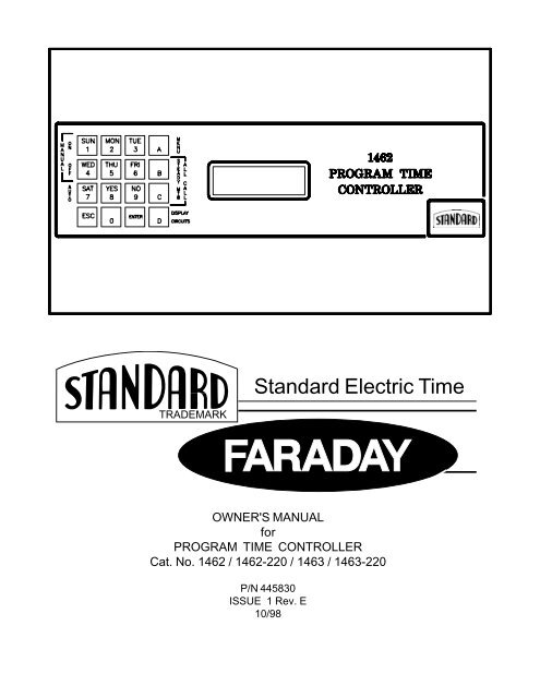
PROGRAM TIME CONTROLLER<br />
Cat. No. 1462 / 1462-220 / 1463 / 1463-220<br />
P/N 445830<br />
ISSUE 1 Rev. E<br />
10/98
1462/63 INSTRUCTION MANUAL<br />
IMPORTANT INSTALLATION AND WARRANTY INFORMATION<br />
WARRANTY INFORMATION: <strong>Faraday</strong>, LLC (the Manufacturer) provides a limited warranty to the Original Purchaser<br />
of this product. The Original Purchaser is the party to whom the Manufacturer issued its Sales Order, generally the<br />
Manufacturer's distributor. In order to preserve this warranty, it is important that the product be serviced only by<br />
persons who have been properly trained and authorized by the Manufacturer.<br />
Other parties involved in the installation of this product may have also provided a warranty which may be different<br />
than that of the manufacturer. The Manufacturer will only be responsible to the Original Purchaser and only for<br />
the Manufacturer's own warranty. For further information regarding the Manufacturer's warranty, contact the<br />
Original Purchaser.<br />
OWNER'S MANUAL: The owner's manual does not purport to cover all the details or variations in the equipment<br />
described, nor does it provide for every possible contingency to be met in connection with installation, operation<br />
and maintenance. All specifications subject to change without notice. Should further information be desired or<br />
should particular problems arise which are not covered sufficiently, the matter should be referred to the Installer<br />
or Original Purchaser listed below.<br />
INSTALLER INFORMATION<br />
COMPANY:_________________________________INSTALLER:___________________________PHONE:______________<br />
ADDRESS:__________________________________CITY:__________________STATE:___________ZIP:____________<br />
DATE INSTALLED:____________________________INSTALLER'S SIGNATURE:____________________<br />
ORIGINAL PURCHASER INFORMATION<br />
COMPANY:_________________________________________________________PHONE:____________________<br />
ADDRESS:__________________________________CITY:__________________STATE:___________ZIP:____________<br />
PURCHASER'S PURCHASE ORDER NO.:____________________________________________________<br />
DATE PURCHASED:______________________________________________________________________<br />
FARADAY SALES ORDER ACKNOWLEDGMENT NO.:__________________________________________<br />
ORIGINAL PURCHASER'S SIGNATURE:_____________________________________________________<br />
NOTE: A copy of the above completed information may be required by the manufacturer for authorization of<br />
Warranty services.<br />
Page 1
1462/63 INSTRUCTION MANUAL<br />
FCC FCC FCC COMPLIANCE<br />
COMPLIANCE<br />
WARNING: WARNING: This equipment generates, uses, and can radiate radio frequency energy and if<br />
not installed and used in accordance with this instruction manual, may cause interference to<br />
radio communications. It complies with the limits for a Class A computing device pursuant to<br />
Subpart J of Part 15 of FCC Rules, which are designed to provide reasonable protection<br />
against such interference when operated in a commercial environment. Operation of this<br />
equipment in a residential area is likely to cause interference in which case the user at his own<br />
expense will be required to take whatever measures may be required to correct the interference.<br />
ATTENTION<br />
OBSERVE PRECAUTIONS<br />
FOR HANDLING<br />
ELECTROSTATIC<br />
SENSITIVE<br />
DEVICES<br />
STATIC STATIC WARNING<br />
WARNING<br />
CAUTION: CAUTION: CAUTION: This equipment contains electronic devices that are sensitive to static electric<br />
charges. To guarantee protection for the circuitry of this unit, it is required that electrostatic<br />
handling precautions be observed when installing or repairing this equipment. Any technician<br />
or other personnel working on this unit must wear a static grounding wrist strap or similar device<br />
to provide protection of sensitive components.<br />
ELECTRIC ELECTRIC ELECTRIC SHOCK SHOCK HAZARD<br />
HAZARD<br />
WARNING:<br />
WARNING: Hazardous voltage in electrical equipment can cause severe personal injury or<br />
death. Inspection, installation, and preventive maintenance should only be performed on<br />
equipment to which power has been turned off, disconnected and electrically isolated so no<br />
accidental contact can be made with energized parts.<br />
Page 2
1462/63 INSTRUCTION MANUAL<br />
Table of Contents<br />
IMPORTANT INSTALLATION AND WARRANTY INFORMATION .................................................................. 1<br />
FCC COMPLIANCE .................................................................................................................... 2<br />
STATIC WARNING...................................................................................................................... 2<br />
ELECTRIC SHOCK HAZARD .......................................................................................................... 2<br />
TABLE OF CONTENTS ................................................................................................................ 3<br />
DESCRIPTION............................................................................................................................ 7<br />
GENERAL DESCRIPTION OF UNIT .............................................................................................. 7<br />
PROGRAM FEATURES ........................................................................................................... 7<br />
SYSTEM OPTIONS ................................................................................................................ 8<br />
SPECIFICATIONS ........................................................................................................................ 9<br />
INSTALLATION ......................................................................................................................... 10<br />
PARTS CHECKLIST ............................................................................................................. 10<br />
SURFACE MOUNT UNIT (1462, 1462-220) .......................................................................... 11<br />
PANEL MOUNTING ........................................................................................................ 11<br />
APPLYING POWER ........................................................................................................ 12<br />
ADJUSTING THE DISPLAY................................................................................................ 12<br />
CONNECTING FIELD DEVICES .......................................................................................... 13<br />
FINISHING THE INSTALLATION........................................................................................... 13<br />
LOCATION OF AC INPUT TERMINALS ON 1462 MAIN BOARD ................................................ 14<br />
WIRING A 1462 TO AC POWER ..................................................................................... 14<br />
EXPLODED VIEW OF 1462 CHASSIS ................................................................................ 15<br />
LOCATION OF JUMPERS ON CPU/DISPLAY BOARD OF THE 1462 .......................................... 15<br />
RACK MOUNT UNIT (1463, 1463-220) ................................................................................ 16<br />
PREPARING UNIT FOR EQUIPMENT RACK .......................................................................... 16<br />
GIVING UNIT A BENCH TEST .......................................................................................... 16<br />
ADJUSTING THE DISPLAY................................................................................................ 17<br />
INSTALLING THE UNIT INTO THE EQUIPMENT RACK .............................................................. 18<br />
CONNECTING FIELD DEVICES .......................................................................................... 19<br />
FINISHING THE INSTALLATION........................................................................................... 19<br />
LOCATION OF AC INPUT TERMINALS ON 1463 CHASSIS ...................................................... 20<br />
WIRING A 1463 TO AC POWER ..................................................................................... 20<br />
EXPLODED VIEW OF 1463 CHASSIS ................................................................................ 21<br />
LOCATION OF JUMPERS ON CPU BOARD OF THE 1463 ...................................................... 21<br />
OPERATION ............................................................................................................................ 22<br />
SYSTEM CONTROLS ........................................................................................................... 22<br />
HARDWARE RESET ....................................................................................................... 22<br />
KEYPAD ...................................................................................................................... 22<br />
DISPLAY ..................................................................................................................... 23<br />
USING THE SYSTEM CONTROLS TO OPERATE AND PROGRAM THE PROGRAM TIME CONTROLLER .23<br />
OPERATING THE PROGRAM TIME CONTROLLER ........................................................................ 25<br />
ACCESS CODE SECURITY .............................................................................................. 25<br />
DISPLAY CIRCUITS ........................................................................................................ 27<br />
FUNCTION KEYS ........................................................................................................... 27<br />
THE VIRTUAL ON/OFF/AUTO SWITCH .................................................................... 28<br />
MANUAL ON ..................................................................................................... 28<br />
MANUAL OFF .................................................................................................... 28<br />
AUTOMATIC ...................................................................................................... 29<br />
Page 3
1462/63 INSTRUCTION MANUAL<br />
Table of Contents<br />
ALL CALL .............................................................................................................. 29<br />
STEADY ALL CALL ............................................................................................. 29<br />
MTB ALL CALL ................................................................................................ 29<br />
PROGRAMMING THE PROGRAM TIME CONTROLLER .............................................................. 30<br />
LEVEL 1 PROGRAMMING ........................................................................................... 30<br />
SET SCHEDULE ................................................................................................. 30<br />
SET MAIN SCHEDULE.................................................................................... 30<br />
SET ALTERNATE SCHEDULE ........................................................................... 30<br />
LEVEL 2 PROGRAMMING ........................................................................................... 31<br />
PROGRAM EVENTS............................................................................................. 31<br />
WHAT IS AN EVENT AND WHY PROGRAM IT? .................................................... 31<br />
THE PROGRAM EVENTS / EDIT EVENTS MENU................................................... 32<br />
ADDING EVENTS .......................................................................................... 32<br />
SCANNING AND EDITING EVENTS ..................................................................... 33<br />
ALTERNATE DATES ............................................................................................ 36<br />
ADDING ALTERNATE DATES ............................................................................ 36<br />
SCANNING AND EDITING ALTERNATE DATES ...................................................... 37<br />
SET TIME......................................................................................................... 38<br />
SET DATE ........................................................................................................ 38<br />
MANUAL ADVANCE ............................................................................................. 39<br />
CLOCK ENABLE ................................................................................................. 39<br />
LEVEL 3 PROGRAMMING ........................................................................................... 40<br />
SET DEFAULTS.................................................................................................. 41<br />
SET TIME BASE ........................................................................................... 41<br />
TIME FORMAT.............................................................................................. 41<br />
SET LINE FREQ ........................................................................................... 42<br />
SET DAYLIGHT SAVINGS ................................................................................ 42<br />
ALL CALL FEATURE ...................................................................................... 42<br />
SERIAL PORT .............................................................................................. 42<br />
MASTER TO MASTER SYNC ............................................................................ 43<br />
PROGRAM CLOCKS ....................................................................................... 44<br />
FUNCTION KEYS........................................................................................... 44<br />
CLEAR MEMORY .......................................................................................... 45<br />
ACCESS CODE ................................................................................................... 45<br />
DIAGNOSTICS .................................................................................................... 46<br />
SPECIAL FUNCTIONS........................................................................................... 47<br />
TROUBLE SHOOTING GUIDE ...................................................................................................... 48<br />
TROUBLE SHOOTING GUIDELINES .......................................................................................... 48<br />
SECONDARY CLOCKS DON'T KEEP TIME ........................................................................... 48<br />
PROGRAM TIME CONTROLLER DOESN'T KEEP TIME ............................................................ 49<br />
BELL(S)/UTILITY DEVICE(S) WON'T OPERATE PROPERLY ........................................................... 49<br />
BELL(S)/UTILITY DEVICE(S) WON'T TURN OFF ........................................................................ 50<br />
Page 4
1462/63 INSTRUCTION MANUAL<br />
Table of Contents<br />
APPENDIX A: QUICK REFERENCE PROGRAMMING MENUS ........................................................... A-1<br />
PROGRAMMING MENU TABLE OF CONTENTS .......................................................................... A-1<br />
APPENDIX B: INSTALLATION OF SECONDARY CLOCKS ................................................................. B-1<br />
CLOCK CODE DESCRIPTIONS .............................................................................................. B-1<br />
CLOCK CODE TABLE ......................................................................................................... B-4<br />
FIG. 1 TYPICAL WIRING FOR SYNCHRONOUS CLOCK MOVEMENTS (SINGLE VOLTAGE) .......................... B-5<br />
FIG. 2 TYPICAL WIRING FOR SYNCHRONOUS CLOCK MOVEMENTS (DUAL VOLTAGE) ............................ B-6<br />
FIG. 3 TYPICAL WIRING FOR 2 WIRE POLARITY REVERSAL CLOCKS W/1415 CLOCK POWER SUPPLY<br />
AND 1416 CLOCK BOOSTER .............................................................................. B-7<br />
FIG. 4 TYPICAL WIRING FOR 2 WIRE POLARITY REVERSAL CLOCKS ......................................... B-8<br />
FIG. 5 TYPICAL WIRING FOR 2362 AND 2364 DIGITAL SECONDARY CLOCKS............................. B-9<br />
FIG. 6 TYPICAL WIRING FOR AR2 & AR2A CLOCKS .......................................................... B-10<br />
FIG. 7 TYPICAL WIRING FOR AR3 CLOCKS........................................................................ B-11<br />
FIG. 8 TYPICAL WIRING FOR 2 WIRE POLARITY REVERSAL IMPULSE CLOCKS (CLOCK CODE 21)......B-12<br />
FIG. 9 TYPICAL WIRING FOR 3 WIRE IMPULSE CLOCKS ........................................................ B-13<br />
FIG. 10 TYPICAL WIRING FOR 2 WIRE, MINUTE IMPULSE CLOCKS<br />
WITH NO HOURLY OR 12 HOUR CORRECTION ...................................................... B-14<br />
APPENDIX C: TYPICAL SIGNAL CIRCUIT WIRING ....................................................................... C-1<br />
FIG. A TYPICAL AUXILIARY CIRCUIT WIRING FOR SIGNAL DEVICES ........................................... C-1<br />
FIG. B TYPICAL AUXILIARY CIRCUIT WIRING FOR UTILITY CONTROL DEVICES ............................. C-2<br />
APPENDIX D: GLOSSARY OF TERMS ...................................................................................... D-1<br />
APPENDIX E: OPTION MODULE INSTALLATION INSTRUCTION SHEETS<br />
1464 FOUR BELL/AUXILIARY CIRCUIT ADDER OPTION INSTALLATION INSTRUCTIONS ........ P/N 445734<br />
1464R FOUR BELL/AUXILIARY CIRCUIT ADDER OPTION INSTALLATION INSTRUCTIONS ..... P/N 445735<br />
1466 MASTER-TO-MASTER SYNCHRONIZATION OPTION INSTALLATION INSTRUCTIONS ...... P/N 445739<br />
1468A RS-232 PORT OPTION INSTALLATION INSTRUCTIONS ..................................... P/N 445796<br />
APPENDIX F: PROGRAMMING SHEETS<br />
PROGRAM TIME CONTROLLER DEFAULT SETTINGS CHART<br />
PROGRAM TIME CONTROLLER - EVENTS CHART<br />
APPENDIX G: CODE CARD ................................................................................................... G-1<br />
Page 5
1462/63 INSTRUCTION MANUAL<br />
Page 6
I.) General Description of Unit:<br />
1462/63 INSTRUCTION MANUAL<br />
DESCRIPTION<br />
The 1462/1463 Program Time Controller is a microprocessor based <strong>time</strong> management unit. It<br />
provides synchronized control of most analog and digital secondary clock systems via its clock<br />
circuit.<br />
The 1462/1463 contains two <strong>program</strong>mable signal circuits. Each signal circuit provides automatic<br />
and manual control of signaling or utility devices. To increase the number of signal circuits to six,<br />
simply add the Four Bell/Auxiliary Circuit Adder Option.<br />
A sixteen key, multiple-function keypad allows the user to <strong>program</strong> the 1462/1463. It is also how<br />
the user performs manual clock advance, manual operation of the signal circuits, and all call. The<br />
abbreviated names for the keys provide a helpful reference for <strong>program</strong>ming the 1462/1463.<br />
A 16 character by 2 line LCD allows the user to monitor the 1462/1463’s status and response to<br />
<strong>program</strong>ming. Included is a backlight that either remains on continuously, or turns off after a short<br />
<strong>time</strong>, depending on the user’s requirements.<br />
Password security protects the system from unauthorized operation. Three levels of password<br />
security allow selective access to the 1462/1463’s features. The ability to enable or disable<br />
password security to some basic features, such as all call, provides even more flexibility.<br />
The 1462/1463’s <strong>time</strong> keeping synchronizes to either AC line frequency or a quartz controlled <strong>time</strong><br />
base. The <strong>time</strong> of day and date, as well as unit <strong>program</strong>ming, are stored in a non-volatile memory<br />
(NVRAM). The NVRAM saves this information in the event of a power failure.<br />
II.) Program Features:<br />
A.) NON-VOLATILE MEMORY (NVRAM) - The NVRAM stores all <strong>time</strong>, date, and <strong>program</strong>ming<br />
information. The NVRAM has an internal lithium battery. This pr<strong>events</strong> <strong>time</strong> keeping and data<br />
from being lost during AC power failures for up to ten years. The internal lithium battery<br />
requires no battery charging.<br />
B.) DAYLIGHT SAVINGS TIME - The 1462/1463 automatically changes the <strong>time</strong> of day for itself<br />
and the secondary clocks during a change to or from Daylight Savings Time. This feature can<br />
be “disabled” during <strong>program</strong>ming if not required.<br />
C.) LEAP YEAR - Event and calendar changes for leap year are done automatically.<br />
D.) ALTERNATE SCHEDULE - Any one of the available 10 schedules can be implemented on a<br />
per day basis for holidays, exam days, pep rallies, etc. The 1462/1463 will automatically return<br />
to the main schedule the next day.<br />
E.) ALTERNATE DATES - Up to 32 dates can be <strong>program</strong>med into the 1462/1463 in advance to<br />
automatically run alternate schedules for holidays, exam days, pep rallies, etc.The 1462/1463<br />
will automatically return to the main schedule the next day.<br />
Page 7
1462/63 INSTRUCTION MANUAL<br />
II.) Program Features (Cont'd)<br />
F.) EVENTS - The 1462 allows up to 300 <strong>events</strong> per day to be entered into memory. This is<br />
equivalent to 2100 possible <strong>events</strong> per week. Programmed <strong>events</strong> can be “start”, “stop”, or<br />
“duration” <strong>events</strong>. “Duration” <strong>events</strong> are normally used to operate signals. “Start” and “stop”<br />
<strong>events</strong> are usually used to turn utility devices on and off. Each “start” or “stop” event is<br />
considered a separate event.<br />
G.) DATE AND EVENT SCANNING - The alternate dates and <strong>events</strong> <strong>program</strong>med into the<br />
1462/1463 can be viewed and altered. The user can choose to scan all <strong>program</strong>med <strong>events</strong>,<br />
or just those connected with a certain schedule or signal circuit.<br />
III.) System Options:<br />
DESCRIPTION<br />
The standard 1462/1463 Program Time Controller can be enhanced by the following options:<br />
1464/1464R Four Bell/Auxiliary Circuit Adder Option expands the number of available signal<br />
circuits from two to six. With this option, all six signal circuits are independently <strong>program</strong>mable.<br />
1466 Master-to-Master Synchronization Option allows the 1462/1463 to synchronize or be<br />
synchronized by another device (usually another master clock).<br />
1468A RS-232 Port Option provides the 1462/1463 with an RS-232 serial port. The user can<br />
enable or disable this serial port, and select its baud rate. When enabled, once a minute it will<br />
transmit <strong>time</strong> and date to another RS-232 compatible device.<br />
Page 8
GENERAL<br />
1462/63 INSTRUCTION MANUAL<br />
SPECIFICATIONS<br />
Weight: 1462/1462-220 Program Time Controller: 6.9 lb<br />
1463/1463-220 Program Time Controller: 15.3 lb<br />
External Dimensions: 1462/1462-220 Program Time Controller: 12.000" X 7.250" X 3.875"<br />
1463/1463-220 Program Time Controller: 19.000" X 13.000" X 3.500"<br />
ELECTRICAL<br />
Power Requirements:<br />
Line Voltage: 1462/1463 Program Time Controller: 120 VAC 50/60 HZ 0.25 A<br />
1462-220/1463-220 Program Time Controller: 220 VAC 50/60 HZ 0.13 A<br />
Battery: Lithium Primary Battery<br />
(included)<br />
Input Power: 25 VA<br />
Memory Retention: 10 years<br />
ENVIRONMENTAL<br />
Normal Ambient Temperature for Operation: 25 C° (77 F°)<br />
OPERATION<br />
Clock Circuits:<br />
Number Available: 1 clock drive circuit<br />
Type: Form C<br />
Contact Ratings: Dry Contacts rated @<br />
3 A inductive<br />
(10 A resistive),<br />
28 VDC/120 VAC<br />
Surge protected and<br />
Fused @ 4 A<br />
Signal Circuits:<br />
Number Available: Standard: 2 signal circuits<br />
Maximum (with 1464/1464R): 6 signal circuits<br />
Type: Form A<br />
Contact Ratings: Dry Contacts rated @<br />
8 A inductive<br />
(30 A resistive),<br />
28 VDC/120 VAC<br />
Surge protected and unfused<br />
Number of Possible Schedules: 10 schedules<br />
Programmable Alternate Dates: 32 dates<br />
Programmable Events: per week: 2100 <strong>events</strong><br />
per day: 300 <strong>events</strong><br />
Time Base Accuracy:<br />
Line Frequency: line synchronous<br />
Oscillator: 200 ppm<br />
UL LISTED, File No. E-46264<br />
Page 9
1462/63 INSTRUCTION MANUAL<br />
WARNING:Installation to be done only by qualified<br />
personnel who read these installation<br />
instructions and understand them. Installation<br />
is to be done in accordance with the National<br />
Electrical Code and local electrical codes.<br />
I.) Parts Checklist<br />
INSTALLATION<br />
Parts Checklist for 1462 Program Time Controller<br />
Clock Assembly (complete surface mount Program Time Controller)<br />
Installation Kit<br />
(to include)<br />
Owner's Manual<br />
Screw, #6-32 x 1/2 Phillips Bnd Hd Machine Screw (qty 4)<br />
Flow<strong>chart</strong><br />
Envelope, Plastic<br />
Parts Checklist for 1463 Program Time Controller<br />
Panel Assembly (complete rack mount Program Time Controller)<br />
Installation Kit<br />
(to include)<br />
Owner's Manual<br />
Screw, #10-32 x 3/8 Truss Head Machine Screw (qty 4)<br />
Flow<strong>chart</strong><br />
Envelope, Plastic<br />
Screw, #6-32 x 1/2 Phillips Bnd Hd Machine Screw<br />
Screw, #10-32 x 3/8 Truss Head Machine<br />
Screw<br />
Page 10
II.) Surface Mount Unit (1462, 1462-220):<br />
A.) Panel Mounting:<br />
1462/63 INSTRUCTION MANUAL<br />
INSTALLATION<br />
1.) Prior to installing the 1462, ensure that all necessary parts are included in the carton. Check all<br />
items in the carton against the Parts Checklist.<br />
2.) Prepare the backplate for mounting.<br />
a.) Remove the four #6 X 3/8” sheet metal screws holding the front cover onto the backplate. Refer<br />
to diagram on page 15. Save these four sheet metal screws.<br />
b.) Carefully remove the front cover.<br />
c.) Locate the circuit board assemblies of the 1462. The main board is mounted to the backplate.<br />
The CPU/display board is mounted to the front cover. They are connected by a cable.<br />
d.) Disconnect the cable between the main board and the CPU/display board.<br />
e.) Remove the main board from the backplate. Save the six #6-32 X 1/4” machine screws that held<br />
the main board to the backplate.<br />
3.) Mount the backplate.<br />
a.) Locate the backplate on the wall at a height of approximately 4-1/2 feet from the floor. ENSURE<br />
THAT THE KNOCKOUTS ON THE BACK OF THE BACKPLATE ARE TO THE BOTTOM WHEN<br />
FACING THE BACKPLATE.<br />
b.) Four 3/16" holes are provided for securing the backplate to the wall. Use the #6- 32 X 1/2”<br />
screws provided in the installation kit when securing the backplate to a 2 gang box. Use the<br />
screws provided with the 4" square box when securing the backplate to a 4" square box.<br />
CAUTION: ELECTRIC SHOCK HAZARD! Ensure that NO electrical power is present on any wire<br />
before installation.<br />
4.) Pull all field wiring a minimum of 2 feet into the backplate through the knockouts. Knockouts are<br />
provided in the top, bottom, and back of the backplate.<br />
5.) Remove all metal shavings, dust, etc. from the backplate.<br />
6.) Remount the main board on the backplate using the six #6-32 X 1/4” machine screws saved from<br />
step II.A.2.e.<br />
NOTE: If an optional 1464, 1466, or 1468A module is to be added for the initial setup, installation should<br />
be done at this <strong>time</strong>. Refer to the Installation Instructions included with the module or<br />
Appendix E.<br />
CAUTION: ELECTRIC SHOCK HAZARD! Ensure that NO electrical power is present on any wire<br />
before installation.<br />
7.) Prepare field wiring for connection to the 1462.<br />
a.) Ensure that all field wiring is free of shorts and grounds.<br />
b.) Dress the wires for connection to the terminal blocks of the main board.<br />
i.) Ensure that no wire will be pinched or obstruct closure of the unit.<br />
ii.) Route field wiring away from sharp projections, corners, and internal components.<br />
NOTE: DO NOT CONNECT ANY WIRING AT THIS TIME.<br />
8.) Reconnect the cable disconnected in step II.A.2.d. The cable connects to main board J4 and<br />
CPU/display board J1.<br />
Page 11
B.) Applying Power:<br />
1462/63 INSTRUCTION MANUAL<br />
1.) Remove the protective cover on TB3 of the main board. Save the protective cover for<br />
step II.B.3.<br />
CAUTION: ELECTRIC SHOCK HAZARD! Ensure that NO electrical power is present on any wire<br />
before installation.<br />
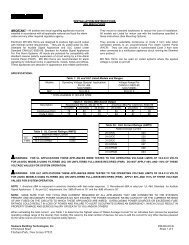
2.) Connect the AC power wires to the 1462. The wiring diagrams on page 14 show the proper connections<br />
to TB3 of the main board. Refer to the appropriate wiring diagram for your application.<br />
CAUTION: RISK OF ELECTRIC SHOCK! Chassis ground (“GND” terminal) MUST be<br />
connected to conduit/Earth ground to provide proper protection from electric shock.<br />
NOTE: Chassis ground (“GND” terminal) MUST be connected to conduit/Earth ground to provide proper<br />
protection of Program Time Controller circuitry.<br />
NOTE: Do not connect field devices at this <strong>time</strong>.<br />
3.) Replace the protective cover over TB3 of the main board.<br />
4.) Apply power to the 1462 by switching its circuit breaker on at the circuit breaker<br />
panel.<br />
a.) The 1462 should show the <strong>time</strong> and date (there may be as much as a 30 second delay after<br />
power up for the display to show <strong>time</strong> and date).<br />
b.) The LED on the main board (and on the 1464, if installed) blinks at a rate of about once per<br />
second.<br />
C.) Adjusting the Display:<br />
1.) Adjust the contrast of the display, if necessary.<br />
a.) Contrast affects the display’s readability. The following diagram will help you decide if the<br />
contrast of your display needs to be adjusted. IF CONTRAST OF THE DISPLAY IS ACCEPT-<br />
ABLE, SKIP THE REMAINDER OF STEP 1.<br />
GOOD<br />
CONTRAST<br />
TOO<br />
DARK<br />
INSTALLATION<br />
Good contrast- text is easy to read<br />
Contrast is too dark- text is difficult to read<br />
through the darkened background<br />
Contrast is too light- text is not dark enough to<br />
read<br />
b.) If the contrast needs to be adjusted, locate jumper W1 on the CPU/display board (see diagram<br />
on page 15). W1 sets the contrast for the display. If W1 is removed, the contrast becomes<br />
lighter. If W1 is installed, the contrast becomes darker.<br />
c.) Remove power to the 1462 by switching its circuit breaker off at the circuit breaker panel.<br />
d.) Adjust the contrast of the display.<br />
i.) If contrast is too dark, cut jumper W1 of the CPU/display board.<br />
ii.) If contrast is too light and jumper W1 of the CPU/display board is already cut, reinstall<br />
jumper W1.<br />
Page 12
1462/63 INSTRUCTION MANUAL<br />
INSTALLATION<br />
e.) Restore power to the 1462 by switching its circuit breaker on at the circuit breaker panel.<br />
i.) The 1462 should show the <strong>time</strong> and date.<br />
ii.) The LED on the main board (and on the 1464, if installed) blinks at a rate of about once per<br />
second.<br />
2.) Enable the display’s backlight <strong>time</strong>-out, if necessary.<br />
a.) Determine if the application requires the display’s backlight to turn off after 2 minutes. If not,<br />
SKIP THE REMAINDER OF STEP 2.<br />
The display is equipped with a backlight. The backlight makes the display easier to read, but<br />
causes the 1462 to draw slightly more current than if the backlight were not present. In most<br />
cases, the extra current consumption is not objectionable.<br />
b.) If the extra current consumption of having the backlight on continuously is objectionable, locate<br />
jumper W2 on the CPU/display board (see diagram on page 15). W2 is provided as a means to<br />
enable a <strong>time</strong>-out feature for the backlight. As long as W2 is installed, the display’s backlight<br />
will be on continuously. If W2 isremoved, the display’s backlight will be turned off most of the<br />
<strong>time</strong>. If someone operates the 1462, the display’s backlight will automatically turn on. When the<br />
user is finished operating the 1462, the display’s backlight automatically turns off about 2<br />
minutes later.<br />
c.) Remove power to the 1462 by switching its circuit breaker off at the circuit breaker panel.<br />
d.) Disable/enable the <strong>time</strong>-out feature of the display’s backlight as required.<br />
i.) To enable the <strong>time</strong>-out feature, cut jumper W2 of the CPU/display board.<br />
ii.) If you want the backlight to be on continuously and jumper W2 of the CPU/display board is<br />
already cut, re-install jumper W2.<br />
e.) Restore power to the 1462 by switching its circuit breaker on at the circuit breaker panel.<br />
i.) The 1462 should show the <strong>time</strong> and date.<br />
ii.) The LED on the main board (and on the 1464, if installed) blinks at a rate of about once per<br />
second.<br />
3.) Some applications demand a larger display than that of the 1462. For those applications, mount a<br />
secondary clock near the Program Time Controller.<br />
D.) Connecting Field Devices:<br />
CAUTION: ELECTRIC SHOCK HAZARD! Ensure that NO electrical power is present on any wire<br />
before installation.<br />
1.) Remove power to the 1462 by switching its circuit breaker off at the circuit breaker panel.<br />
2.) Connect appropriate field wiring to the clock circuit of the 1462. See Appendix B for clock circuit<br />
wiring diagrams.<br />
3.) Connect appropriate field wiring to the signal circuits of the 1462. See Appendix C for signal circuit<br />
wiring diagrams.<br />
4.) Restore power to the 1462 by switching its circuit breaker on at the circuit breaker panel.<br />
a.) The 1462 should show the <strong>time</strong> and date.<br />
b.) The LED on the main board (and on the 1464, if installed) blinks at a rate of about once per<br />
second.<br />
E.) Finishing the Installation:<br />
1.) Reattach the front cover of the 1462 to the backplate. Use the four #6 X 3/8” sheet metal screws<br />
removed in step II.A.2.a.<br />
2.) Fill out the “Installer Information” section on page 1 of this manual.<br />
Page 13
1462/63 INSTRUCTION MANUAL<br />
INSTALLATION<br />
Wiring AC Power to the 1462 Program Time Controller<br />
AC Input Terminals<br />
Location of AC Input Terminals on 1462 Main Board<br />
Page 14<br />
Line<br />
Neutral<br />
Conduit / Earth Ground<br />
Wiring a 1462 to 120VAC Power<br />
Line<br />
Neutral<br />
Conduit / Earth Ground<br />
Wiring a 1462-220 to 220VAC Power (Two Wire)<br />
Line1<br />
Neutral<br />
Line2<br />
Conduit / Earth Ground<br />
Wiring a 1462-220 to 220VAC Power (Three Wire)<br />
(Not connected)
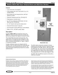
LOCATION OF W2 JUMPER<br />
1462/63 INSTRUCTION MANUAL<br />
INSTALLATION<br />
Screw, #6 x 3/8 Rec. Truss Hd. Type<br />
"A"<br />
EXPLODED VIEW OF THE 1462 CHASSIS<br />
LOCATION OF HARDWARE RESET PINS<br />
Page 15<br />
Back Plate<br />
Note Knockout Orientation<br />
LOCATION OF W1 JUMPER<br />
LOCATION OF JUMPERS ON CPU/DISPLAY BOARD OF THE 1462<br />
Cover<br />
Assembly
III.) Rack Mount Unit (1463, 1463-220):<br />
A.) Preparing the Equipment Rack:<br />
1462/63 INSTRUCTION MANUAL<br />
1.) Pull all field wiring into the 19" rack or console. Be sure to allow adequate wire length for connection<br />
to the external field terminals on the back of the 1463.<br />
CAUTION: ELECTRIC SHOCK HAZARD! Ensure that NO electrical power is present on any wire<br />
before installation.<br />
2.) Prepare field wiring for connection to the 1463.<br />
a.) Ensure that all field wiring is free of shorts and grounds.<br />
b.) Dress the wires for connection to the external field terminals on the back of the 1463.<br />
i.) Ensure that no wire will be pinched or obstruct installation of the 1463 into the equipment<br />
rack.<br />
ii.) Route field wiring away from sharp projections, corners, and internal components.<br />
NOTE: DO NOT CONNECT ANY WIRING AT THIS TIME.<br />
B.) Giving the Unit a Bench Test<br />
INSTALLATION<br />
1.) Prior to installing the 1463, ensure that all necessary parts are included in the carton. Check all<br />
items in the carton against the Parts Checklist.<br />
CAUTION: ELECTRIC SHOCK HAZARD! Ensure that ALL sources of electrical power are disconnected<br />
from the 1463 so that no accidental contact with energized parts can be made.<br />
CAUTION: STATIC SENSITIVE DEVICES! Be sure to wear a static grounding wrist strap or similar<br />
protective device when working inside of the 1463 chassis.<br />
NOTE: If an optional 1464R, 1466, or 1468A module is to be added for the initial setup, installation<br />
should be done at this <strong>time</strong>. Refer to the Installation Instructions included with the module or<br />
Appendix E.<br />
2.) Prepare the 1463 for a bench test.<br />
a.) Place the 1463 on a table or other work surface.<br />
b.) Remove the four #6 X 3/8" sheet metal screws holding the top cover onto the chassis. Refer to<br />
diagram on page 21. Save these four sheet metal screws.<br />
c.) Carefully remove the top cover.<br />
d.) Locate the circuit board assemblies of the 1463. The main board is mounted to the bottom of the<br />
chassis. The CPU and display boards are mounted to the front of the chassis.<br />
e.) Ensure that all cables inside the chassis are properly connected.<br />
i.) The six position cable is connected between J4 of the main board and J1 of the CPU board.<br />
ii.) The twenty-four position cable is connected between J2 of the CPU board and J1 of the<br />
display board.<br />
f.) Connect wiring between the terminals of the main board and external field terminals to satisfy<br />
your application. Refer to Appendices B and C for typical wiring diagrams for clock and signal<br />
circuits.<br />
Page 16
3.) Perform a bench test on the 1463:<br />
1462/63 INSTRUCTION MANUAL<br />
CAUTION: ELECTRIC SHOCK HAZARD! Ensure that ALL sources of electrical power are<br />
disconnected from the 1463 PRIOR TO performing adjustments and optional module<br />
installations so that no accidental contact with energized parts can be made.<br />
a.) Connect a temporary AC power source to the to the 1463. The temporary AC power source<br />
should be equipped with a switch capable of disconnecting AC power from the 1463. The wiring<br />
diagrams on page 20 show the proper connections to external AC power terminal block of the<br />
1463. Refer to the appropriate wiring diagram for your application.<br />
CAUTION: RISK OF ELECTRIC SHOCK! Chassis ground (“GND” terminal) MUST be connected to<br />
conduit/Earth ground to provide proper protection from electric shock.<br />
NOTE: Chassis ground (“GND” terminal) MUST be connected to conduit/Earth ground to provide proper<br />
protection of Program Time Controller circuitry.<br />
NOTE: Do not connect field devices at this <strong>time</strong>.<br />
b.) Apply power to the 1463 by switching on the temporary AC power source.<br />
i.) The 1463 should show the <strong>time</strong> and date (there may be as much as a 30 second delay after<br />
power up for the display to show <strong>time</strong> and date).<br />
ii.) The LED on the main board (and on the 1464R, if installed) blinks at a rate of about once per<br />
second.<br />
C.) Adjusting the Display<br />
1.) Adjust the contrast of the display, if necessary.<br />
a.) Contrast affects the display’s readability. The following diagram will help you decide if the<br />
contrast of your display needs to be adjusted. IF CONTRAST OF THE DISPLAY IS ACCEPT-<br />
ABLE, SKIP THE REMAINDER OF STEP 1.<br />
GOOD<br />
CONTRAST<br />
TOO<br />
DARK<br />
INSTALLATION<br />
Good contrast- text is easy to read<br />
Contrast is too dark- text is difficult to read<br />
through the darkened background<br />
Contrast is too light- text is not dark enough to<br />
read<br />
b.) If the contrast needs to be adjusted, locate jumper W1 on the CPU board (see diagram on page<br />
21). W1 sets the contrast for the display. If W1 is removed, the contrast becomes lighter. If W1<br />
is installed, the contrast becomes darker.<br />
c.) Remove power to the 1463 by switching its temporary AC power source off.<br />
d.) Adjust the contrast of the display.<br />
i.) If contrast is too dark, cut jumper W1 of the CPU board.<br />
ii.) If contrast is too light and jumper W1 of the CPU board is already cut, re-install jumper W1.<br />
e.) Restore power to the 1463 by switching its temporary AC power source on.<br />
i.) The 1463 should show the <strong>time</strong> and date.<br />
ii.) The LED on the main board (and on the 1464R, if installed) blinks at a rate of about once per<br />
second.<br />
Page 17
1462/63 INSTRUCTION MANUAL<br />
INSTALLATION<br />
2.) Enable the display’s backlight <strong>time</strong>-out, if necessary.<br />
a.) Determine if the application requires the display’s backlight to turn off after 2 minutes. If not,<br />
SKIP THE REMAINDER OF STEP 2.<br />
The display is equipped with a backlight. The backlight makes the display easier to read, but<br />
causes the 1463 to draw slightly more current than if the backlight were not present. In most<br />
cases, the extra current consumption is not objectionable.<br />
b.) If the extra current consumption of having the backlight on continuously is objectionable, locate<br />
jumper W2 on the CPU board (see diagram on page 21). W2 is provided as a means to enable<br />
a <strong>time</strong>-out feature for the backlight. As long as W2 is installed, the display’s backlight will be on<br />
continuously. If W2 is removed, the display’s backlight will be turned off most of the <strong>time</strong>. If<br />
someone operates the 1463, the display’s backlight will automatically turn on. When the user is<br />
finished operating the 1463, the display’s backlight automatically turns off about 2 minutes later.<br />
c.) Remove power to the 1463 by switching its temporary AC power source off.<br />
d.) Disable/enable the <strong>time</strong>-out feature of the display’s backlight as required.<br />
i.) To enable the <strong>time</strong>-out feature, cut jumper W2 of the CPU board.<br />
ii.) If you want the backlight to be on continuously and jumper W2 of the CPU board is already<br />
cut, re-install jumper W2.<br />
e.) Restore power to the 1463 by switching its temporary AC power source on.<br />
i.) The 1463 should show the <strong>time</strong> and date.<br />
ii.) The LED on the main board (and on the 1464R, if installed) blinks at a rate of about once per<br />
second.<br />
3.) Some applications demand a larger display than that of the 1463. For those applications, mount a<br />
secondary clock near the equipment rack the 1463 will be installed into.<br />
D.) Installing the Unit into the Equipment Rack:<br />
1.) Prepare the 1463 for installation into the equipment rack<br />
a.) Remove the temporary AC power source used to bench test the 1463.<br />
i.) Remove power to the 1463 by switching its temporary AC power source off.<br />
ii.) Remove the connections between the 1463 and the temporary AC power source.<br />
b.) Return the top cover of the 1463 onto the chassis. Use the four #6 X 3/8" sheet metal screws<br />
removed in step III.B.2.b. to secure the top cover to the chassis.<br />
CAUTION: ELECTRIC SHOCK HAZARD! Ensure that NO electrical power is present on any wire<br />
before installation.<br />
2.) Mount the 1463 into the equipment rack. Four slotted holes are provided on the front of the chassis.<br />
Use the #10-32 X 3/8" machine screws provided in the installation kit when securing the 1463 to the<br />
equipment rack.<br />
3.) Connect the AC power wires to the 1463. The wiring diagrams on page 20 show the proper connections<br />
to external AC power terminal block of the 1463. Refer to the appropriate wiring diagram for<br />
your application.<br />
CAUTION: RISK OF ELECTRIC SHOCK! Chassis ground (“GND” terminal) MUST be connected to<br />
conduit/Earth ground to provide proper protection from electric shock.<br />
NOTE: Chassis ground (“GND” terminal) MUST be connected to conduit/Earth ground to provide proper<br />
protection of Program Time Controller circuitry.<br />
NOTE: Do not connect field devices at this <strong>time</strong>.<br />
Page 18
1462/63 INSTRUCTION MANUAL<br />
4.) Apply power to the 1463 by switching its circuit breaker on at the circuit breaker panel. The 1463<br />
should show the <strong>time</strong> and date.<br />
E.) Connecting Field Devices:<br />
CAUTION: ELECTRIC SHOCK HAZARD! Ensure that NO electrical power is present on any wire<br />
before installation.<br />
1.) Remove power to the 1463 by switching its circuit breaker off at the circuit breaker panel.<br />
2.) Connect appropriate field wiring to the clock circuit of the 1463. See Appendix B for clock circuit<br />
wiring diagrams.<br />
3.) Connect appropriate field wiring to the signal circuits of the 1463. See Appendix C for signal circuit<br />
wiring diagrams.<br />
4.) Restore power to the 1463 by switching its circuit breaker on at the circuit breaker panel. The 1463<br />
should show the <strong>time</strong> and date.<br />
F.) Finishing the Installation:<br />
INSTALLATION<br />
1.) Fill out the “Installer Information” section on page 1 of this manual.<br />
Page 19
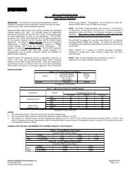
AC<br />
N<br />
GND<br />
1462/63 INSTRUCTION MANUAL<br />
INSTALLATION<br />
Wiring AC Power to the 1463 Program Time Controller<br />
Location of AC Input Terminals on 1463 Chassis<br />
Line<br />
Neutral<br />
Conduit / Earth Ground<br />
Wiring a 1463 to 120VAC Power<br />
Line<br />
Neutral<br />
Conduit / Earth Ground<br />
Wiring a 1463-220 to 220VAC Power (Two Wire)<br />
Line1<br />
Neutral<br />
Line2<br />
Conduit / Earth Ground<br />
Wiring a 1463-220 to 220VAC Power (Three Wire)<br />
Page 20<br />
AC Input Terminals<br />
AC Input Terminals<br />
(Not connected)
Cover<br />
1462/63 INSTRUCTION MANUAL<br />
Screw, #6-20 x 3/8<br />
Rec. Pan Hd.<br />
Type "AB"<br />
LOCATION OF W2 JUMPER<br />
INSTALLATION<br />
EXPLODED VIEW OF THE 1463 CHASSIS<br />
LOCATION OF HARDWARE RESET PINS<br />
LOCATION OF W1 JUMPER<br />
LOCATION OF JUMPERS ON CPU BOARD OF THE 1463<br />
Page 21<br />
1463<br />
Program Time<br />
Controller
1462/63 INSTRUCTION MANUAL<br />
IMPORTANT INSTALLATION AND WARRANTY INFORMATION<br />
WARRANTY INFORMATION: <strong>Faraday</strong>, LLC (the Manufacturer) provides a limited warranty to the Original Purchaser<br />
of this product. The Original Purchaser is the party to whom the Manufacturer issued its Sales Order, generally the<br />
Manufacturer's distributor. In order to preserve this warranty, it is important that the product be serviced only by<br />
persons who have been properly trained and authorized by the Manufacturer.<br />
Other parties involved in the installation of this product may have also provided a warranty which may be different<br />
than that of the manufacturer. The Manufacturer will only be responsible to the Original Purchaser and only for<br />
the Manufacturer's own warranty. For further information regarding the Manufacturer's warranty, contact the<br />
Original Purchaser.<br />
OWNER'S MANUAL: The owner's manual does not purport to cover all the details or variations in the equipment<br />
described, nor does it provide for every possible contingency to be met in connection with installation, operation<br />
and maintenance. All specifications subject to change without notice. Should further information be desired or<br />
should particular problems arise which are not covered sufficiently, the matter should be referred to the Installer<br />
or Original Purchaser listed below.<br />
INSTALLER INFORMATION<br />
COMPANY:_________________________________INSTALLER:___________________________PHONE:______________<br />
ADDRESS:__________________________________CITY:__________________STATE:___________ZIP:____________<br />
DATE INSTALLED:____________________________INSTALLER'S SIGNATURE:____________________<br />
ORIGINAL PURCHASER INFORMATION<br />
COMPANY:_________________________________________________________PHONE:____________________<br />
ADDRESS:__________________________________CITY:__________________STATE:___________ZIP:____________<br />
PURCHASER'S PURCHASE ORDER NO.:____________________________________________________<br />
DATE PURCHASED:______________________________________________________________________<br />
FARADAY SALES ORDER ACKNOWLEDGMENT NO.:__________________________________________<br />
ORIGINAL PURCHASER'S SIGNATURE:_____________________________________________________<br />
NOTE: A copy of the above completed information may be required by the manufacturer for authorization of<br />
Warranty services.<br />
Page 1
1462/63 INSTRUCTION MANUAL<br />
FCC FCC FCC COMPLIANCE<br />
COMPLIANCE<br />
WARNING: WARNING: This equipment generates, uses, and can radiate radio frequency energy and if<br />
not installed and used in accordance with this instruction manual, may cause interference to<br />
radio communications. It complies with the limits for a Class A computing device pursuant to<br />
Subpart J of Part 15 of FCC Rules, which are designed to provide reasonable protection<br />
against such interference when operated in a commercial environment. Operation of this<br />
equipment in a residential area is likely to cause interference in which case the user at his own<br />
expense will be required to take whatever measures may be required to correct the interference.<br />
ATTENTION<br />
OBSERVE PRECAUTIONS<br />
FOR HANDLING<br />
ELECTROSTATIC<br />
SENSITIVE<br />
DEVICES<br />
STATIC STATIC WARNING<br />
WARNING<br />
CAUTION: CAUTION: CAUTION: This equipment contains electronic devices that are sensitive to static electric<br />
charges. To guarantee protection for the circuitry of this unit, it is required that electrostatic<br />
handling precautions be observed when installing or repairing this equipment. Any technician<br />
or other personnel working on this unit must wear a static grounding wrist strap or similar device<br />
to provide protection of sensitive components.<br />
ELECTRIC ELECTRIC ELECTRIC SHOCK SHOCK HAZARD<br />
HAZARD<br />
WARNING:<br />
WARNING: Hazardous voltage in electrical equipment can cause severe personal injury or<br />
death. Inspection, installation, and preventive maintenance should only be performed on<br />
equipment to which power has been turned off, disconnected and electrically isolated so no<br />
accidental contact can be made with energized parts.<br />
Page 2
1462/63 INSTRUCTION MANUAL<br />
Table of Contents<br />
IMPORTANT INSTALLATION AND WARRANTY INFORMATION .................................................................. 1<br />
FCC COMPLIANCE .................................................................................................................... 2<br />
STATIC WARNING...................................................................................................................... 2<br />
ELECTRIC SHOCK HAZARD .......................................................................................................... 2<br />
TABLE OF CONTENTS ................................................................................................................ 3<br />
DESCRIPTION............................................................................................................................ 7<br />
GENERAL DESCRIPTION OF UNIT .............................................................................................. 7<br />
PROGRAM FEATURES ........................................................................................................... 7<br />
SYSTEM OPTIONS ................................................................................................................ 8<br />
SPECIFICATIONS ........................................................................................................................ 9<br />
INSTALLATION ......................................................................................................................... 10<br />
PARTS CHECKLIST ............................................................................................................. 10<br />
SURFACE MOUNT UNIT (1462, 1462-220) .......................................................................... 11<br />
PANEL MOUNTING ........................................................................................................ 11<br />
APPLYING POWER ........................................................................................................ 12<br />
ADJUSTING THE DISPLAY................................................................................................ 12<br />
CONNECTING FIELD DEVICES .......................................................................................... 13<br />
FINISHING THE INSTALLATION........................................................................................... 13<br />
LOCATION OF AC INPUT TERMINALS ON 1462 MAIN BOARD ................................................ 14<br />
WIRING A 1462 TO AC POWER ..................................................................................... 14<br />
EXPLODED VIEW OF 1462 CHASSIS ................................................................................ 15<br />
LOCATION OF JUMPERS ON CPU/DISPLAY BOARD OF THE 1462 .......................................... 15<br />
RACK MOUNT UNIT (1463, 1463-220) ................................................................................ 16<br />
PREPARING UNIT FOR EQUIPMENT RACK .......................................................................... 16<br />
GIVING UNIT A BENCH TEST .......................................................................................... 16<br />
ADJUSTING THE DISPLAY................................................................................................ 17<br />
INSTALLING THE UNIT INTO THE EQUIPMENT RACK .............................................................. 18<br />
CONNECTING FIELD DEVICES .......................................................................................... 19<br />
FINISHING THE INSTALLATION........................................................................................... 19<br />
LOCATION OF AC INPUT TERMINALS ON 1463 CHASSIS ...................................................... 20<br />
WIRING A 1463 TO AC POWER ..................................................................................... 20<br />
EXPLODED VIEW OF 1463 CHASSIS ................................................................................ 21<br />
LOCATION OF JUMPERS ON CPU BOARD OF THE 1463 ...................................................... 21<br />
OPERATION ............................................................................................................................ 22<br />
SYSTEM CONTROLS ........................................................................................................... 22<br />
HARDWARE RESET ....................................................................................................... 22<br />
KEYPAD ...................................................................................................................... 22<br />
DISPLAY ..................................................................................................................... 23<br />
USING THE SYSTEM CONTROLS TO OPERATE AND PROGRAM THE PROGRAM TIME CONTROLLER .23<br />
OPERATING THE PROGRAM TIME CONTROLLER ........................................................................ 25<br />
ACCESS CODE SECURITY .............................................................................................. 25<br />
DISPLAY CIRCUITS ........................................................................................................ 27<br />
FUNCTION KEYS ........................................................................................................... 27<br />
THE VIRTUAL ON/OFF/AUTO SWITCH .................................................................... 28<br />
MANUAL ON ..................................................................................................... 28<br />
MANUAL OFF .................................................................................................... 28<br />
AUTOMATIC ...................................................................................................... 29<br />
Page 3
1462/63 INSTRUCTION MANUAL<br />
Table of Contents<br />
ALL CALL .............................................................................................................. 29<br />
STEADY ALL CALL ............................................................................................. 29<br />
MTB ALL CALL ................................................................................................ 29<br />
PROGRAMMING THE PROGRAM TIME CONTROLLER .............................................................. 30<br />
LEVEL 1 PROGRAMMING ........................................................................................... 30<br />
SET SCHEDULE ................................................................................................. 30<br />
SET MAIN SCHEDULE.................................................................................... 30<br />
SET ALTERNATE SCHEDULE ........................................................................... 30<br />
LEVEL 2 PROGRAMMING ........................................................................................... 31<br />
PROGRAM EVENTS............................................................................................. 31<br />
WHAT IS AN EVENT AND WHY PROGRAM IT? .................................................... 31<br />
THE PROGRAM EVENTS / EDIT EVENTS MENU................................................... 32<br />
ADDING EVENTS .......................................................................................... 32<br />
SCANNING AND EDITING EVENTS ..................................................................... 33<br />
ALTERNATE DATES ............................................................................................ 36<br />
ADDING ALTERNATE DATES ............................................................................ 36<br />
SCANNING AND EDITING ALTERNATE DATES ...................................................... 37<br />
SET TIME......................................................................................................... 38<br />
SET DATE ........................................................................................................ 38<br />
MANUAL ADVANCE ............................................................................................. 39<br />
CLOCK ENABLE ................................................................................................. 39<br />
LEVEL 3 PROGRAMMING ........................................................................................... 40<br />
SET DEFAULTS.................................................................................................. 41<br />
SET TIME BASE ........................................................................................... 41<br />
TIME FORMAT.............................................................................................. 41<br />
SET LINE FREQ ........................................................................................... 42<br />
SET DAYLIGHT SAVINGS ................................................................................ 42<br />
ALL CALL FEATURE ...................................................................................... 42<br />
SERIAL PORT .............................................................................................. 42<br />
MASTER TO MASTER SYNC ............................................................................ 43<br />
PROGRAM CLOCKS ....................................................................................... 44<br />
FUNCTION KEYS........................................................................................... 44<br />
CLEAR MEMORY .......................................................................................... 45<br />
ACCESS CODE ................................................................................................... 45<br />
DIAGNOSTICS .................................................................................................... 46<br />
SPECIAL FUNCTIONS........................................................................................... 47<br />
TROUBLE SHOOTING GUIDE ...................................................................................................... 48<br />
TROUBLE SHOOTING GUIDELINES .......................................................................................... 48<br />
SECONDARY CLOCKS DON'T KEEP TIME ........................................................................... 48<br />
PROGRAM TIME CONTROLLER DOESN'T KEEP TIME ............................................................ 49<br />
BELL(S)/UTILITY DEVICE(S) WON'T OPERATE PROPERLY ........................................................... 49<br />
BELL(S)/UTILITY DEVICE(S) WON'T TURN OFF ........................................................................ 50<br />
Page 4
1462/63 INSTRUCTION MANUAL<br />
Table of Contents<br />
APPENDIX A: QUICK REFERENCE PROGRAMMING MENUS ........................................................... A-1<br />
PROGRAMMING MENU TABLE OF CONTENTS .......................................................................... A-1<br />
APPENDIX B: INSTALLATION OF SECONDARY CLOCKS ................................................................. B-1<br />
CLOCK CODE DESCRIPTIONS .............................................................................................. B-1<br />
CLOCK CODE TABLE ......................................................................................................... B-4<br />
FIG. 1 TYPICAL WIRING FOR SYNCHRONOUS CLOCK MOVEMENTS (SINGLE VOLTAGE) .......................... B-5<br />
FIG. 2 TYPICAL WIRING FOR SYNCHRONOUS CLOCK MOVEMENTS (DUAL VOLTAGE) ............................ B-6<br />
FIG. 3 TYPICAL WIRING FOR 2 WIRE POLARITY REVERSAL CLOCKS W/1415 CLOCK POWER SUPPLY<br />
AND 1416 CLOCK BOOSTER .............................................................................. B-7<br />
FIG. 4 TYPICAL WIRING FOR 2 WIRE POLARITY REVERSAL CLOCKS ......................................... B-8<br />
FIG. 5 TYPICAL WIRING FOR 2362 AND 2364 DIGITAL SECONDARY CLOCKS............................. B-9<br />
FIG. 6 TYPICAL WIRING FOR AR2 & AR2A CLOCKS .......................................................... B-10<br />
FIG. 7 TYPICAL WIRING FOR AR3 CLOCKS........................................................................ B-11<br />
FIG. 8 TYPICAL WIRING FOR 2 WIRE POLARITY REVERSAL IMPULSE CLOCKS (CLOCK CODE 21)......B-12<br />
FIG. 9 TYPICAL WIRING FOR 3 WIRE IMPULSE CLOCKS ........................................................ B-13<br />
FIG. 10 TYPICAL WIRING FOR 2 WIRE, MINUTE IMPULSE CLOCKS<br />
WITH NO HOURLY OR 12 HOUR CORRECTION ...................................................... B-14<br />
APPENDIX C: TYPICAL SIGNAL CIRCUIT WIRING ....................................................................... C-1<br />
FIG. A TYPICAL AUXILIARY CIRCUIT WIRING FOR SIGNAL DEVICES ........................................... C-1<br />
FIG. B TYPICAL AUXILIARY CIRCUIT WIRING FOR UTILITY CONTROL DEVICES ............................. C-2<br />
APPENDIX D: GLOSSARY OF TERMS ...................................................................................... D-1<br />
APPENDIX E: OPTION MODULE INSTALLATION INSTRUCTION SHEETS<br />
1464 FOUR BELL/AUXILIARY CIRCUIT ADDER OPTION INSTALLATION INSTRUCTIONS ........ P/N 445734<br />
1464R FOUR BELL/AUXILIARY CIRCUIT ADDER OPTION INSTALLATION INSTRUCTIONS ..... P/N 445735<br />
1466 MASTER-TO-MASTER SYNCHRONIZATION OPTION INSTALLATION INSTRUCTIONS ...... P/N 445739<br />
1468A RS-232 PORT OPTION INSTALLATION INSTRUCTIONS ..................................... P/N 445796<br />
APPENDIX F: PROGRAMMING SHEETS<br />
PROGRAM TIME CONTROLLER DEFAULT SETTINGS CHART<br />
PROGRAM TIME CONTROLLER - EVENTS CHART<br />
APPENDIX G: CODE CARD ................................................................................................... G-1<br />
Page 5
1462/63 INSTRUCTION MANUAL<br />
Page 6
I.) General Description of Unit:<br />
1462/63 INSTRUCTION MANUAL<br />
DESCRIPTION<br />
The 1462/1463 Program Time Controller is a microprocessor based <strong>time</strong> management unit. It<br />
provides synchronized control of most analog and digital secondary clock systems via its clock<br />
circuit.<br />
The 1462/1463 contains two <strong>program</strong>mable signal circuits. Each signal circuit provides automatic<br />
and manual control of signaling or utility devices. To increase the number of signal circuits to six,<br />
simply add the Four Bell/Auxiliary Circuit Adder Option.<br />
A sixteen key, multiple-function keypad allows the user to <strong>program</strong> the 1462/1463. It is also how<br />
the user performs manual clock advance, manual operation of the signal circuits, and all call. The<br />
abbreviated names for the keys provide a helpful reference for <strong>program</strong>ming the 1462/1463.<br />
A 16 character by 2 line LCD allows the user to monitor the 1462/1463’s status and response to<br />
<strong>program</strong>ming. Included is a backlight that either remains on continuously, or turns off after a short<br />
<strong>time</strong>, depending on the user’s requirements.<br />
Password security protects the system from unauthorized operation. Three levels of password<br />
security allow selective access to the 1462/1463’s features. The ability to enable or disable<br />
password security to some basic features, such as all call, provides even more flexibility.<br />
The 1462/1463’s <strong>time</strong> keeping synchronizes to either AC line frequency or a quartz controlled <strong>time</strong><br />
base. The <strong>time</strong> of day and date, as well as unit <strong>program</strong>ming, are stored in a non-volatile memory<br />
(NVRAM). The NVRAM saves this information in the event of a power failure.<br />
II.) Program Features:<br />
A.) NON-VOLATILE MEMORY (NVRAM) - The NVRAM stores all <strong>time</strong>, date, and <strong>program</strong>ming<br />
information. The NVRAM has an internal lithium battery. This pr<strong>events</strong> <strong>time</strong> keeping and data<br />
from being lost during AC power failures for up to ten years. The internal lithium battery<br />
requires no battery charging.<br />
B.) DAYLIGHT SAVINGS TIME - The 1462/1463 automatically changes the <strong>time</strong> of day for itself<br />
and the secondary clocks during a change to or from Daylight Savings Time. This feature can<br />
be “disabled” during <strong>program</strong>ming if not required.<br />
C.) LEAP YEAR - Event and calendar changes for leap year are done automatically.<br />
D.) ALTERNATE SCHEDULE - Any one of the available 10 schedules can be implemented on a<br />
per day basis for holidays, exam days, pep rallies, etc. The 1462/1463 will automatically return<br />
to the main schedule the next day.<br />
E.) ALTERNATE DATES - Up to 32 dates can be <strong>program</strong>med into the 1462/1463 in advance to<br />
automatically run alternate schedules for holidays, exam days, pep rallies, etc.The 1462/1463<br />
will automatically return to the main schedule the next day.<br />
Page 7
1462/63 INSTRUCTION MANUAL<br />
II.) Program Features (Cont'd)<br />
F.) EVENTS - The 1462 allows up to 300 <strong>events</strong> per day to be entered into memory. This is<br />
equivalent to 2100 possible <strong>events</strong> per week. Programmed <strong>events</strong> can be “start”, “stop”, or<br />
“duration” <strong>events</strong>. “Duration” <strong>events</strong> are normally used to operate signals. “Start” and “stop”<br />
<strong>events</strong> are usually used to turn utility devices on and off. Each “start” or “stop” event is<br />
considered a separate event.<br />
G.) DATE AND EVENT SCANNING - The alternate dates and <strong>events</strong> <strong>program</strong>med into the<br />
1462/1463 can be viewed and altered. The user can choose to scan all <strong>program</strong>med <strong>events</strong>,<br />
or just those connected with a certain schedule or signal circuit.<br />
III.) System Options:<br />
DESCRIPTION<br />
The standard 1462/1463 Program Time Controller can be enhanced by the following options:<br />
1464/1464R Four Bell/Auxiliary Circuit Adder Option expands the number of available signal<br />
circuits from two to six. With this option, all six signal circuits are independently <strong>program</strong>mable.<br />
1466 Master-to-Master Synchronization Option allows the 1462/1463 to synchronize or be<br />
synchronized by another device (usually another master clock).<br />
1468A RS-232 Port Option provides the 1462/1463 with an RS-232 serial port. The user can<br />
enable or disable this serial port, and select its baud rate. When enabled, once a minute it will<br />
transmit <strong>time</strong> and date to another RS-232 compatible device.<br />
Page 8
GENERAL<br />
1462/63 INSTRUCTION MANUAL<br />
SPECIFICATIONS<br />
Weight: 1462/1462-220 Program Time Controller: 6.9 lb<br />
1463/1463-220 Program Time Controller: 15.3 lb<br />
External Dimensions: 1462/1462-220 Program Time Controller: 12.000" X 7.250" X 3.875"<br />
1463/1463-220 Program Time Controller: 19.000" X 13.000" X 3.500"<br />
ELECTRICAL<br />
Power Requirements:<br />
Line Voltage: 1462/1463 Program Time Controller: 120 VAC 50/60 HZ 0.25 A<br />
1462-220/1463-220 Program Time Controller: 220 VAC 50/60 HZ 0.13 A<br />
Battery: Lithium Primary Battery<br />
(included)<br />
Input Power: 25 VA<br />
Memory Retention: 10 years<br />
ENVIRONMENTAL<br />
Normal Ambient Temperature for Operation: 25 C° (77 F°)<br />
OPERATION<br />
Clock Circuits:<br />
Number Available: 1 clock drive circuit<br />
Type: Form C<br />
Contact Ratings: Dry Contacts rated @<br />
3 A inductive<br />
(10 A resistive),<br />
28 VDC/120 VAC<br />
Surge protected and<br />
Fused @ 4 A<br />
Signal Circuits:<br />
Number Available: Standard: 2 signal circuits<br />
Maximum (with 1464/1464R): 6 signal circuits<br />
Type: Form A<br />
Contact Ratings: Dry Contacts rated @<br />
8 A inductive<br />
(30 A resistive),<br />
28 VDC/120 VAC<br />
Surge protected and unfused<br />
Number of Possible Schedules: 10 schedules<br />
Programmable Alternate Dates: 32 dates<br />
Programmable Events: per week: 2100 <strong>events</strong><br />
per day: 300 <strong>events</strong><br />
Time Base Accuracy:<br />
Line Frequency: line synchronous<br />
Oscillator: 200 ppm<br />
UL LISTED, File No. E-46264<br />
Page 9
1462/63 INSTRUCTION MANUAL<br />
WARNING:Installation to be done only by qualified<br />
personnel who read these installation<br />
instructions and understand them. Installation<br />
is to be done in accordance with the National<br />
Electrical Code and local electrical codes.<br />
I.) Parts Checklist<br />
INSTALLATION<br />
Parts Checklist for 1462 Program Time Controller<br />
Clock Assembly (complete surface mount Program Time Controller)<br />
Installation Kit<br />
(to include)<br />
Owner's Manual<br />
Screw, #6-32 x 1/2 Phillips Bnd Hd Machine Screw (qty 4)<br />
Flow<strong>chart</strong><br />
Envelope, Plastic<br />
Parts Checklist for 1463 Program Time Controller<br />
Panel Assembly (complete rack mount Program Time Controller)<br />
Installation Kit<br />
(to include)<br />
Owner's Manual<br />
Screw, #10-32 x 3/8 Truss Head Machine Screw (qty 4)<br />
Flow<strong>chart</strong><br />
Envelope, Plastic<br />
Screw, #6-32 x 1/2 Phillips Bnd Hd Machine Screw<br />
Screw, #10-32 x 3/8 Truss Head Machine<br />
Screw<br />
Page 10
II.) Surface Mount Unit (1462, 1462-220):<br />
A.) Panel Mounting:<br />
1462/63 INSTRUCTION MANUAL<br />
INSTALLATION<br />
1.) Prior to installing the 1462, ensure that all necessary parts are included in the carton. Check all<br />
items in the carton against the Parts Checklist.<br />
2.) Prepare the backplate for mounting.<br />
a.) Remove the four #6 X 3/8” sheet metal screws holding the front cover onto the backplate. Refer<br />
to diagram on page 15. Save these four sheet metal screws.<br />
b.) Carefully remove the front cover.<br />
c.) Locate the circuit board assemblies of the 1462. The main board is mounted to the backplate.<br />
The CPU/display board is mounted to the front cover. They are connected by a cable.<br />
d.) Disconnect the cable between the main board and the CPU/display board.<br />
e.) Remove the main board from the backplate. Save the six #6-32 X 1/4” machine screws that held<br />
the main board to the backplate.<br />
3.) Mount the backplate.<br />
a.) Locate the backplate on the wall at a height of approximately 4-1/2 feet from the floor. ENSURE<br />
THAT THE KNOCKOUTS ON THE BACK OF THE BACKPLATE ARE TO THE BOTTOM WHEN<br />
FACING THE BACKPLATE.<br />
b.) Four 3/16" holes are provided for securing the backplate to the wall. Use the #6- 32 X 1/2”<br />
screws provided in the installation kit when securing the backplate to a 2 gang box. Use the<br />
screws provided with the 4" square box when securing the backplate to a 4" square box.<br />
CAUTION: ELECTRIC SHOCK HAZARD! Ensure that NO electrical power is present on any wire<br />
before installation.<br />
4.) Pull all field wiring a minimum of 2 feet into the backplate through the knockouts. Knockouts are<br />
provided in the top, bottom, and back of the backplate.<br />
5.) Remove all metal shavings, dust, etc. from the backplate.<br />
6.) Remount the main board on the backplate using the six #6-32 X 1/4” machine screws saved from<br />
step II.A.2.e.<br />
NOTE: If an optional 1464, 1466, or 1468A module is to be added for the initial setup, installation should<br />
be done at this <strong>time</strong>. Refer to the Installation Instructions included with the module or<br />
Appendix E.<br />
CAUTION: ELECTRIC SHOCK HAZARD! Ensure that NO electrical power is present on any wire<br />
before installation.<br />
7.) Prepare field wiring for connection to the 1462.<br />
a.) Ensure that all field wiring is free of shorts and grounds.<br />
b.) Dress the wires for connection to the terminal blocks of the main board.<br />
i.) Ensure that no wire will be pinched or obstruct closure of the unit.<br />
ii.) Route field wiring away from sharp projections, corners, and internal components.<br />
NOTE: DO NOT CONNECT ANY WIRING AT THIS TIME.<br />
8.) Reconnect the cable disconnected in step II.A.2.d. The cable connects to main board J4 and<br />
CPU/display board J1.<br />
Page 11
B.) Applying Power:<br />
1462/63 INSTRUCTION MANUAL<br />
1.) Remove the protective cover on TB3 of the main board. Save the protective cover for<br />
step II.B.3.<br />
CAUTION: ELECTRIC SHOCK HAZARD! Ensure that NO electrical power is present on any wire<br />
before installation.<br />
2.) Connect the AC power wires to the 1462. The wiring diagrams on page 14 show the proper connections<br />
to TB3 of the main board. Refer to the appropriate wiring diagram for your application.<br />
CAUTION: RISK OF ELECTRIC SHOCK! Chassis ground (“GND” terminal) MUST be<br />
connected to conduit/Earth ground to provide proper protection from electric shock.<br />
NOTE: Chassis ground (“GND” terminal) MUST be connected to conduit/Earth ground to provide proper<br />
protection of Program Time Controller circuitry.<br />
NOTE: Do not connect field devices at this <strong>time</strong>.<br />
3.) Replace the protective cover over TB3 of the main board.<br />
4.) Apply power to the 1462 by switching its circuit breaker on at the circuit breaker<br />
panel.<br />
a.) The 1462 should show the <strong>time</strong> and date (there may be as much as a 30 second delay after<br />
power up for the display to show <strong>time</strong> and date).<br />
b.) The LED on the main board (and on the 1464, if installed) blinks at a rate of about once per<br />
second.<br />
C.) Adjusting the Display:<br />
1.) Adjust the contrast of the display, if necessary.<br />
a.) Contrast affects the display’s readability. The following diagram will help you decide if the<br />
contrast of your display needs to be adjusted. IF CONTRAST OF THE DISPLAY IS ACCEPT-<br />
ABLE, SKIP THE REMAINDER OF STEP 1.<br />
GOOD<br />
CONTRAST<br />
TOO<br />
DARK<br />
INSTALLATION<br />
Good contrast- text is easy to read<br />
Contrast is too dark- text is difficult to read<br />
through the darkened background<br />
Contrast is too light- text is not dark enough to<br />
read<br />
b.) If the contrast needs to be adjusted, locate jumper W1 on the CPU/display board (see diagram<br />
on page 15). W1 sets the contrast for the display. If W1 is removed, the contrast becomes<br />
lighter. If W1 is installed, the contrast becomes darker.<br />
c.) Remove power to the 1462 by switching its circuit breaker off at the circuit breaker panel.<br />
d.) Adjust the contrast of the display.<br />
i.) If contrast is too dark, cut jumper W1 of the CPU/display board.<br />
ii.) If contrast is too light and jumper W1 of the CPU/display board is already cut, reinstall<br />
jumper W1.<br />
Page 12
1462/63 INSTRUCTION MANUAL<br />
INSTALLATION<br />
e.) Restore power to the 1462 by switching its circuit breaker on at the circuit breaker panel.<br />
i.) The 1462 should show the <strong>time</strong> and date.<br />
ii.) The LED on the main board (and on the 1464, if installed) blinks at a rate of about once per<br />
second.<br />
2.) Enable the display’s backlight <strong>time</strong>-out, if necessary.<br />
a.) Determine if the application requires the display’s backlight to turn off after 2 minutes. If not,<br />
SKIP THE REMAINDER OF STEP 2.<br />
The display is equipped with a backlight. The backlight makes the display easier to read, but<br />
causes the 1462 to draw slightly more current than if the backlight were not present. In most<br />
cases, the extra current consumption is not objectionable.<br />
b.) If the extra current consumption of having the backlight on continuously is objectionable, locate<br />
jumper W2 on the CPU/display board (see diagram on page 15). W2 is provided as a means to<br />
enable a <strong>time</strong>-out feature for the backlight. As long as W2 is installed, the display’s backlight<br />
will be on continuously. If W2 isremoved, the display’s backlight will be turned off most of the<br />
<strong>time</strong>. If someone operates the 1462, the display’s backlight will automatically turn on. When the<br />
user is finished operating the 1462, the display’s backlight automatically turns off about 2<br />
minutes later.<br />
c.) Remove power to the 1462 by switching its circuit breaker off at the circuit breaker panel.<br />
d.) Disable/enable the <strong>time</strong>-out feature of the display’s backlight as required.<br />
i.) To enable the <strong>time</strong>-out feature, cut jumper W2 of the CPU/display board.<br />
ii.) If you want the backlight to be on continuously and jumper W2 of the CPU/display board is<br />
already cut, re-install jumper W2.<br />
e.) Restore power to the 1462 by switching its circuit breaker on at the circuit breaker panel.<br />
i.) The 1462 should show the <strong>time</strong> and date.<br />
ii.) The LED on the main board (and on the 1464, if installed) blinks at a rate of about once per<br />
second.<br />
3.) Some applications demand a larger display than that of the 1462. For those applications, mount a<br />
secondary clock near the Program Time Controller.<br />
D.) Connecting Field Devices:<br />
CAUTION: ELECTRIC SHOCK HAZARD! Ensure that NO electrical power is present on any wire<br />
before installation.<br />
1.) Remove power to the 1462 by switching its circuit breaker off at the circuit breaker panel.<br />
2.) Connect appropriate field wiring to the clock circuit of the 1462. See Appendix B for clock circuit<br />
wiring diagrams.<br />
3.) Connect appropriate field wiring to the signal circuits of the 1462. See Appendix C for signal circuit<br />
wiring diagrams.<br />
4.) Restore power to the 1462 by switching its circuit breaker on at the circuit breaker panel.<br />
a.) The 1462 should show the <strong>time</strong> and date.<br />
b.) The LED on the main board (and on the 1464, if installed) blinks at a rate of about once per<br />
second.<br />
E.) Finishing the Installation:<br />
1.) Reattach the front cover of the 1462 to the backplate. Use the four #6 X 3/8” sheet metal screws<br />
removed in step II.A.2.a.<br />
2.) Fill out the “Installer Information” section on page 1 of this manual.<br />
Page 13
1462/63 INSTRUCTION MANUAL<br />
INSTALLATION<br />
Wiring AC Power to the 1462 Program Time Controller<br />
AC Input Terminals<br />
Location of AC Input Terminals on 1462 Main Board<br />
Page 14<br />
Line<br />
Neutral<br />
Conduit / Earth Ground<br />
Wiring a 1462 to 120VAC Power<br />
Line<br />
Neutral<br />
Conduit / Earth Ground<br />
Wiring a 1462-220 to 220VAC Power (Two Wire)<br />
Line1<br />
Neutral<br />
Line2<br />
Conduit / Earth Ground<br />
Wiring a 1462-220 to 220VAC Power (Three Wire)<br />
(Not connected)
LOCATION OF W2 JUMPER<br />
1462/63 INSTRUCTION MANUAL<br />
INSTALLATION<br />
Screw, #6 x 3/8 Rec. Truss Hd. Type<br />
"A"<br />
EXPLODED VIEW OF THE 1462 CHASSIS<br />
LOCATION OF HARDWARE RESET PINS<br />
Page 15<br />
Back Plate<br />
Note Knockout Orientation<br />
LOCATION OF W1 JUMPER<br />
LOCATION OF JUMPERS ON CPU/DISPLAY BOARD OF THE 1462<br />
Cover<br />
Assembly
III.) Rack Mount Unit (1463, 1463-220):<br />
A.) Preparing the Equipment Rack:<br />
1462/63 INSTRUCTION MANUAL<br />
1.) Pull all field wiring into the 19" rack or console. Be sure to allow adequate wire length for connection<br />
to the external field terminals on the back of the 1463.<br />
CAUTION: ELECTRIC SHOCK HAZARD! Ensure that NO electrical power is present on any wire<br />
before installation.<br />
2.) Prepare field wiring for connection to the 1463.<br />
a.) Ensure that all field wiring is free of shorts and grounds.<br />
b.) Dress the wires for connection to the external field terminals on the back of the 1463.<br />
i.) Ensure that no wire will be pinched or obstruct installation of the 1463 into the equipment<br />
rack.<br />
ii.) Route field wiring away from sharp projections, corners, and internal components.<br />
NOTE: DO NOT CONNECT ANY WIRING AT THIS TIME.<br />
B.) Giving the Unit a Bench Test<br />
INSTALLATION<br />
1.) Prior to installing the 1463, ensure that all necessary parts are included in the carton. Check all<br />
items in the carton against the Parts Checklist.<br />
CAUTION: ELECTRIC SHOCK HAZARD! Ensure that ALL sources of electrical power are disconnected<br />
from the 1463 so that no accidental contact with energized parts can be made.<br />
CAUTION: STATIC SENSITIVE DEVICES! Be sure to wear a static grounding wrist strap or similar<br />
protective device when working inside of the 1463 chassis.<br />
NOTE: If an optional 1464R, 1466, or 1468A module is to be added for the initial setup, installation<br />
should be done at this <strong>time</strong>. Refer to the Installation Instructions included with the module or<br />
Appendix E.<br />
2.) Prepare the 1463 for a bench test.<br />
a.) Place the 1463 on a table or other work surface.<br />
b.) Remove the four #6 X 3/8" sheet metal screws holding the top cover onto the chassis. Refer to<br />
diagram on page 21. Save these four sheet metal screws.<br />
c.) Carefully remove the top cover.<br />
d.) Locate the circuit board assemblies of the 1463. The main board is mounted to the bottom of the<br />
chassis. The CPU and display boards are mounted to the front of the chassis.<br />
e.) Ensure that all cables inside the chassis are properly connected.<br />
i.) The six position cable is connected between J4 of the main board and J1 of the CPU board.<br />
ii.) The twenty-four position cable is connected between J2 of the CPU board and J1 of the<br />
display board.<br />
f.) Connect wiring between the terminals of the main board and external field terminals to satisfy<br />
your application. Refer to Appendices B and C for typical wiring diagrams for clock and signal<br />
circuits.<br />
Page 16
3.) Perform a bench test on the 1463:<br />
1462/63 INSTRUCTION MANUAL<br />
CAUTION: ELECTRIC SHOCK HAZARD! Ensure that ALL sources of electrical power are<br />
disconnected from the 1463 PRIOR TO performing adjustments and optional module<br />
installations so that no accidental contact with energized parts can be made.<br />
a.) Connect a temporary AC power source to the to the 1463. The temporary AC power source<br />
should be equipped with a switch capable of disconnecting AC power from the 1463. The wiring<br />
diagrams on page 20 show the proper connections to external AC power terminal block of the<br />
1463. Refer to the appropriate wiring diagram for your application.<br />
CAUTION: RISK OF ELECTRIC SHOCK! Chassis ground (“GND” terminal) MUST be connected to<br />
conduit/Earth ground to provide proper protection from electric shock.<br />
NOTE: Chassis ground (“GND” terminal) MUST be connected to conduit/Earth ground to provide proper<br />
protection of Program Time Controller circuitry.<br />
NOTE: Do not connect field devices at this <strong>time</strong>.<br />
b.) Apply power to the 1463 by switching on the temporary AC power source.<br />
i.) The 1463 should show the <strong>time</strong> and date (there may be as much as a 30 second delay after<br />
power up for the display to show <strong>time</strong> and date).<br />
ii.) The LED on the main board (and on the 1464R, if installed) blinks at a rate of about once per<br />
second.<br />
C.) Adjusting the Display<br />
1.) Adjust the contrast of the display, if necessary.<br />
a.) Contrast affects the display’s readability. The following diagram will help you decide if the<br />
contrast of your display needs to be adjusted. IF CONTRAST OF THE DISPLAY IS ACCEPT-<br />
ABLE, SKIP THE REMAINDER OF STEP 1.<br />
GOOD<br />
CONTRAST<br />
TOO<br />
DARK<br />
INSTALLATION<br />
Good contrast- text is easy to read<br />
Contrast is too dark- text is difficult to read<br />
through the darkened background<br />
Contrast is too light- text is not dark enough to<br />
read<br />
b.) If the contrast needs to be adjusted, locate jumper W1 on the CPU board (see diagram on page<br />
21). W1 sets the contrast for the display. If W1 is removed, the contrast becomes lighter. If W1<br />
is installed, the contrast becomes darker.<br />
c.) Remove power to the 1463 by switching its temporary AC power source off.<br />
d.) Adjust the contrast of the display.<br />
i.) If contrast is too dark, cut jumper W1 of the CPU board.<br />
ii.) If contrast is too light and jumper W1 of the CPU board is already cut, re-install jumper W1.<br />
e.) Restore power to the 1463 by switching its temporary AC power source on.<br />
i.) The 1463 should show the <strong>time</strong> and date.<br />
ii.) The LED on the main board (and on the 1464R, if installed) blinks at a rate of about once per<br />
second.<br />
Page 17
1462/63 INSTRUCTION MANUAL<br />
INSTALLATION<br />
2.) Enable the display’s backlight <strong>time</strong>-out, if necessary.<br />
a.) Determine if the application requires the display’s backlight to turn off after 2 minutes. If not,<br />
SKIP THE REMAINDER OF STEP 2.<br />
The display is equipped with a backlight. The backlight makes the display easier to read, but<br />
causes the 1463 to draw slightly more current than if the backlight were not present. In most<br />
cases, the extra current consumption is not objectionable.<br />
b.) If the extra current consumption of having the backlight on continuously is objectionable, locate<br />
jumper W2 on the CPU board (see diagram on page 21). W2 is provided as a means to enable<br />
a <strong>time</strong>-out feature for the backlight. As long as W2 is installed, the display’s backlight will be on<br />
continuously. If W2 is removed, the display’s backlight will be turned off most of the <strong>time</strong>. If<br />
someone operates the 1463, the display’s backlight will automatically turn on. When the user is<br />
finished operating the 1463, the display’s backlight automatically turns off about 2 minutes later.<br />
c.) Remove power to the 1463 by switching its temporary AC power source off.<br />
d.) Disable/enable the <strong>time</strong>-out feature of the display’s backlight as required.<br />
i.) To enable the <strong>time</strong>-out feature, cut jumper W2 of the CPU board.<br />
ii.) If you want the backlight to be on continuously and jumper W2 of the CPU board is already<br />
cut, re-install jumper W2.<br />
e.) Restore power to the 1463 by switching its temporary AC power source on.<br />
i.) The 1463 should show the <strong>time</strong> and date.<br />
ii.) The LED on the main board (and on the 1464R, if installed) blinks at a rate of about once per<br />
second.<br />
3.) Some applications demand a larger display than that of the 1463. For those applications, mount a<br />
secondary clock near the equipment rack the 1463 will be installed into.<br />
D.) Installing the Unit into the Equipment Rack:<br />
1.) Prepare the 1463 for installation into the equipment rack<br />
a.) Remove the temporary AC power source used to bench test the 1463.<br />
i.) Remove power to the 1463 by switching its temporary AC power source off.<br />
ii.) Remove the connections between the 1463 and the temporary AC power source.<br />
b.) Return the top cover of the 1463 onto the chassis. Use the four #6 X 3/8" sheet metal screws<br />
removed in step III.B.2.b. to secure the top cover to the chassis.<br />
CAUTION: ELECTRIC SHOCK HAZARD! Ensure that NO electrical power is present on any wire<br />
before installation.<br />
2.) Mount the 1463 into the equipment rack. Four slotted holes are provided on the front of the chassis.<br />
Use the #10-32 X 3/8" machine screws provided in the installation kit when securing the 1463 to the<br />
equipment rack.<br />
3.) Connect the AC power wires to the 1463. The wiring diagrams on page 20 show the proper connections<br />
to external AC power terminal block of the 1463. Refer to the appropriate wiring diagram for<br />
your application.<br />
CAUTION: RISK OF ELECTRIC SHOCK! Chassis ground (“GND” terminal) MUST be connected to<br />
conduit/Earth ground to provide proper protection from electric shock.<br />
NOTE: Chassis ground (“GND” terminal) MUST be connected to conduit/Earth ground to provide proper<br />
protection of Program Time Controller circuitry.<br />
NOTE: Do not connect field devices at this <strong>time</strong>.<br />
Page 18
1462/63 INSTRUCTION MANUAL<br />
4.) Apply power to the 1463 by switching its circuit breaker on at the circuit breaker panel. The 1463<br />
should show the <strong>time</strong> and date.<br />
E.) Connecting Field Devices:<br />
CAUTION: ELECTRIC SHOCK HAZARD! Ensure that NO electrical power is present on any wire<br />
before installation.<br />
1.) Remove power to the 1463 by switching its circuit breaker off at the circuit breaker panel.<br />
2.) Connect appropriate field wiring to the clock circuit of the 1463. See Appendix B for clock circuit<br />
wiring diagrams.<br />
3.) Connect appropriate field wiring to the signal circuits of the 1463. See Appendix C for signal circuit<br />
wiring diagrams.<br />
4.) Restore power to the 1463 by switching its circuit breaker on at the circuit breaker panel. The 1463<br />
should show the <strong>time</strong> and date.<br />
F.) Finishing the Installation:<br />
INSTALLATION<br />
1.) Fill out the “Installer Information” section on page 1 of this manual.<br />
Page 19
AC<br />
N<br />
GND<br />
1462/63 INSTRUCTION MANUAL<br />
INSTALLATION<br />
Wiring AC Power to the 1463 Program Time Controller<br />
Location of AC Input Terminals on 1463 Chassis<br />
Line<br />
Neutral<br />
Conduit / Earth Ground<br />
Wiring a 1463 to 120VAC Power<br />
Line<br />
Neutral<br />
Conduit / Earth Ground<br />
Wiring a 1463-220 to 220VAC Power (Two Wire)<br />
Line1<br />
Neutral<br />
Line2<br />
Conduit / Earth Ground<br />
Wiring a 1463-220 to 220VAC Power (Three Wire)<br />
Page 20<br />
AC Input Terminals<br />
AC Input Terminals<br />
(Not connected)
Cover<br />
1462/63 INSTRUCTION MANUAL<br />
Screw, #6-20 x 3/8<br />
Rec. Pan Hd.<br />
Type "AB"<br />
LOCATION OF W2 JUMPER<br />
INSTALLATION<br />
EXPLODED VIEW OF THE 1463 CHASSIS<br />
LOCATION OF HARDWARE RESET PINS<br />
LOCATION OF W1 JUMPER<br />
LOCATION OF JUMPERS ON CPU BOARD OF THE 1463<br />
Page 21<br />
1463<br />
Program Time<br />
Controller
I.) System Controls<br />
1462/63 1462/63 1462/63 INSTRUCTION INSTRUCTION MANUAL<br />
MANUAL<br />
OPERATION<br />
OPERATION<br />
There are three mechanisms an operator can use to operate and <strong>program</strong> a 1462/1463<br />
Program Time Controller. These mechanisms are: (1) the hardware reset; (2) the keypad;<br />
and (3) the display.<br />
A.) Hardware Reset<br />
The hardware reset is least often used of the three system controls. The hardware<br />
reset is a two pin header found on the CPU/display board of the 1462 or the CPU board<br />
of the 1463. Refer to the appropriate diagram on page 15 or 21 to locate the hardware<br />
reset of your unit.<br />
The hardware reset is an input to the microprocessor of the Program Time Controller.<br />
When used, the Program Time Controller restarts its operating software. This has the<br />
same effect as removing, and then restoring, the AC power of the Program Time Controller.<br />
The software routine running at the <strong>time</strong> of reset ceases, but the data (<strong>program</strong>ming<br />
and configuration information) already stored in the NVRAM remains intact.<br />
WARNING: ELECTRIC SHOCK HAZARD! Hazardous voltage in electrical equipment<br />
can cause severe personal injury or death. When performing a hardware<br />
reset, be careful not to touch the metallic object to anything other than the<br />
hardware reset header.<br />
To perform a hardware reset, you must have access to the CPU/display board (for a<br />
1462) or CPU board (for a 1463). While the Program Time Controller has AC power<br />
applied to it, carefully short for a moment the two pins of the header with a metallic<br />
object, such as a screwdriver. When the hardware reset is completed, the display will<br />
show the <strong>time</strong> and date.<br />
B.) Keypad<br />
The Program Time Controller has a sixteen key, multiple function keypad. This keypad<br />
is the operator’s means of “talking” to the Program Time Controller. It is how the operator<br />
uses and <strong>program</strong>s the Program Time Controller. The operator also uses it to answer<br />
questions, called prompts, asked by the Program Time Controller. The keypad is<br />
multiple function because many of its keys are used for more than one purpose.<br />
The ‘Enter’ ‘Enter’ ‘Enter’ ‘Enter’ ‘Enter’ and ‘Esc’ ‘Esc’ ‘Esc’ ‘Esc’ ‘Esc’ keys are the only two keys of the keypad that have a dedicated<br />
function. The ‘Enter’ ‘Enter’ ‘Enter’ ‘Enter’ ‘Enter’ key is used to actually send some information to the Program<br />
Time Controller’s memory. The ‘Esc’ ‘Esc’ ‘Esc’ ‘Esc’ ‘Esc’ key is used to back out of any procedure the<br />
operator is performing. From almost any routine the Program Time Controller is running,<br />
repeatedly pressing the ‘Esc’ ‘Esc’ ‘Esc’ ‘Esc’ ‘Esc’ key enough <strong>time</strong>s will allow the operator to get back<br />
to the date and <strong>time</strong> display without changing the data stored in memory.<br />
The ‘0’ ‘0’ ‘0’ ‘0’ ‘0’ to ‘9’ ‘9’ ‘9’ ‘9’ ‘9’ keys and ‘A’ ‘A’ ‘A’ ‘A’ ‘A’ to ‘D’ ‘D’ ‘D’ ‘D’ ‘D’ keys are used to answer most prompts on the display.<br />
These keys are most often used to choose a menu item or select a signal circuit for<br />
<strong>program</strong>ming.<br />
The ‘SUN’ ‘SUN’ ‘SUN’ ‘SUN’ ‘SUN’ to ‘SA ‘SA ‘SAT’ ‘SA ‘SAT’<br />
T’ T’ T’ keys are the same as the ‘1’ ‘1’ ‘1’ ‘1’ ‘1’ to ‘7’ ‘7’ ‘7’ ‘7’ ‘7’ keys, respectively. These keys<br />
refer to days of the week when answering prompts for days of the week.<br />
The ‘YES’ ‘YES’ ‘YES’ ‘YES’ ‘YES’ and ‘NO’ ‘NO’ ‘NO’ ‘NO’ ‘NO’ keys are the same as the ‘8’ ‘8’ ‘8’ ‘8’ ‘8’ and ‘9’ ‘9’ ‘9’ ‘9’ ‘9’ keys, respectively. These<br />
keys are used to answer prompts requiring a response of “yes” or “no.”<br />
Page 22
1462/63 1462/63 INSTRUCTION INSTRUCTION MANUAL<br />
MANUAL<br />
OPERATION<br />
OPERATION<br />
The ‘Display ‘Display ‘Display ‘Display ‘Display Clock Clock Clock Clock Clock Circuit’ Circuit’ Circuit’ Circuit’ Circuit’ and ‘Display ‘Display ‘Display ‘Display ‘Display Signal Signal Signal Signal Signal Circuits’ Circuits’ Circuits’ Circuits’ Circuits’ keys are the same as the<br />
‘0’ ‘0’ ‘0’ ‘0’ ‘0’ and the ‘D’ ‘D’ ‘D’ ‘D’ ‘D’ keys, respectively. Operating these keys for these functions is described<br />
later in this section of this manual.<br />
The ‘Man ‘Man ‘Manual ‘Man ‘Manual<br />
ual ual ual On’, On’ On’ On’ On’ ‘Man ‘Man ‘Manual ‘Man ‘Manual<br />
ual ual ual Off’’’’’, Off Off Off Off and ‘A ‘A ‘Auto’ ‘A ‘Auto’<br />
uto’ uto’ uto’ keys are the same as the ‘1’, ‘1’ ‘1’ ‘1’ ‘1’ ‘4’, ‘4’ ‘4’ ‘4’ ‘4’ and ‘7’ ‘7’ ‘7’ ‘7’ ‘7’<br />
keys, respectively. The ‘Stead ‘Stead ‘Steady ‘Stead ‘Steady<br />
y y y All All All All All Call’, Call’ Call’ Call’ Call’ and ‘MTB ‘MTB ‘MTB ‘MTB ‘MTB All All All All All Call’ Call’ Call’ Call’ Call’ keys are the same as the<br />
‘B’ ‘B’ ‘B’ ‘B’ ‘B’ and the ‘C’ ‘C’ ‘C’ ‘C’ ‘C’ keys, respectively. When functioning in this capacity, these keys are<br />
known as Function Keys. Operation of Function Keys is described later in this section<br />
of this manual.<br />
The ‘Men ‘Men ‘Menu’ ‘Men ‘Menu’<br />
u’ u’ u’ key is the same as the ‘A’ ‘A’ ‘A’ ‘A’ ‘A’ key. Operation of this key is described later in<br />
this section of this manual.<br />
All of the keys are used in conjunction with the display to allow the operator to interface<br />
with the Program Time Controller.<br />
C.) Display<br />
The display of the Program Time Controller is a 16 character by 2 line LCD. This<br />
display normally displays <strong>time</strong> of day, date, and schedule that is currently running. The<br />
display of that information is commonly referred to as the “<strong>time</strong> and date display.”<br />
Mon 10:58:21 AM<br />
3-27-95 1<br />
Page 23<br />
Current Schedule<br />
The display is also used in conjunction with the keypad to allow the operator to interface<br />
with the Program Time Controller. When the operator is using the Program Time<br />
Controller, the display provides information to help the operator.<br />
The display is equipped with a backlight. This backlight is factory <strong>program</strong>med to<br />
remain on continuously. It is possible to field <strong>program</strong> the backlight to be off most of<br />
the <strong>time</strong>. If field <strong>program</strong>med this way, the backlight would automatically turn on if the<br />
keypad of the Program Time Controller is used, and would automatically turn off 2<br />
minutes after the operator was done using the Program Time Controller. See “Installation”<br />
section of this manual for instructions on field <strong>program</strong>ming the backlight.<br />
D.) Using the System Controls to Operate and Program the Program Time Controller<br />
When operating or <strong>program</strong>ming the Program Time Controller, the keypad and the<br />
display are the two system controls the operator will use almost all of the <strong>time</strong>. The<br />
purpose of each key is discussed in the preceding “Keypad” portion of this section of<br />
this manual.<br />
The four main types of prompts the operator will get when operating or <strong>program</strong>ming<br />
the Program Time Controller are: (1) menu prompts; (2) text prompts; (3) toggle<br />
prompts; and (4) yes/no prompts.
1462/63 1462/63 1462/63 INSTRUCTION INSTRUCTION MANUAL<br />
MANUAL<br />
OPERATION<br />
OPERATION<br />
Menu prompts only occur when the operator has accessed a menu. The top line of the<br />
display usually indicates which menu has been accessed. The bottom line of the display<br />
scrolls the menu items available. In order to choose a menu item, the operator<br />
must press the key that corresponds to that item. For example, when in the Main Menu,<br />
to set the schedule, press the ‘1’ ‘1’ ‘1’ ‘1’ ‘1’ key.<br />
NOTE: Pressing the ‘Enter’ ‘Enter’ ‘Enter’ ‘Enter’ ‘Enter’ key at a menu prompt manually scrolls down the menu<br />
by one item.<br />
Main Menu<br />
1=Set Schedule<br />
Most of the <strong>program</strong>ming features will use text prompts to get the operator to provide<br />
some information, such as a month. Text prompts are easily recognized because they<br />
are accompanied by a set of angle brackets. Current settings appear inside the angle<br />
brackets. New information keyed in appears on the bottom line of the display. The<br />
operator must press the ‘Enter’ ‘Enter’ ‘Enter’ ‘Enter’ ‘Enter’ key before the Program Time Controller accepts the<br />
information.<br />
New information being keyed in is actually shifted onto the bottom line of the display<br />
from the right. Invalid settings (e.g., a month setting of 13) return the bottom line of the<br />
display to zero. This provides the operator a means of correcting mistakes. For example,<br />
the operator wishes to choose the month of April, but accidentally presses ‘1’ ‘1’ ‘1’ ‘1’ ‘1’<br />
instead of ‘4’. ‘4’ ‘4’ ‘4’ ‘4’ Instead of entering that number and then redoing the entire <strong>program</strong>ming<br />
sequence, the operator can simply press ‘4’ ‘4’ ‘4’ ‘4’ ‘4’ twice. The first ‘4’ ‘4’ ‘4’ ‘4’ ‘4’ causes the new<br />
setting to be invalid and reset to zero. The second ‘4’ ‘4’ ‘4’ ‘4’ ‘4’ becomes the new setting. Now<br />
the operator needs only to press the ‘Enter’ ‘Enter’ ‘Enter’ ‘Enter’ ‘Enter’ key to enter the number “4” as the month.<br />
NOTE: The bottom line of the display won’t change when entering zero as the new<br />
setting. However, if the ‘0’ ‘0’ ‘0’ ‘0’ ‘0’ key is pressed and zero is a valid setting, the new<br />
setting will be zero.<br />
If the operator keys new information and presses the ‘Enter’ ‘Enter’ ‘Enter’ ‘Enter’ ‘Enter’ key, the new information<br />
will be stored. If the operator presses ‘Enter’ ‘Enter’ ‘Enter’ ‘Enter’ ‘Enter’ without keying in new information, the old<br />
information remains stored.<br />
Enter Month < 1><br />
0<br />
Some of the prompts encountered are toggle prompts. The most common toggle<br />
prompts are “Enter Days” and “Enter Circuits.” Toggle prompts are not accompanied by<br />
angle brackets containing the current setting. Instead, the current setting is shown on<br />
the bottom line of the display. Certain keys are pressed to change the current setting.<br />
The operator must press the ‘Enter’ ‘Enter’ ‘Enter’ ‘Enter’ ‘Enter’ key before the Program Time Controller accepts<br />
the new information. For example, when prompted to “Enter Circuits,” the operator<br />
presses the ‘1’ ‘1’ ‘1’ ‘1’ ‘1’ to ‘6’ ‘6’ ‘6’ ‘6’ ‘6’ keys to toggle the signal circuits. If the number of the signal circuit<br />
is displayed on the bottom line when the operator presses the ‘Enter’ ‘Enter’ ‘Enter’ ‘Enter’ ‘Enter’ key, that signal<br />
circuit will be <strong>program</strong>med for that feature. If the number of the signal circuit is not<br />
displayed on the bottom line when the operator presses the ‘Enter’ ‘Enter’ ‘Enter’ ‘Enter’ ‘Enter’ key, that signal<br />
circuit will not be <strong>program</strong>med for that feature.<br />
Enter Circuits<br />
123456<br />
Page 24
1462/63 1462/63 INSTRUCTION INSTRUCTION MANUAL<br />
MANUAL<br />
OPERATION<br />
OPERATION<br />
The yes/no prompts are the most straightforward of all the prompts. The prompt is<br />
usually a yes or no question. The operator then must press either the ‘YES’ ‘YES’ ‘YES’ ‘YES’ ‘YES’ or ‘NO’ ‘NO’ ‘NO’ ‘NO’ ‘NO’<br />
key to answer the question.<br />
II.) Operating the Program Time Controller<br />
Operation and <strong>program</strong>ming of the Program Time Controller is achieved by using the<br />
keypad and display. During the operation and <strong>program</strong>ming of the Program Time Controller,<br />
all <strong>time</strong> keeping functions, clock circuit corrections, and <strong>program</strong>med <strong>events</strong> will continue.<br />
The only exception to this is if the operator does something to affect these functions<br />
(e.g., change the <strong>time</strong> of day, disable the clock circuit, take a signal circuit out of<br />
automatic operation). If the 1468A RS-232 Port Option is installed, it will cease to transmit<br />
<strong>time</strong> and date information until operation and/or <strong>program</strong>ming is completed.<br />
The Program Time Controller has a <strong>time</strong>-out feature which pr<strong>events</strong> it from being left in an<br />
other than normal mode of operation. The normal mode of operation is the mode of operation<br />
that accompanies the <strong>time</strong> and date display. If the operator was using Function Keys<br />
or <strong>program</strong>ming features and didn’t return to the <strong>time</strong> and date display, approximately two<br />
minutes after the last key was pressed, the Program Time Controller automatically returns<br />
to the <strong>time</strong> and date display. This does two things for the operator: (1) pr<strong>events</strong><br />
unintended access of restricted features to unauthorized personnel; and (2) pr<strong>events</strong> unneeded<br />
loss of the transmission of <strong>time</strong> and date from the 1468A RS-232 Port Option, if<br />
installed.<br />
A.) Access Code Security<br />
Erase this date<br />
Yes or No<br />
The Program Time Controller is protected from unauthorized access by access code<br />
security. Certain features will be inaccessible without an access code. Features affected<br />
by an access code are the Function Keys and the <strong>program</strong>ming features. There<br />
are three levels of access code. The Function Keys, when access code security is<br />
enabled for them, can be accessed through any of the three levels of access code.<br />
Level 1 provides access to the least number of <strong>program</strong>ming features. Level 3 provides<br />
access to all <strong>program</strong>ming features. Any feature accessible with a lower level access<br />
code is accessible with a higher level access code. The Level 3 access code is field<br />
<strong>program</strong>mable.<br />
A couple of features never require an access code to be entered. These items are<br />
displaying the clock circuit and displaying the signal circuits. Display Clock Circuit and<br />
Display Signal Circuits are discussed in detail later in this section of this manual.<br />
Function Keys (i.e., Steady All Call, Manual On) may be <strong>program</strong>med as “on” or “off.” If<br />
Function Keys are on, no access code is required to use them. If Function Keys are off,<br />
an access code (any level) must be entered to use them. These Function Keys are<br />
discussed in detail later in this section of this manual.<br />
Access to <strong>program</strong>ming features of the Program Time Controller can be accomplished<br />
with any of the three access codes. However, the <strong>program</strong>ming features available to<br />
the user depend on which access code is entered. The <strong>program</strong>ming features of the<br />
Program Time Controller are discussed in detail later in this section of this manual.<br />
Page 25
NO ACCESS CODE<br />
REQUIRED<br />
Display Clock Circuit Menu<br />
Display Signal Circuits<br />
1462/63 1462/63 1462/63 INSTRUCTION INSTRUCTION MANUAL<br />
MANUAL<br />
ACCESS CODE<br />
REQUIRED<br />
(with Function Keys on) (with Function Keys off)<br />
Manual On Manual On<br />
Manual Off Manual Off<br />
Automatic Automatic<br />
Steady All Call Steady All Call<br />
MTB All Call MTB All Call<br />
Summary of Which Features Require<br />
Access Codes<br />
OPERATION<br />
OPERATION<br />
When an operation requires an access code to be entered, the display prompts the<br />
user to enter an access code. The access code is a three digit number. Each digit of<br />
the access code may be a number from 0 to 9. As the digits are keyed in, a number<br />
symbol (#) appears to indicate a number for that digit has been selected.<br />
NOTE: The number symbol (#) will not appear until the first non-zero digit is keyed<br />
in. For example, an access code of 0-1-2 would be displayed as “## “, but an<br />
access code of 2-1-0 would be displayed as “###”.<br />
After all three digits are keyed in, the user must press the ‘Enter’ ‘Enter’ ‘Enter’ ‘Enter’ ‘Enter’ to get the Program<br />
Time Controller to “look at” the access code.<br />
Enter Accss Code<br />
#<br />
FIRST DIGIT ENTERED SECOND DIGIT ENTERED THIRD DIGIT ENTERED<br />
When a valid access code is used, and then the operator uses the ‘Esc’ ‘Esc’ ‘Esc’ ‘Esc’ ‘Esc’ key to return<br />
to the <strong>time</strong> and date display, the same number of asterisks appear on the <strong>time</strong> and date<br />
display as the level of access code that was entered. This asterisk notation lasts until<br />
one of the following occurs: (1) removal of AC power; (2) hardware reset; (3) approximately<br />
2 minutes elapses from the <strong>time</strong> the last key was pressed. During this <strong>time</strong>, the<br />
user may reenter the menu or operate Function Keys without having to reenter the<br />
access code.<br />
Wed 10:58:21 AM<br />
* 4-6-95 0<br />
Enter Accss Code<br />
Enter Accss Code<br />
# #<br />
Wed 10:58:21 AM<br />
** 4-6-95 0<br />
LEVEL 1 LEVEL 2 LEVEL 3<br />
Asterisk Notation on the Time and Date Display<br />
Page 26<br />
LEVEL 1 ACCESS<br />
CODE<br />
LEVEL 2 ACCESS<br />
CODE<br />
LEVEL 3 ACCESS<br />
CODE<br />
Set Schedule Set Schedule Set Schedule<br />
Program Events Program Events<br />
Prog. Alt. Dates Prog. Alt. Dates<br />
Set Time Set Time<br />
Set Date Set Date<br />
Manual Advance Manual Advance<br />
Clock Enable Clock Enable<br />
Set Defaults<br />
Prog. Access Code<br />
Diagnostics<br />
Special<br />
Summary of Access Codes for<br />
Programming Features (Menu)<br />
Enter Accss Code<br />
# # #<br />
Wed 10:58:21 AM<br />
*** 4-6-95 0
B.) Display Circuits<br />
Clock 1<br />
RUN<br />
1462/63 1462/63 INSTRUCTION INSTRUCTION MANUAL<br />
MANUAL<br />
OPERATION<br />
OPERATION<br />
From the <strong>time</strong> and date display, there are two features that can always be used without<br />
needing an access code. These features are “DISPLAY CLOCK CIRCUIT” and<br />
“DISPLAY SIGNAL CIRCUITS.”<br />
1.) DISPLAY CLOCK CIRCUIT<br />
“DISPLAY CLOCK CIRCUIT” shows the operator which, if any, of the clock circuit<br />
relays are activated. To use DISPLAY CLOCK CIRCUIT, press and hold the ‘0’ ‘0’ ‘0’ ‘0’ ‘0’ key.<br />
When the ‘0’ ‘0’ ‘0’ ‘0’ ‘0’ key is released, the display returns to a <strong>time</strong> and date display.<br />
Clock 1<br />
Clock 1<br />
RST<br />
Page 27<br />
Clock 1<br />
RUN RST<br />
RUN RELAY ACTIVATED RESET RELAY ACTIVATED BOTH RELAYS ACTIVATED<br />
2.) DISPLAY SIGNAL CIRCUITS<br />
The “DISPLAY CLOCK CIRCUIT” Feature<br />
“DISPLAY SIGNAL CIRCUITS” shows the operator which, if any, of the signal circuits<br />
are activated. To use DISPLAY SIGNAL CIRCUITS, press and hold the ‘D’ ‘D’ ‘D’ ‘D’ ‘D’<br />
key. When the ‘D’ ‘D’ ‘D’ ‘D’ ‘D’ key is released, the display returns to a <strong>time</strong> and date display.<br />
Bell Circuits On Bell Circuits On<br />
Bell Circuits On<br />
2<br />
123456<br />
NO SIGNAL CIRCUITS SIGNAL CIRCUIT 2 ALL SIGNAL CIRCUITS<br />
ACTIVATED ACTIVATED ACTIVATED<br />
C.) Function Keys<br />
The “DISPLAY SIGNAL CIRCUITS” Feature<br />
From the <strong>time</strong> and date display, there are five features that may or may not require the<br />
user to enter an access code. These features are the Function Keys. If the Function<br />
Keys are turned “on,” then the access code is not required. If the Function Keys are<br />
turned “off,” then the access code is required. The Function Keys are:<br />
‘MANU ‘MANU ‘MANUAL ‘MANU ‘MANUAL<br />
AL AL AL ON’, ON’ ON’ ON’ ON’ ‘MANU ‘MANU ‘MANUAL ‘MANU ‘MANUAL<br />
AL AL AL OFF’, OFF’ OFF’ OFF’ OFF’ ‘A ‘A ‘AUT ‘A ‘AUT<br />
UT UTOMA UTOMA<br />
OMA OMATIC’ OMATIC’,<br />
TIC’ TIC’ TIC’ ‘STEAD ‘STEAD ‘STEADY ‘STEAD ‘STEADY<br />
Y Y Y ALL ALL ALL ALL ALL CALL CALL CALL’’’’’ CALL CALL , and<br />
‘MTB ‘MTB ‘MTB ‘MTB ‘MTB ALL ALL ALL ALL ALL CALL’’’’’. CALL CALL CALL CALL<br />
When the Function Keys are off, the prompting for an access code acts as a software<br />
“lock,” and entering a correct access code “unlocks” the feature. The Function Keys<br />
are either ALL on or ALL off. There is no way to individually turn some Function Keys<br />
on and others off.
1462/63 1462/63 1462/63 INSTRUCTION INSTRUCTION MANUAL<br />
MANUAL<br />
OPERATION<br />
OPERATION<br />
1.) The Virtual ON/OFF/AUTO Switch<br />
The ‘MANU ‘MANU ‘MANUAL ‘MANU ‘MANUAL<br />
AL AL AL ON’, ON’ ON’ ON’ ON’ ‘MANU ‘MANU ‘MANUAL ‘MANU ‘MANUAL<br />
AL AL AL OFF’, OFF’ OFF’ OFF’ OFF’ and ‘A ‘A ‘AUT ‘A ‘AUT<br />
UT UTOMA UTOMA<br />
OMA OMATIC’ OMATIC’<br />
TIC’ TIC’ TIC’ Function Keys work together.<br />
They perform the same function that the “ON/OFF/AUTO” switch performed<br />
on many older Program Time Controllers. Thus, these three Function Keys are<br />
some<strong>time</strong>s referred to as the “virtual ON/OFF/AUTO switch.” A signal circuit can<br />
only ever be in one of these three conditions at any given <strong>time</strong>. The default condition<br />
is “AUTOMATIC.”<br />
The only feature that can override the virtual switch position of a signal circuit is All<br />
Call. If the user does NOT want All Call to override the virtual switch position, then<br />
the user must <strong>program</strong> that signal circuit to NOT be an “All Call” signal circuit. Details<br />
on how to do this are covered later in this section of this manual.<br />
An AC power loss will not change the status of a signal circuit in terms of one these<br />
“switch positions.” For example, a signal circuit that is turned on “manually” when<br />
an AC power loss occurs will still be on when AC power is restored.<br />
a.) Manual On<br />
The “MANUAL ON” function turns a signal circuit on. When this is done, the<br />
signal circuit will remain on until the user changes it to “MANUAL OFF” or<br />
“AUTOMATIC” status.<br />
Pressing the ‘1’ ‘1’ ‘1’ ‘1’ ‘1’ key may or may not result in the display prompting for an access<br />
code. If not, or once a correct access code is entered, the display prompts the<br />
user to select the signal circuit to be turned on. The user must press the keys<br />
corresponding to the signal circuits desired to be on, and then press ‘Enter’. ‘Enter’ ‘Enter’ ‘Enter’ ‘Enter’<br />
Prompt to User to Enter the Signal Circuits to be Turned On “Manually”<br />
b.) Manual Off<br />
Circs to turn On<br />
The “MANUAL OFF” function disables a signal circuit. When this is done, the<br />
signal circuit will remain deactivated until the user changes it to “MANUAL ON”<br />
or “AUTOMATIC” status.<br />
Pressing the ‘4’ ‘4’ ‘4’ ‘4’ ‘4’ key may or may not result in the display prompting for an access<br />
code. If not, or once a correct access code is entered, the display prompts the<br />
user to select the signal circuit to be disabled. The user must press the keys<br />
corresponding to the signal circuits the user wishes to disable, and then press<br />
‘Enter’. ‘Enter’ ‘Enter’ ‘Enter’ ‘Enter’<br />
Circs to Disable<br />
Prompt to User to Enter the Signal Circuits to be Disabled “Manually”<br />
Page 28
c.) Automatic<br />
1462/63 1462/63 INSTRUCTION INSTRUCTION MANUAL<br />
MANUAL<br />
OPERATION<br />
OPERATION<br />
The “AUTOMATIC” function allows the signal circuit to be used for <strong>program</strong>med<br />
<strong>events</strong>. While a signal circuit is in automatic condition, it operates in accordance<br />
to the currently running schedule of <strong>program</strong>med <strong>events</strong>. If in "AUTOMATIC"<br />
condition, the signal circuit will remain in "AUTOMATIC" condition until the user<br />
changes it to “MANUAL ON” or “MANUAL OFF” status.<br />
Pressing the ‘7’ ‘7’ ‘7’ ‘7’ ‘7’ key may or may not result in the display prompting for an access<br />
code. If not, or once a correct access code is entered, the display prompts the<br />
user to select the signal circuit to be returned to automatic condition. The user<br />
must press the keys corresponding to the signal circuits the user wishes to<br />
return to automatic condition, and then press ‘Enter’. ‘Enter’ ‘Enter’ ‘Enter’ ‘Enter’<br />
Prompt to User to Enter the Signal Circuits to be Returned to “Automatic” Operation<br />
2.) All Call<br />
The ‘STEAD ‘STEAD ‘STEADY ‘STEAD ‘STEADY<br />
Y Y Y ALL ALL ALL ALL ALL CALL’’’’’, CALL CALL CALL CALL and ‘MTB ‘MTB ‘MTB ‘MTB ‘MTB ALL ALL ALL ALL ALL CALL CALL CALL’’’’’ CALL CALL Function Keys are two<br />
variations of the same function. The ‘STEAD ‘STEAD ‘STEADY ‘STEAD ‘STEADY<br />
Y Y Y ALL ALL ALL ALL ALL CALL CALL CALL’’’’’ CALL CALL Function Key activates<br />
(steady on) all signal circuits <strong>program</strong>med as “All Call” signal circuits. The ‘MTB ‘MTB ‘MTB ‘MTB ‘MTB<br />
ALL ALL ALL ALL ALL CALL CALL CALL’’’’’ CALL CALL Function Key pulses all signal circuits <strong>program</strong>med as “All Call” signal<br />
circuits. The pulse rate is on and off once a second. Unlike the virtual switch<br />
positions, All Call is cancelled when AC power is lost.<br />
a.) Steady All Call<br />
Message to Operator that All Call is in Use<br />
Pressing the ‘B’ ‘B’ ‘B’ ‘B’ ‘B’ key may or may not result in the display prompting for an<br />
access code. If not, or once a correct access code is entered, all signal circuits<br />
<strong>program</strong>med as “All Call” signal circuits activate and the display informs the<br />
operator that All Call is in use.<br />
To cancel Steady All Call operation, press the ‘B’ ‘B’ ‘B’ ‘B’ ‘B’ key again, and if necessary,<br />
enter a correct access code.<br />
b.) MTB All Call<br />
Circs to AUTO<br />
123456<br />
Wed 12:00 AM<br />
All Call Enabled<br />
Pressing the ‘C’ ‘C’ ‘C’ ‘C’ ‘C’ key may or may not result in the display prompting for an<br />
access code. If not, or once a correct access code is entered, all signal circuits<br />
<strong>program</strong>med as “All Call” signal circuits begin to pulse and the display informs<br />
the operator that All Call is in use.<br />
To cancel MTB All Call operation, press the ‘C’ ‘C’ ‘C’ ‘C’ ‘C’ key again, and if necessary,<br />
enter a correct access code.<br />
Page 29
1462/63 1462/63 1462/63 INSTRUCTION INSTRUCTION MANUAL<br />
MANUAL<br />
OPERATION<br />
OPERATION<br />
III.) III.)Programming III.) Programming the the Program Program Time Time Controller<br />
Controller<br />
All operator <strong>program</strong>ming is done with the aid of the keypad and LCD display. Pressing the<br />
‘MENU’ MENU’ MENU’ MENU’ MENU’ key while the display is showing the <strong>time</strong> and date will start the <strong>program</strong>ming<br />
process. There are three levels of access for <strong>program</strong>ming. The operator will be asked for<br />
an access code. After the correct access code is entered, the Main Menu is displayed.<br />
NOTE: Access codes are provided on the code card furnished with this manual.<br />
A.) A.) Level Level 1 1 1 Programming: Programming: To access Level 1 <strong>program</strong>ming features, when prompted for<br />
the access code, use the ‘0’ ‘0’ ‘0’ ‘0’ ‘0’ to ‘9’ ‘9’ ‘9’ ‘9’ ‘9’ keys to enter the code for Level 1 and press the ‘Enter’ ‘Enter’ ‘Enter’ ‘Enter’ ‘Enter’<br />
key. If the code was entered properly, the display will show the Main Menu. There is only<br />
one choice for Level 1: 1=Set Schedule.<br />
Set Set Schedule: Schedule: Schedule: The 1462/63 will run a main schedule, or when necessary, an alternate<br />
schedule. After pressing ‘1’ ‘1’ ‘1’ ‘1’ ‘1’ from the Main Menu, the Schedule Menu is displayed. There<br />
are two choices in this menu: 1=Main Schedule, and 2=Alternate Schedule. The main<br />
schedule is the <strong>program</strong>med schedule that is used on a day to day basis. An alternate<br />
schedule will only run on the day (until 12:00AM) it is <strong>program</strong>med in.<br />
Schedule Menu<br />
1=Main Schedule<br />
Enter Accss Code<br />
# # #<br />
Main Menu<br />
1=Set Schedule<br />
1.) 1.) Set Set Main Main Schedule: Schedule: To set the main schedule, press the ‘1’ ‘1’ ‘1’ ‘1’ ‘1’ (Main Schedule) key. The<br />
display now prompts the operator to enter # of the schedule that you want to assign as<br />
the main schedule. The current main schedule is shown between < >. Use the number<br />
keys to enter a number from 0 to 9. After the new schedule number is typed in, press<br />
the ‘Enter’ ‘Enter’ ‘Enter’ ‘Enter’ ‘Enter’ key to accept the new schedule. This new main schedule will be active until<br />
it is changed through the keypad.<br />
Main Sched < 1><br />
0<br />
2.) 2.) Set Set Alternate Alternate Schedule: Schedule: To set an alternate schedule, press the ‘2’ ‘2’ ‘2’ ‘2’ ‘2’ (Alternate<br />
Schedule) key. The display now prompts the operator to enter the # of the schedule that<br />
you want to act as the alternate schedule. The current schedule is shown between<br />
< >. Use the number keys to enter a number from 0 to 9. After the new schedule number<br />
is typed in, press the ‘Enter’ ‘Enter’ ‘Enter’ ‘Enter’ ‘Enter’ key to accept the new schedule. From now until 12:00 AM,<br />
the signal circuits of the Program Time Controller will be controlled from the alternate<br />
schedule.<br />
Spec Event < 1><br />
0<br />
Page 30<br />
Schedule Menu<br />
2=Alternat Sched
B.) B.) Level Level Level 2 2 2 Programming:<br />
Programming:<br />
1462/63 1462/63 INSTRUCTION INSTRUCTION MANUAL<br />
MANUAL<br />
OPERATION<br />
OPERATION<br />
To access Level 2 <strong>program</strong>ming features, when prompted for the access code, use the<br />
‘0’ ‘0’ ‘0’ ‘0’ ‘0’ to ‘9’ ‘9’ ‘9’ ‘9’ ‘9’ keys to enter the code for Level 2 and press the ‘Enter’ ‘Enter’ ‘Enter’ ‘Enter’ ‘Enter’ key. If the code was entered<br />
properly, the Main Menu will scroll through the following screens: 1=Set Schedule,<br />
2=Program Events, 3=Alternate Dates, 4=Set Time, 5=Set Date, 6=Manual Advance, and<br />
7=Clock Enable.<br />
Main Menu<br />
1=Set Schedule<br />
Main Menu<br />
3=Alternat Dates<br />
Main Menu<br />
5=Set Date<br />
1.) 1.) Set Set Schedule: Schedule: The 1 = Set Schedule feature in Level 2 operates the same as it does<br />
in Level 1.<br />
2.) Program Events:<br />
Main Menu<br />
7=Clock Enable<br />
a.) What is an event and why <strong>program</strong> it?<br />
Events are occurrences that operate the Program Time Controller's signal circuits.<br />
Events are used to ring bells (i.e., in a factory or school), or operate utility devices<br />
(i.e., lights).<br />
Each event occurs at a specified <strong>time</strong> on one or more specified days. Events occur<br />
sequentially according to a schedule. All ten schedules of the Program Time<br />
Controller are capable of causing <strong>events</strong>. Each event can affect just one or as many<br />
as six signal circuits. Each event can be one of the following <strong>events</strong>: start, stop, or<br />
duration. A start event simply turns its associated signal circuits on. A stop event<br />
simply turns its associated signal circuits off. A duration event will turn its associated<br />
signal circuits on for a specified amount of <strong>time</strong>, and then turn them back off. All of<br />
these parameters are <strong>program</strong>mable for each event.<br />
All of the <strong>events</strong> <strong>program</strong>med into the Program Time Controller are stored in the<br />
NVRAM in an area called the event table. When an event is added, it is added to<br />
the back of the event table. Then, when all adding and editing of <strong>events</strong> is completed,<br />
the Program Time Controller sorts the <strong>events</strong> in chronological order.<br />
A couple of important points on <strong>program</strong>ming <strong>events</strong>:<br />
1.) A start event always overrides a duration event. This means if a signal circuit<br />
was activated by a start event, a duration event cannot deactivate it. Only<br />
a stop event can cancel a start event.<br />
2.) Caution should be used to make sure that two <strong>events</strong> running the same signal<br />
circuits from the same schedule do not occur at the same point in <strong>time</strong>. The<br />
Program Time Controller will only cause one of these <strong>events</strong> to occur, and it<br />
might not be the event you want.<br />
Page 31<br />
Main Menu<br />
2=Prog Events<br />
Main Menu<br />
4=Set Time<br />
Main Menu<br />
6=Manual Advance
1462/63 1462/63 1462/63 INSTRUCTION INSTRUCTION MANUAL<br />
MANUAL<br />
OPERATION<br />
OPERATION<br />
b.) The Program Events / Edit Events Menu: The Program Events / Edit Events Menu<br />
allows for editing or adding <strong>events</strong>. After selecting ‘2’ from the Main Menu, the<br />
Program Events / Edit Events Menu is displayed. There are four choices in this<br />
menu: 1=Add Events, 2=Edit Events By Schedule, 3=Edit Events By Circuit and<br />
4=Edit All Events.<br />
c.) c.) Adding Adding Events: Events: To add an event, press the ‘1’ ‘1’ ‘1’ ‘1’ ‘1’ (Add Events) key at the Program<br />
Events / Edit Events Menu. After selecting ‘1’ ‘1’ ‘1’ ‘1’ ‘1’ from the Program Events / Edit Events<br />
Menu, the Add Event Menu is displayed. There are two choices in this menu: 1=Add<br />
and Esc=Quit.<br />
Add Event Menu<br />
1=Add Esc=Quit<br />
Pressing ‘‘‘‘‘Esc’’’’’ returns the operator to the Program Events / Edit Events Menu.<br />
Pressing ‘‘‘‘‘1’’’’’ adds an event and prompts the operator through the following screens<br />
to <strong>program</strong> the new event's parameters.<br />
Enter Hours <br />
0<br />
Enter Mins < 0><br />
0<br />
Enter Secs < 0><br />
0<br />
AM or PM <br />
1=AM 2=PM<br />
Enter Days<br />
Days SMTWTFS<br />
Enter Sched < 1><br />
0<br />
Program Events<br />
1=Add Event<br />
Edit Events<br />
3=By Circuit<br />
Use the ‘0’ ‘0’ ‘0’ ‘0’ ‘0’ to ‘9’ ‘9’ ‘9’ ‘9’ ‘9’ keys to enter the event hour. If the 1462/63 is set for<br />
24 hour format, be sure to enter the PM hours correctly. Entering the<br />
hours will display the new data on the second line of the display. After<br />
the hour is entered, press the ‘Enter’ ‘Enter’ ‘Enter’ ‘Enter’ ‘Enter’ key.<br />
Use the ‘0’ ‘0’ ‘0’ ‘0’ ‘0’ to ‘9’ ‘9’ ‘9’ ‘9’ ‘9’ keys to enter the event minutes. Entering the minutes<br />
will display the new data on the second line of the display. After the<br />
minute is entered, press the ‘Enter’ ‘Enter’ ‘Enter’ ‘Enter’ ‘Enter’ key.<br />
Use the ‘0’ ‘0’ ‘0’ ‘0’ ‘0’ to ‘9’ ‘9’ ‘9’ ‘9’ ‘9’ keys to enter the event seconds. Entering the<br />
seconds will display the new data on the second line of the display.<br />
After the second is entered, press the ‘Enter’ ‘Enter’ ‘Enter’ ‘Enter’ ‘Enter’ key.<br />
Use the ‘1’ ‘1’ ‘1’ ‘1’ ‘1’ or ‘2’ ‘2’ ‘2’ ‘2’ ‘2’ key to enter AM or PM. Pressing the ‘1’ ‘1’ ‘1’ ‘1’ ‘1’ or ‘2’ ‘2’ ‘2’ ‘2’ ‘2’ key<br />
will change the information in the brackets < > and advance the<br />
operator to the next screen.<br />
NOTE: NOTE: NOTE: This This display display is is only only only available available available if if the the clock clock is is set set for for 12 12 hour<br />
hour<br />
operation.<br />
operation.<br />
Use the ‘SUN’ ‘SUN’ ‘SUN’ ‘SUN’ ‘SUN’ to ‘SAT’ ‘SAT’ ‘SAT’ ‘SAT’ ‘SAT’ keys to enter the days the event is active.<br />
Entering the days will toggle the first letter of the day on the second<br />
line. After the days are entered, press the ‘Enter’ ‘Enter’ ‘Enter’ ‘Enter’ ‘Enter’ key.<br />
Use the ‘0’ ‘0’ ‘0’ ‘0’ ‘0’ to ‘9’ ‘9’ ‘9’ ‘9’ ‘9’ keys to enter the schedule number that the event is<br />
associated with. Entering the schedule will display the new data on the<br />
second line of the display. After the schedule is entered, press the<br />
‘Enter’ ‘Enter’ ‘Enter’ ‘Enter’ ‘Enter’ key.<br />
Page 32<br />
Edit Events<br />
2=By Schedule<br />
Edit Events<br />
4=Edit All
Enter Circuits<br />
123456<br />
<br />
Start Stop Dura<br />
< Stop Event ><br />
Start Stop Dura<br />
Enter Dura < 0><br />
0<br />
1462/63 1462/63 INSTRUCTION INSTRUCTION MANUAL<br />
MANUAL<br />
OPERATION<br />
OPERATION<br />
Use the ‘1’ ‘1’ ‘1’ ‘1’ ‘1’ to ‘6’ ‘6’ ‘6’ ‘6’ ‘6’ keys to enter the circuits that this event controls.<br />
Entering the circuit will toggle the number of the circuit on the<br />
second line. After the circuits are entered, press the ‘Enter’ ‘Enter’ ‘Enter’ ‘Enter’ ‘Enter’ key.<br />
One of these three displays will be available next. The top line<br />
indicates the current configuration.<br />
Use the ‘A’, ‘A’ ‘A’ ‘A’ ‘A’ ‘B’, ‘B’ ‘B’ ‘B’ ‘B’ or ‘C’ ‘C’ ‘C’ ‘C’ ‘C’ keys to change the event to a <strong>time</strong>d<br />
duration, start or stop event. Pressing the ‘A’ ‘A’ ‘A’ ‘A’ ‘A’ key will cause this<br />
event to be a start event. The ‘B’ ‘B’ ‘B’ ‘B’ ‘B’ key will cause this event to be a stop<br />
event and the ‘C’ ‘C’ ‘C’ ‘C’ ‘C’ key will cause this event to be a duration event. After<br />
this information is entered, press the ‘Enter’ ‘Enter’ ‘Enter’ ‘Enter’ ‘Enter’ key.<br />
The following display is only available when the event is a duration event.<br />
Use the ‘0’ ‘0’ ‘0’ ‘0’ ‘0’ to ‘9’ ‘9’ ‘9’ ‘9’ ‘9’ keys to enter the duration of the signal circuit<br />
activation (60 seconds maximum). Entering the duration will<br />
display the new data on the second line of the display. After the<br />
duration is entered, press the ‘Enter’ ‘Enter’ ‘Enter’ ‘Enter’ ‘Enter’ key.<br />
d.) d.) Scanning Scanning and and and Editing Editing Events: Events: To scan the <strong>events</strong> stored in the event table<br />
and/or edit those <strong>events</strong>, press ‘2’, ‘2’ ‘2’ ‘2’ ‘2’ ‘3’, ‘3’ ‘3’ ‘3’ ‘3’ or ‘4’ ‘4’ ‘4’ ‘4’ ‘4’ at the Program Events / Edit Events<br />
Menu.<br />
Pressing ‘2’ ‘2’ ‘2’ ‘2’ ‘2’ allows the operator to scan and edit <strong>events</strong> by schedule. When ‘2’ ‘2’ ‘2’ ‘2’ ‘2’<br />
is pressed, the display prompts the operator to enter the schedule number. Use<br />
the ‘0’ ‘0’ ‘0’ ‘0’ ‘0’ to ‘9’ ‘9’ ‘9’ ‘9’ ‘9’ keys to enter the schedule of <strong>events</strong> to be scanned and/or edited<br />
and then press the ‘Enter’ ‘Enter’ ‘Enter’ ‘Enter’ ‘Enter’ key.<br />
Schedule Number<br />
001<br />
Pressing ‘3’ ‘3’ ‘3’ ‘3’ ‘3’ allows the operator to scan and edit <strong>events</strong> by circuit. When ‘3’ ‘3’ ‘3’ ‘3’ ‘3’ is<br />
pressed, the display prompts the operator to enter a circuit number. The circuit<br />
number corresponds to a signal circuit. All of the <strong>events</strong> that can be scanned<br />
and/or edited when a number is selected are the <strong>events</strong> that affect this signal<br />
circuit. Use the ‘1’ ‘1’ ‘1’ ‘1’ ‘1’ to ‘6’ ‘6’ ‘6’ ‘6’ ‘6’ keys to enter the circuit number.<br />
Circuit Number<br />
Page 33
1462/63 1462/63 1462/63 INSTRUCTION INSTRUCTION MANUAL<br />
MANUAL<br />
OPERATION<br />
OPERATION<br />
Pressing ‘4’ ‘4’ ‘4’ ‘4’ ‘4’ allows the operator to scan and edit all <strong>events</strong> in the event table.<br />
Once the manner by which<strong>events</strong> are to be scanned and/or edited has been<br />
chosen, those <strong>events</strong> are displayed in chronological order on the second line of<br />
the display. The first line of the display will show the current number and the<br />
total number of <strong>events</strong> that exist for your choice. Then the first line will scroll<br />
through the available options.<br />
Enter=Edit Event<br />
12:00:00 AM<br />
0=Delete Event<br />
12:00:00 AM<br />
A=Next Event<br />
12:00:00 AM<br />
B=Previous Event<br />
12:00:00 AM<br />
C=First Event<br />
12:00:00 AM<br />
D=Last Event<br />
12:00:00 AM<br />
Current<br />
event #.<br />
Event 001 of 004<br />
12:00:00 AM<br />
Pressing the ‘Enter’ ‘Enter’ ‘Enter’ ‘Enter’ ‘Enter’ key will allow the operator to view and/or<br />
change the event information.<br />
Pressing the ‘0’ ‘0’ ‘0’ ‘0’ ‘0’ key will erase the current event after prompting the<br />
operator.<br />
Pressing the ‘A’ ‘A’ ‘A’ ‘A’ ‘A’ key will advance the current event number by one<br />
and display the event <strong>time</strong> on the bottom line of the display.<br />
Pressing the ‘B’ ‘B’ ‘B’ ‘B’ ‘B’ key will decrease the current event number by one<br />
and display the event <strong>time</strong> on the bottom line of the display.<br />
Pressing the ‘C’ ‘C’ ‘C’ ‘C’ ‘C’ key will set the current event number to one and<br />
display the event <strong>time</strong> on the bottom line of the display.<br />
Pressing the ‘D’ ‘D’ ‘D’ ‘D’ ‘D’ key will set the current event number to the last<br />
event and display the event <strong>time</strong> on the bottom line of the display.<br />
Page 34<br />
Total #<br />
of <strong>events</strong>.<br />
Time of<br />
this event
1462/63 1462/63 INSTRUCTION INSTRUCTION MANUAL<br />
MANUAL<br />
OPERATION<br />
OPERATION<br />
When the ‘‘‘‘‘Enter’’’’’ key is pressed, the operator can view and/or edit the parameters<br />
of the current event. Editing an event is similar to adding an event, in terms of how<br />
the parameters are changed.<br />
Enter Hours <br />
0<br />
Enter Mins < 0><br />
0<br />
Enter Secs < 0><br />
0<br />
AM or PM <br />
1=AM 2=PM<br />
Enter Days<br />
Days SMTWTFS<br />
Enter Sched < 1><br />
0<br />
Enter Circuits<br />
123456<br />
<br />
Start Stop Dura<br />
< Stop Event ><br />
Start Stop Dura<br />
Use the ‘0’ ‘0’ ‘0’ ‘0’ ‘0’ to ‘9’ ‘9’ ‘9’ ‘9’ ‘9’ keys to enter the event hour. If the 1462/63 is set for<br />
24 hour format, be sure to enter the PM hours correctly. Entering the<br />
hours will display the new data on the second line of the display. After<br />
the hour is entered, press the ‘Enter’ ‘Enter’ ‘Enter’ ‘Enter’ ‘Enter’ key.<br />
Use the ‘0’ ‘0’ ‘0’ ‘0’ ‘0’ to ‘9’ ‘9’ ‘9’ ‘9’ ‘9’ keys to enter the event minutes. Entering the minutes<br />
will display the new data on the second line of the display. After the<br />
minute is entered, press the ‘Enter’ ‘Enter’ ‘Enter’ ‘Enter’ ‘Enter’ key.<br />
Use the ‘0’ ‘0’ ‘0’ ‘0’ ‘0’ to ‘9’ ‘9’ ‘9’ ‘9’ ‘9’ keys to enter the event seconds. Entering the<br />
seconds will display the new data on the second line of the display.<br />
After the second is entered, press the ‘Enter’ ‘Enter’ ‘Enter’ ‘Enter’ ‘Enter’ key.<br />
Use the ‘1’ ‘1’ ‘1’ ‘1’ ‘1’ or ‘2’ ‘2’ ‘2’ ‘2’ ‘2’ key to enter AM or PM. Pressing the ‘1’ ‘1’ ‘1’ ‘1’ ‘1’ or ‘2’ ‘2’ ‘2’ ‘2’ ‘2’ key<br />
will change the information in the brackets < > and advance the<br />
operator to the next screen.<br />
NOTE: NOTE: NOTE: This This display display is is is only only available available if if the the the clock clock is is is set set for for 12 12 hour<br />
hour<br />
operation.<br />
operation.<br />
Use the ‘SUN’ ‘SUN’ ‘SUN’ ‘SUN’ ‘SUN’ to ‘SAT’ ‘SAT’ ‘SAT’ ‘SAT’ ‘SAT’ keys to enter the days the event is active.<br />
Entering the days will toggle the first letter of the day on the second<br />
line. After the days are entered, press the ‘Enter’ ‘Enter’ ‘Enter’ ‘Enter’ ‘Enter’ key.<br />
Use the ‘0’ ‘0’ ‘0’ ‘0’ ‘0’ to ‘9’ ‘9’ ‘9’ ‘9’ ‘9’ keys to enter the schedule number that the event is<br />
associated with. Entering the schedule will display the new data on the<br />
second line of the display. After the schedule is entered, press the<br />
‘Enter’ ‘Enter’ ‘Enter’ ‘Enter’ ‘Enter’ key. NOTE: NOTE: NOTE: The The schedule schedule CANNOT CANNOT be be altered altered if if editing<br />
editing<br />
by by schedule.<br />
schedule.<br />
Use the ‘1’ ‘1’ ‘1’ ‘1’ ‘1’ to ‘6’ ‘6’ ‘6’ ‘6’ ‘6’ keys to enter the circuits that this event controls.<br />
Entering the circuit will toggle the number of the circuit on the<br />
second line. After the circuits are entered, press the ‘Enter’ ‘Enter’ ‘Enter’ ‘Enter’ ‘Enter’ key.<br />
NOTE: NOTE: The The circuits circuits CANNOT CANNOT be be altered altered if if if editing editing by by circuits.<br />
circuits.<br />
One of these three displays will be available next. The top line<br />
indicates the current configuration.<br />
Use the ‘A’, ‘A’ ‘A’ ‘A’ ‘A’ ‘B’, ‘B’ ‘B’ ‘B’ ‘B’ or ‘C’ ‘C’ ‘C’ ‘C’ ‘C’ keys to change the event to a <strong>time</strong>d<br />
duration, start or stop event. Pressing the ‘A’ ‘A’ ‘A’ ‘A’ ‘A’ key will cause this<br />
event to be a start event. The ‘B’ ‘B’ ‘B’ ‘B’ ‘B’ key will cause this event to be a stop<br />
event and the ‘C’ ‘C’ ‘C’ ‘C’ ‘C’ key will cause this event to be a duration event. After<br />
this information is entered, press the ‘Enter’ ‘Enter’ ‘Enter’ ‘Enter’ ‘Enter’ key.<br />
The following display is only available when the event is a duration event.<br />
Enter Dura < 0><br />
0<br />
Use the ‘0’ ‘0’ ‘0’ ‘0’ ‘0’ to ‘9’ ‘9’ ‘9’ ‘9’ ‘9’ keys to enter the duration of the signal circuit<br />
activation (60 seconds maximum). Entering the duration will<br />
display the new data on the second line of the display. After the<br />
duration is entered, press the ‘Enter’ ‘Enter’ ‘Enter’ ‘Enter’ ‘Enter’ key.<br />
Page 35
Enter Month < 0><br />
0<br />
Enter Day < 0><br />
0<br />
Enter Year < 0><br />
0<br />
Entr Sched < 0><br />
0<br />
Prog Alt Dates<br />
1=Add Alt Date<br />
1462/63 1462/63 1462/63 INSTRUCTION INSTRUCTION MANUAL<br />
MANUAL<br />
OPERATION<br />
OPERATION<br />
Main Menu<br />
3=Alternat Dates<br />
3.) 3.) Alternate Alternate Dates Dates : : : The 1462/63 can be <strong>program</strong>med with up to 32 alternate dates.<br />
On the <strong>program</strong>med dates the 1462/63 will automatically change to an alternate<br />
schedule for that day and return to the main schedule the following day. After<br />
pressing ‘3’ ‘3’ ‘3’ ‘3’ ‘3’ from the Main Menu, the Program Alternate Dates Menu is displayed.<br />
There are two choices in this menu: 1=Add Alt Date and 2=Edit Alt Date.<br />
Page 36<br />
Prog Alt Dates<br />
2=Edit Alt Date<br />
NOTE: NOTE: Caution should be used to make sure that two alternate dates are not<br />
<strong>program</strong>med for the same dates, but different alternate schedules. The<br />
Program Time Controller will only use one of these alternate dates, and<br />
it might not be the alternate date you want.<br />
a.) a.) Adding Adding Alternate Alternate Dates: Dates: To add alternate dates, press the ‘1’ ‘1’ ‘1’ ‘1’ ‘1’ (Add Alt Date) key<br />
from the Program Alternate Dates Menu. After selecting ‘1’ ‘1’ ‘1’ ‘1’ ‘1’ from Program Alternate<br />
Dates Menu, the Add Alternate Date Menu is displayed. There are two choices in<br />
this menu: 1=Add and Esc=Quit.<br />
Add Alt Dte Menu<br />
1=Add Esc=Quit<br />
Pressing ‘Esc’ ‘Esc’ ‘Esc’ ‘Esc’ ‘Esc’ returns the operator to the Program Alternate Dates Menu.<br />
Pressing ‘1’ ‘1’ ‘1’ ‘1’ ‘1’ adds an alternate date and prompts the operator through the following<br />
screens to <strong>program</strong> the new alternate date data.<br />
Use the ‘0’ ‘0’ ‘0’ ‘0’ ‘0’ to ‘9’ ‘9’ ‘9’ ‘9’ ‘9’ keys to enter the alternate date's month. Entering<br />
the month will display the new data on the second line of the display.<br />
After the month is entered, press the ‘Enter’ ‘Enter’ ‘Enter’ ‘Enter’ ‘Enter’ key.<br />
Use the ‘0’ ‘0’ ‘0’ ‘0’ ‘0’ to ‘9’ ‘9’ ‘9’ ‘9’ ‘9’ keys to enter the alternate date's day. Entering the<br />
day will display the new data on the second line of the display. After<br />
the day is entered, press the ‘Enter’ ‘Enter’ ‘Enter’ ‘Enter’ ‘Enter’ key.<br />
Use the ‘0’ ‘0’ ‘0’ ‘0’ ‘0’ to ‘9’ ‘9’ ‘9’ ‘9’ ‘9’ keys to enter the alternate date's year. Entering the<br />
year will display the new data on the second line of the display. After<br />
the year is entered, press the ‘Enter’ ‘Enter’ ‘Enter’ ‘Enter’ ‘Enter’ key.<br />
Use the ‘0’ ‘0’ ‘0’ ‘0’ ‘0’ to ‘9’ ‘9’ ‘9’ ‘9’ ‘9’ keys to enter the alternate schedule to be run on this<br />
date. Entering the schedule will display the new data on the second<br />
line of the display. After the schedule is entered, press the ‘Enter’ ‘Enter’ ‘Enter’ ‘Enter’ ‘Enter’ key.
1462/63 1462/63 INSTRUCTION INSTRUCTION MANUAL<br />
MANUAL<br />
OPERATION<br />
OPERATION<br />
b.) b.) b.) Scanning Scanning Scanning and and Editing Editing Alternate Alternate Alternate Dates: Dates: To scan all of the alternate dates<br />
<strong>program</strong>med into the 1462/1463, press the ‘2’ ‘2’ ‘2’ ‘2’ ‘2’ (Edit Alt Date) key from the<br />
Program Alternate Dates Menu.<br />
Pressing ‘2’ ‘2’ ‘2’ ‘2’ ‘2’ displays in chronological order the alternate dates <strong>program</strong>med into<br />
the 1462/1463 on the second line of the display. The first line of the display will<br />
show the current alternate date and the total number of alternate dates<br />
<strong>program</strong>med. Then the first line will scroll through the available options.<br />
Enter=Edit Date<br />
1-01-95 0<br />
0=Delete Date<br />
1-01-95 0<br />
A=Next Date<br />
1-01-95 0<br />
B=Previous Date<br />
1-01-95 0<br />
C=First Date<br />
1-01-95 0<br />
D=Last Date<br />
1-01-95 0<br />
Current<br />
Alternate<br />
Date #<br />
Alt Dte 001 of 004<br />
5-05-93 5<br />
Pressing the ‘Enter’ ‘Enter’ ‘Enter’ ‘Enter’ ‘Enter’ key will allow the operator to view and/or<br />
change the alternate date parameters.<br />
Pressing the ‘0’ ‘0’ ‘0’ ‘0’ ‘0’ key will erase the current alternate date after<br />
prompting the operator.<br />
Pressing the ‘A’ ‘A’ ‘A’ ‘A’ ‘A’ key will advance the current alternate date number by<br />
one and display it on the bottom line of the display.<br />
Pressing the ‘B’ ‘B’ ‘B’ ‘B’ ‘B’ key will decrease the current alternate date number<br />
by one and display it on the bottom line of the display.<br />
Pressing the ‘C’ ‘C’ ‘C’ ‘C’ ‘C’ key will set the current alternate date number to one<br />
and display it on the bottom line of the display.<br />
Pressing the ‘D’ ‘D’ ‘D’ ‘D’ ‘D’ key will set the current alternate date number to the<br />
last alternate date and display it on the bottom line of the display.<br />
When the ‘Enter’ ‘Enter’ ‘Enter’ ‘Enter’ ‘Enter’ key is pressed, the operator can view and/or change the<br />
parameters of the current alternate date. Editing an alternate date is similar to<br />
adding an alternate date, in terms of how parameters are changed.<br />
Enter Month < 0><br />
0<br />
Enter Day < 0><br />
0<br />
Use the ‘0’ ‘0’ ‘0’ ‘0’ ‘0’ to ‘9’ ‘9’ ‘9’ ‘9’ ‘9’ keys to enter the alternate date's month.<br />
Entering the month will display the new data on the second line of<br />
the display. After the month is entered, press the ‘Enter’ ‘Enter’ ‘Enter’ ‘Enter’ ‘Enter’ key.<br />
Use the ‘0’ ‘0’ ‘0’ ‘0’ ‘0’ to ‘9’ ‘9’ ‘9’ ‘9’ ‘9’ keys to enter the alternate date's day. Entering<br />
the day will display the new data on the second line of the display.<br />
After the day is entered, press the ‘Enter’ ‘Enter’ ‘Enter’ ‘Enter’ ‘Enter’ key.<br />
Page 37<br />
Date<br />
Total # of<br />
Alternate Dates<br />
Alternate<br />
Schedule
Enter Year < 0><br />
0<br />
Entr Sched < 0><br />
0<br />
1462/63 1462/63 1462/63 INSTRUCTION INSTRUCTION MANUAL<br />
MANUAL<br />
OPERATION<br />
OPERATION<br />
Use the ‘0’ ‘0’ ‘0’ ‘0’ ‘0’ to ‘9’ ‘9’ ‘9’ ‘9’ ‘9’ keys to enter the alternate date's year. Entering<br />
the year will display the new data on the second line of the display.<br />
After the year is entered, press the ‘Enter’ ‘Enter’ ‘Enter’ ‘Enter’ ‘Enter’ key.<br />
Use the ‘0’ ‘0’ ‘0’ ‘0’ ‘0’ to ‘9’ ‘9’ ‘9’ ‘9’ ‘9’ keys to enter the alternate schedule to be run on<br />
this date. Entering the schedule will display the new data on the<br />
second line of the display. After the schedule is entered, press the<br />
‘Enter’ ‘Enter’ ‘Enter’ ‘Enter’ ‘Enter’ key.<br />
4.) 4.) Set Set Time: Time: After pressing ‘4’ ‘4’ ‘4’ ‘4’ ‘4’ from the Main Menu, the operator is prompted through<br />
the following screens to set the <strong>time</strong>.<br />
Enter Hour < 0><br />
0<br />
Enter Min < 0><br />
0<br />
Enter Sec < 0><br />
0<br />
AM or PM <br />
1=AM 2=PM<br />
Use the ‘0’ ‘0’ ‘0’ ‘0’ ‘0’ to ‘9’ ‘9’ ‘9’ ‘9’ ‘9’ keys to enter the hour. Entering the hour will<br />
display the new data on the second line of the display. After the<br />
hour is entered, press the ‘Enter’ ‘Enter’ ‘Enter’ ‘Enter’ ‘Enter’ key.<br />
Use the ‘0’ ‘0’ ‘0’ ‘0’ ‘0’ to ‘9’ ‘9’ ‘9’ ‘9’ ‘9’ keys to enter the minute. Entering the minute will<br />
display the new data on the second line of the display. After the<br />
minute is entered, press the ‘Enter’ ‘Enter’ ‘Enter’ ‘Enter’ ‘Enter’ key.<br />
Use the ‘0’ ‘0’ ‘0’ ‘0’ ‘0’ to ‘9’ ‘9’ ‘9’ ‘9’ ‘9’ keys to enter the second. Entering the second<br />
will display the new data on the second line of the display. After<br />
the second is entered, press the ‘Enter’ ‘Enter’ ‘Enter’ ‘Enter’ ‘Enter’ key.<br />
Use the ‘1’ ‘1’ ‘1’ ‘1’ ‘1’ or ‘2’ ‘2’ ‘2’ ‘2’ ‘2’ keys to enter the AM/PM indicator. Pressing the<br />
‘1’ ‘1’ ‘1’ ‘1’ ‘1’ or ‘2’ ‘2’ ‘2’ ‘2’ ‘2’ key will change the information in the brackets and<br />
return the operator to the Main Menu. NOTE: NOTE: This This This display display is<br />
is<br />
only only only available available available if if the the clock clock is is is set set for for for 12 12 12 hour hour operation.<br />
operation.<br />
5.) 5.) Set Set Set Date: Date: After pressing ‘5’ ‘5’ ‘5’ ‘5’ ‘5’ from the Main Menu, the operator is prompted through<br />
the following screens to set the date.<br />
Enter Month < 0><br />
0<br />
Enter Day < 0><br />
0<br />
Enter Year < 0><br />
0<br />
Main Menu<br />
4=Set Time<br />
Main Menu<br />
5=Set Date<br />
Use the ‘0’ ‘0’ ‘0’ ‘0’ ‘0’ to ‘9’ ‘9’ ‘9’ ‘9’ ‘9’ keys to enter the month. Entering the month will<br />
display the new data on the second line of the display. After the month<br />
is entered, press the ‘Enter’ ‘Enter’ ‘Enter’ ‘Enter’ ‘Enter’ key.<br />
Use the ‘0’ ‘0’ ‘0’ ‘0’ ‘0’ to ‘9’ ‘9’ ‘9’ ‘9’ ‘9’ keys to enter the day. Entering the day will display<br />
the new data on the second line of the display. After the day is entered,<br />
press the ‘Enter’ ‘Enter’ ‘Enter’ ‘Enter’ ‘Enter’ key.<br />
Use the ‘0’ ‘0’ ‘0’ ‘0’ ‘0’ to ‘9’ ‘9’ ‘9’ ‘9’ ‘9’ keys to enter the year. Entering the year will display<br />
the new data on the second line of the display. After the year is<br />
entered, press the ‘Enter’ ‘Enter’ ‘Enter’ ‘Enter’ ‘Enter’ key.<br />
NOTE: NOTE: Under some circumstances, it may be possible to <strong>program</strong> in an erroneous<br />
date (e.g., 2-31-95). Be sure to verify that the date used exists.<br />
Page 38
1462/63 1462/63 INSTRUCTION INSTRUCTION MANUAL<br />
MANUAL<br />
OPERATION<br />
OPERATION<br />
Main Menu<br />
6=Manual Advance<br />
6.) 6.) 6.) Manual Manual Advance: Advance: A manual advance is the partial or complete hourly correction of<br />
the secondary clocks by manually controlling the clock circuit at the keypad. The<br />
operation of the clock circuit will vary to be consistent with the clock code <strong>program</strong>med<br />
for the clock circuit (See "Program Clocks" in the Level 3 Programming<br />
section of this manual). For clock circuits <strong>program</strong>med with a clock code not having<br />
an hourly correction, the manual advance will be inoperative.<br />
Some precautions should be taken when performing a manual advance. Failure to<br />
follow these precautions could scatter the <strong>time</strong>s displayed by the secondary clocks.<br />
a.) AVOID MANUALLY ADVANCING SECONDARY CLOCKS BETWEEN 5<br />
MINUTES PRIOR AND 5 MINUTES AFTER EACH HOUR. This is usually the<br />
<strong>time</strong> automatic hourly corrections occur.<br />
b.) AVOID MANUALLY ADVANCING SECONDARY CLOCKS BETWEEN THE<br />
HOURS OF 5 AM AND 6 AM AND BETWEEN THE HOURS OF 5 PM AND<br />
6 PM. This is usually the <strong>time</strong> automatic 12 hour corrections occur.<br />
c.) AVOID HOLDING THE ‘C’ ‘C’ ‘C’ ‘C’ ‘C’ KEY IN FOR MORE THAN 2 MINUTES AT A TIME.<br />
Most manual advances will require no more than 1 minute of holding the ‘C’ ‘C’ ‘C’ ‘C’ ‘C’ key<br />
in.<br />
After pressing ‘6’ ‘6’ ‘6’ ‘6’ ‘6’ from the Main Menu, the operator is prompted through the following<br />
screen to manually advance the clock circuit.<br />
C=Advance Clk 1<br />
Press and hold the ‘C’ ‘C’ ‘C’ ‘C’ ‘C’ key as long as necessary to manually advance<br />
the secondary clock connected to the clock circuit. Release the ‘C’ ‘C’ ‘C’ ‘C’ ‘C’<br />
key and press the ‘Esc’ ‘Esc’ ‘Esc’ ‘Esc’ ‘Esc’ key when finished.<br />
Main Menu<br />
7=Clock Enable<br />
7.) 7.) 7.) Clock Clock Enable: Enable: After pressing ‘7’ ‘7’ ‘7’ ‘7’ ‘7’ from the Main Menu, the operator is prompted<br />
through the following screens to enable or disable the clock circuit. Disabling the<br />
clock circuit will de-energize all the relays of the clock circuit and prevent them from<br />
operating.<br />
NOTE: Synchronous clocks receive their run power through the normally closed<br />
contact on the run relay. Therefore, they will continue to run when the clock circuit<br />
is disabled.<br />
Clock 1 <br />
1=Enable 2=Dis<br />
Use the ‘1’ ‘1’ ‘1’ ‘1’ ‘1’ key to enable the clock circuit or the ‘2’ ‘2’ ‘2’ ‘2’ ‘2’ key to disable<br />
the clock circuit. Entering enable or disable will change the data<br />
between the brackets. After enable or disable is entered, press the<br />
‘Enter’ ‘Enter’ ‘Enter’ ‘Enter’ ‘Enter’ key.<br />
Page 39
C.) C.) Level Level Level 3 3 3 Programming:<br />
Programming:<br />
1462/63 1462/63 1462/63 INSTRUCTION INSTRUCTION MANUAL<br />
MANUAL<br />
OPERATION<br />
OPERATION<br />
To access Level 3 <strong>program</strong>ming features, when prompted for the access code, use the<br />
‘0’ ‘0’ ‘0’ ‘0’ ‘0’ to ‘9’ ‘9’ ‘9’ ‘9’ ‘9’ keys to enter the code for Level 3 and press the ‘Enter’ ‘Enter’ ‘Enter’ ‘Enter’ ‘Enter’ key. If the code was entered<br />
properly, the Main Menu will scroll through the following screens: 1=Set Schedule,<br />
2=Program Events, 3=Alternate Dates, 4=Set Time, 5=Set Date, 6=Manual Advance,<br />
7=Clock Enable, 8=Set Defaults, 9=Not Available, B=Access Code, C=Diagnostics, and<br />
D=Special.<br />
Main Menu<br />
1=Set Schedule<br />
Main Menu<br />
3=Alternat Dates<br />
Main Menu<br />
5=Set Date<br />
Main Menu<br />
7=Clock Enable<br />
Main Menu<br />
9=Not Available<br />
Main Menu<br />
C=Diagnostics<br />
1.) 1.) Set Set Schedule: Schedule: The 1=Set Schedule feature in Level 3 operates the same as it does in<br />
Level 1.<br />
2.) 2.) Program Program Program Events: Events: Events: The 2=Program Events feature in Level 3 operates the same as it<br />
does in Level 2.<br />
3.) 3.) Alternate Alternate Dates: Dates: The 3=Alternate Dates feature in Level 3 operates the same as it<br />
does in Level 2.<br />
4.) 4.) Set Set Time: Time: The 4=Set Time feature in Level 3 operates the same as it does in Level 2.<br />
5.) 5.) Set Set Date: Date: The 5=Set Date feature in Level 3 operates the same as it does in Level 2.<br />
6.) 6.) Manual Manual Advance: Advance: The 6=Manual Advance feature in Level 3 operates the same as it<br />
does in Level 2.<br />
7.) 7.) Clock Clock Clock Enable: Enable: The 7=Clock Enable feature in Level 3 operates the same as it does in<br />
Level 2.<br />
Page 40<br />
Main Menu<br />
2=Prog Events<br />
Main Menu<br />
4=Set Time<br />
Main Menu<br />
6=Manual Advance<br />
Main Menu<br />
8=Set Defaults<br />
Main Menu<br />
B=Access Code<br />
Main Menu<br />
D=Special
1462/63 1462/63 INSTRUCTION INSTRUCTION MANUAL<br />
MANUAL<br />
OPERATION<br />
OPERATION<br />
Main Menu<br />
8=Set Defaults<br />
8.) Set Defaults: The Set Defaults Menu allows for altering the basic operation of the<br />
Program Time Controller. After pressing ‘8’ from the Main Menu, the Set Defaults Menu<br />
is displayed. There are ten choices in this menu: 1=Set Time Base, 2=Set Time Format,<br />
3=Set Line Freq, 4=Daylight Save, 5=All Call, 6=Serial Port, 8=Mast to Mast, 9=Prog<br />
Clocks, A=Function Keys, and D=Clear Memory.<br />
Set Defaults<br />
1=Set Time Base<br />
Set Defaults<br />
3=Set Line Freq<br />
Set Defaults<br />
5=All Call<br />
Set Defaults<br />
7=Not Available<br />
Set Defaults<br />
9=Prog Clocks<br />
Set Defaults<br />
D=Clear Memory<br />
a.) a.) a.) Set Set Time Time Base: Base: To set the <strong>time</strong> base of the Program Time Controller, press the ‘1’ ‘1’ ‘1’ ‘1’ ‘1’<br />
(Set Time Base) key from the Set Defaults Menu. The display now prompts the<br />
operator to press ‘1’ ‘1’ ‘1’ ‘1’ ‘1’ for line frequency or ‘2’ ‘2’ ‘2’ ‘2’ ‘2’ for the oscillator. Pressing the ‘1’ ‘1’ ‘1’ ‘1’ ‘1’ or<br />
‘2’ ‘2’ ‘2’ ‘2’ ‘2’ key will change the data in the brackets . After the <strong>time</strong> base is entered, press<br />
the ‘Enter’ ‘Enter’ ‘Enter’ ‘Enter’ ‘Enter’ key.<br />
Time Base <br />
1=LINE 2=OSC<br />
b.) b.) b.) Time Time Format: Format: To set the <strong>time</strong> format of the Program Time Controller , press the ‘2’ ‘2’ ‘2’ ‘2’ ‘2’<br />
(Set Time Format) key from the Set Defaults Menu. The display now prompts the<br />
operator to press ‘1’ ‘1’ ‘1’ ‘1’ ‘1’ for 12 Hour or ‘2’ ‘2’ ‘2’ ‘2’ ‘2’ for 24 Hour format. Pressing the ‘1’ ‘1’ ‘1’ ‘1’ ‘1’ or ‘2’ ‘2’ ‘2’ ‘2’ ‘2’<br />
key will change the data in the brackets . After the <strong>time</strong> format is entered, press<br />
the ‘Enter’ ‘Enter’ ‘Enter’ ‘Enter’ ‘Enter’ key.<br />
Time Format <br />
1=12HR 2=24HR<br />
Page 41<br />
Set Defaults<br />
2=Set Time Formt<br />
Set Defaults<br />
4=Daylight Save<br />
Set Defaults<br />
6=Serial Port<br />
Set Defaults<br />
8=Mast to Mast<br />
Set Defaults<br />
A=Function Keys
1462/63 1462/63 1462/63 INSTRUCTION INSTRUCTION MANUAL<br />
MANUAL<br />
OPERATION<br />
OPERATION<br />
LIne Freq <br />
1=50HZ 2=60HZ<br />
c.) c.) Set Set Line Line Freq: Freq: To set the line frequency of the Program Time Controller for <strong>time</strong><br />
keeping purposes, press the ‘3’ ‘3’ ‘3’ ‘3’ ‘3’ (Set Line Freq) key from the Set Defaults Menu. The<br />
display now prompts the operator to press ‘1’ ‘1’ ‘1’ ‘1’ ‘1’ for 50 HZ or ‘2’ ‘2’ ‘2’ ‘2’ ‘2’ for 60 HZ. Pressing<br />
the ‘1’ ‘1’ ‘1’ ‘1’ ‘1’ or ‘2’ ‘2’ ‘2’ ‘2’ ‘2’ key will change the data in the brackets . After the line frequency<br />
is entered, press the ‘Enter’ ‘Enter’ ‘Enter’ ‘Enter’ ‘Enter’ key. NOTE: The Time Base option must be set to LINE LINE LINE LINE LINE<br />
before this option is available.<br />
Daylight <br />
1=Enable 2=Dis<br />
d.) d.) d.) Set Set Daylight Daylight Savings: Savings: To enable or disable the automatic daylight savings feature,<br />
press the ‘4’ ‘4’ ‘4’ ‘4’ ‘4’ (Daylight Savings) key from the Set Defaults Menu. The display now<br />
prompts the operator to press ‘1’ ‘1’ ‘1’ ‘1’ ‘1’ to enable or ‘2’ ‘2’ ‘2’ ‘2’ ‘2’ to disable daylight savings.<br />
Pressing the ‘1’ ‘1’ ‘1’ ‘1’ ‘1’ or ‘2’ ‘2’ ‘2’ ‘2’ ‘2’ key will change the data in the brackets . After daylight<br />
savings is entered, press the ‘Enter’ ‘Enter’ ‘Enter’ ‘Enter’ ‘Enter’ key.<br />
NOTE: NOTE: When the Daylight Savings Time feature is enabled, the change from<br />
standard <strong>time</strong> to Daylight Savings Time actually occurs at 2:03 AM. The<br />
change from Daylight Savings Time to standard <strong>time</strong> occurs at 2:01 AM.<br />
All Call Circuit<br />
123456<br />
e.) e.) All All Call Call Call Feature: Feature: To enable or disable the operation of All Call for each signal<br />
circuit, press the ‘5’ ‘5’ ‘5’ ‘5’ ‘5’ (All Call) key from the Set Defaults Menu. The display now<br />
prompts the operator to press the ‘1’ ‘1’ ‘1’ ‘1’ ‘1’ to ‘6’ keys to toggle the All Call feature on or<br />
off for each circuit. Pressing the ‘1’ ‘1’ ‘1’ ‘1’ ‘1’ to ‘6’ ‘6’ ‘6’ ‘6’ ‘6’ keys will change the data on the second<br />
line of the display. After All Call signal circuits are entered, press the 'Enter' 'Enter' 'Enter' 'Enter' 'Enter' key.<br />
Serial <br />
1=Enable 2=Dis<br />
f.) f.) Serial Serial Port: Port: To enable or disable the serial port (1468A RS-232 Port Option), press<br />
the ‘6’ ‘6’ ‘6’ ‘6’ ‘6’ (Serial Port) key from the Set Defaults Menu. The display now prompts the<br />
operator to press the ‘1’ ‘1’ ‘1’ ‘1’ ‘1’ or ‘2’ ‘2’ ‘2’ ‘2’ ‘2’ key to enable or disable the serial port. Pressing the<br />
‘1’ ‘1’ ‘1’ ‘1’ ‘1’ or ‘2’ ‘2’ ‘2’ ‘2’ ‘2’ key will change the data in the brackets . After enable or disable is<br />
entered, press the ‘Enter’ ‘Enter’ ‘Enter’ ‘Enter’ ‘Enter’ key.<br />
After enabling the serial port, the operator will be prompted to set the baud rate.<br />
Press ‘1’ ‘1’ ‘1’ ‘1’ ‘1’ for 1200 baud, ‘2’ ‘2’ ‘2’ ‘2’ ‘2’ for 2400 baud, ‘3’ ‘3’ ‘3’ ‘3’ ‘3’ for 9600 baud or ‘4’ ‘4’ ‘4’ ‘4’ ‘4’ for 19200 baud.<br />
Pressing the ‘1’, ‘1’ ‘1’ ‘1’ ‘1’ ‘2’, ‘2’ ‘2’ ‘2’ ‘2’ ‘3’, ‘3’ ‘3’ ‘3’ ‘3’ or ‘4’ ‘4’ ‘4’ ‘4’ ‘4’ key will change the data in the brackets . After the<br />
baud rate is entered, press the ‘Enter’ ‘Enter’ ‘Enter’ ‘Enter’ ‘Enter’ key.<br />
Baud Rate<br />
1=1200 2=2400<br />
Page 42
1462/63 1462/63 INSTRUCTION INSTRUCTION MANUAL<br />
MANUAL<br />
OPERATION<br />
OPERATION<br />
g.) g.) g.) Master to Master Sync: The 1466 Master to Master Synchronization Option allows<br />
this Program Time Controller to synchronize or be synchronized to another <strong>time</strong><br />
system. The <strong>time</strong> this synchronization occurs is referred to as the master to<br />
master synchronization <strong>time</strong>. This Program Time Controller allows the user to<br />
select the master to master synchronization <strong>time</strong>’s hour and minute. See the<br />
1466 Installation Instructions (P/N 445739) for details on how to install the 1466<br />
Master to Master Synchronization Option into this Program Time Controller.<br />
If the Program Time Controller synchronizes the other <strong>time</strong> system to itself, the<br />
Program Time Controller is considered to be the “master.” When the Program<br />
Time Controller is the master, it will provide a two second contact closure<br />
across the “O” and “A” terminals of TB1 on the main board. This contact closure<br />
begins on the 33rd second of the master to master synchronization <strong>time</strong>.<br />
If the Program Time Controller is synchronized to the other <strong>time</strong> system, the<br />
Program Time Controller is considered to be the “slave.” When the Program<br />
Time Controller is the slave, it will change its <strong>time</strong> to the 35th second of the<br />
master to master synchronization <strong>time</strong> when 12 VDC is applied across the “C+”<br />
and “C-” terminals of TB1 on the main board. This <strong>time</strong> will be held until the<br />
voltage at TB1 is removed.<br />
When selecting the master to master synchronization <strong>time</strong>, the user should take<br />
the following precautions:<br />
(1) AVOID USING A MASTER TO MASTER SYNCHRONIZATION TIME THAT IS<br />
BETWEEN 5 MINUTES BEFORE AND 5 MINUTES AFTER EACH HOUR.<br />
This is usually the <strong>time</strong> automatic hourly corrections of secondary clocks<br />
occur.<br />
(2) AVOID USING A MASTER TO MASTER SYNCHRONIZATION TIME THAT IS<br />
BETWEEN 5:00 AM AND 6:00 AM, AND BETWEEN 5:00 PM AND 6:00 PM.<br />
This is usually the <strong>time</strong> automatic 12 hour corrections of secondary clocks<br />
occur.<br />
(3) AVOID USING A MASTER TO MASTER SYNCHRONIZATION TIME THAT IS<br />
WITHIN 5 MINUTES OF A PROGRAMMED EVENT.<br />
Page 43
1462/63 1462/63 1462/63 INSTRUCTION INSTRUCTION MANUAL<br />
MANUAL<br />
OPERATION<br />
OPERATION<br />
To <strong>program</strong> the master to master synchronization, press the ‘8’ (Master to<br />
Master) key from the Set Defaults Menu. The display now prompts the operator<br />
through the following screens to <strong>program</strong> the master to master synchronization.<br />
<br />
1=Master 2=Slave<br />
Enter Hours <br />
0<br />
Enter Mins < 0><br />
0<br />
AM or PM <br />
1=AM 2=PM<br />
Use the ‘1’ or ‘2’ key to enter Master/Slave operation. Pressing the<br />
‘1’ or ‘2’ key will change the information in the brackets < >. After<br />
Master/Slave is entered, press the ‘Enter’ key.<br />
Use the ‘0’ to ‘9’ keys to enter the sync <strong>time</strong> hour. If the clock is set<br />
for 24 hour format, be sure to enter the PM hour correctly. Entering<br />
the hour will display the new data on the second line of the display.<br />
After the hour is entered, press the ‘Enter’ key.<br />
Use the ‘0’ to ‘9’ keys to enter the sync <strong>time</strong> minute. Entering the<br />
minute will display the new data on the second line of the display.<br />
After the minute is entered, press the ‘Enter’ key.<br />
Use the ‘1’ or ‘2’ key to enter AM or PM. Pressing the ‘1’ or ‘2’ key<br />
will change the information in the brackets < >, and return the operator<br />
to the Set Defaults Menu. NOTE: This display is only available<br />
if the clock is set for 12 hour operation.<br />
h.) h.) h.) Program Program Program Clocks: Clocks: To <strong>program</strong> the type of secondary clocks, press the ‘9’ ‘9’ ‘9’ ‘9’ ‘9’ (Program<br />
Clocks) key from the Set Defaults Menu. The display now prompts the operator<br />
through the following screen to <strong>program</strong> the secondary clock circuit operation. See<br />
clock code selection <strong>chart</strong> in Appendix B.<br />
Clock 1 Code< 0><br />
0<br />
Use the ‘0’ ‘0’ ‘0’ ‘0’ ‘0’ to ‘9’ ‘9’ ‘9’ ‘9’ ‘9’ keys to enter the clock code for the clock circuit.<br />
Entering the code will display the new data on the second line of the<br />
display. After the code is entered, press the ‘Enter’ ‘Enter’ ‘Enter’ ‘Enter’ ‘Enter’ key.<br />
i.) i.) Function Function Keys: Keys: To enable or disable access code security for the function<br />
keys, press the ‘A’ ‘A’ ‘A’ ‘A’ ‘A’ (Function Keys) key from the Set Defaults Menu. The display<br />
now prompts the operator to press ‘1’ ‘1 ‘1 ‘1 ‘1 to turn off access code security or ‘0’ ‘0’ ‘0’ ‘0’ ‘0’ to<br />
turn on access code security for the function keys. Pressing the ‘1’ ‘1’ ‘1’ ‘1’ ‘1’ or ‘0’ ‘0’ ‘0’ ‘0’ ‘0’ key will<br />
change the data in the brackets . After on/off is entered, press the ‘Enter’ ‘Enter’ ‘Enter’ ‘Enter’ ‘Enter’<br />
key.<br />
Functn Keys<br />
1=ON 0=OFF<br />
NOTE: NOTE: The Function Keys are not individually <strong>program</strong>mable. This feature either<br />
turns all Function Keys on or all Function Keys off.<br />
NOTE: NOTE: The Function Keys are considered to be turned on if their access security<br />
is turned off.<br />
Page 44
1462/63 1462/63 INSTRUCTION INSTRUCTION MANUAL<br />
MANUAL<br />
OPERATION<br />
OPERATION<br />
j.) j.) Clear Clear Memory: Memory: To clear all <strong>program</strong>ming, press the ‘D’ ‘D’ ‘D’ ‘D’ ‘D’ (Clear Memory) key from<br />
the Set Defaults Menu. The display now prompts the operator to press YES’ ‘YES YES YES YES to<br />
clear the Program Time Controller memory or ‘NO’ ‘NO’ ‘NO’ ‘NO’ ‘NO’ to exit without clearing the<br />
memory.<br />
Clear All Memory<br />
Are You Sure Y/N<br />
WARNING: WARNING: Answering Answering ‘YES’ ‘YES’ ‘YES’ ‘YES’ ‘YES’ to to this this display display clears clears all all <strong>program</strong>ming <strong>program</strong>ming and<br />
and<br />
event event data.<br />
data.<br />
Main Menu<br />
B=Access Code<br />
9.) 9.) Access Access Code: Code: To change the Level 3 access code, press the ‘B’ ‘B’ ‘B’ ‘B’ ‘B’ (Access Code) key<br />
from the Main Menu. After pressing ‘B’ ‘B’ ‘B’ ‘B’ ‘B’ from the Main Menu, the operator is prompted<br />
through the following screen to change the access code for Level 3 Programming<br />
Features.<br />
WARNING: WARNING: DO DO NOT NOT USE USE THE THE Level Level 1 1 or or Level Level 2 2 ACCESS ACCESS CODE CODE AS AS A A A Level Level Level 3<br />
3<br />
ACCESS ACCESS CODE. CODE. This would eliminate access to Level 3 <strong>program</strong>ming<br />
features completely!<br />
WARNING: WARNING: BE BE SURE SURE TO TO REMEMBER REMEMBER THE THE NEW NEW ACCESS ACCESS CODE! CODE! This will be the<br />
only access to Level 3 <strong>program</strong>ming features.<br />
Change Acss Code<br />
Are You Sure Y/N<br />
Enter Access Code<br />
# # #<br />
The display now prompts the operator to press ‘YES’ ‘YES ‘YES ‘YES ‘YES to change<br />
the access code or ‘NO’ ‘NO’ ‘NO’ ‘NO’ ‘NO’ to not change the access code.<br />
Pressing the ‘YES’ ‘YES’ ‘YES’ ‘YES’ ‘YES’ sends the operator to a display for changing<br />
the current Level 3 access code. Pressing the ‘NO’ ‘NO’ ‘NO’ ‘NO’ ‘NO’ returns the<br />
operator to the Main Menu.<br />
Use the ‘0’ ‘0’ ‘0’ ‘0’ ‘0’ to ‘9’ ‘9’ ‘9’ ‘9’ ‘9’ keys to enter a three digit access code. After<br />
the code is entered, press the ‘Enter’ ‘Enter’ ‘Enter’ ‘Enter’ ‘Enter’ key.<br />
NOTE: The number symbol (#) will not appear until the first nonzero<br />
digit is keyed in. For example, an access code of<br />
0-1-2 would be displayed as “## “, but an access code of<br />
2-1-0 would be displayed as “###”.<br />
Page 45
1462/63 1462/63 1462/63 INSTRUCTION INSTRUCTION MANUAL<br />
MANUAL<br />
OPERATION<br />
OPERATION<br />
10.) 10.) Diagnostics: Diagnostics: To run the Program Time Controller's diagnostic routine, press<br />
the ‘C’ ‘C’ ‘C’ ‘C’ ‘C’ (Diagnostics) key from the Main Menu. After pressing ‘C’ ‘C’ ‘C’ ‘C’ ‘C’ from the Main<br />
Menu, the operator is prompted to verify that diagnostics operation is desired.<br />
NOTE: NOTE: Ensure Ensure clock clock and and signal signal circuit circuit wiring wiring is is disconnected, disconnected, all all signal<br />
signal<br />
circuits circuits are are are set set for for automatic automatic operation, operation, and and the the clock clock circuit circuit is<br />
is<br />
enabled.<br />
enabled.<br />
Pressing ‘NO’ ‘NO’ ‘NO’ ‘NO’ ‘NO’ will return the display to the Main Menu. Pressing ‘YES’ ‘YES’ ‘YES’ ‘YES’ ‘YES’ will<br />
immediately start the diagnostics routine. The diagnostics routine performs the<br />
following steps with a three second delay between each step:<br />
Diagnostics<br />
Relay K3<br />
Diagnostics<br />
Relay K4<br />
Diagnostics<br />
Relay K1<br />
Diagnostics<br />
Relay K2<br />
Diagnostics<br />
Opt Board 1 K1<br />
Diagnostics<br />
Press the 1 key.<br />
Main Menu<br />
C=Diagnostics<br />
Outputs All Off<br />
Are You Sure Y/N<br />
All thirty-two characters of the display will be solid blocks.<br />
All thirty-two characters of the display will be spaces.<br />
Relay K3 energizes.<br />
Relay K4 energizes and Relay K3 de-energizes.<br />
Relay K1 energizes and Relay K4 de-energizes.<br />
Relay K2 energizes and Relay K1 de-energizes.<br />
The relays on option board 1 (1464/1464R Four Bell/Auxiliary<br />
Circuit Adder Option) energize and de-energize in the<br />
same manner. NOTE: If the option board is not installed,<br />
the display will still cycle through each relay.<br />
The display now prompts the operator to press each key in<br />
succession. After all of the keys are pressed, the display<br />
returns to the Main Menu. NOTE: If a key fails to operate,<br />
the display will not return to the <strong>time</strong> and date display. The<br />
clock can be reset by turning power off and back on, or<br />
performing a hardware reset.<br />
Page 46
1462/63 1462/63 INSTRUCTION INSTRUCTION MANUAL<br />
MANUAL<br />
OPERATION<br />
OPERATION<br />
Main Menu<br />
D=Special<br />
11.) 11.) Special Special Functions:<br />
Functions: Functions: Special Functions is a feature that provides access to<br />
information or features stored in the Program Time Controller that cannot be<br />
accessed from any other <strong>program</strong>ming feature.<br />
WARNING:<br />
WARNING: WARNING: Use only the Special Functions discussed in this manual. Use of<br />
any other Special Function will likely cause improper operation of<br />
the Program Time Controller!<br />
After pressing 'D' 'D' 'D' 'D' 'D' from the Main Menu, the operator is prompted to verify that a<br />
Special Function is desired.<br />
Can Cause TROUBL<br />
Are You Sure Y/N<br />
Pressing ‘NO’ ‘NO ‘NO ‘NO ‘NO will return the display to the Main Menu. Pressing ‘YES’ ‘YES’ ‘YES’ ‘YES’ ‘YES’ will<br />
cause the display to prompt the operator for a function number. Use the ‘0’ ‘0’ ‘0’ ‘0’ ‘0’ to ‘9’ ‘9’ ‘9’ ‘9’ ‘9’<br />
keys to enter the number of the Special Function desired and press the ‘Enter’ ‘Enter’ ‘Enter’ ‘Enter’ ‘Enter’<br />
key.<br />
Function Number<br />
0<br />
a.) a.) Special Special Function Function 197: 197: RAM test.<br />
RAM TEST PASSED<br />
Any key to cont.<br />
This Special Function performs a RAM test and displays the result. Press the<br />
'Esc' 'Esc' 'Esc' 'Esc' 'Esc' key to return to the Main Menu.<br />
b.) b.) Special Special Function Function 198: 198: Sales Demo<br />
This Special Function runs a sales demo on the display. Press the ‘Esc’ ‘Esc’ ‘Esc’ ‘Esc’ ‘Esc’ key to<br />
return to the Main Menu at any <strong>time</strong> during the sales demo.<br />
c.) c.) c.) Special Special Function Function 199: 199: 199: Software Version and Date<br />
This Special Function allows the operator to retrieve the version and date of the<br />
operating software of the Program Time Controller. The display toggles between<br />
two screens that provide this information. Press the ‘Esc’ ‘Esc’ ‘Esc’ ‘Esc’ ‘Esc’ key at any <strong>time</strong><br />
to return to the Main Menu.<br />
Software Version<br />
2.230<br />
Software Date<br />
22 March 1995<br />
Page 47
My secondary clocks don't keep <strong>time</strong>!<br />
1462 / 1463 INSTRUCTION MANUAL<br />
TROUBLE SHOOTING GUIDE<br />
The 1462/1463 Program Time Controller contains both hardware and software. A fully functional<br />
unit requires both. If your Program Time Controller fails, it is possible to find if the failure<br />
is hardware or software related.<br />
If you suspect a hardware failure, you have two resources for testing the hardware: the diagnostic<br />
LED's and the diagnostic routine of the Program Time Controller. The main board of the<br />
Program Time Controller and each 1464/1464R Four Bell / Auxiliary Circuit Adder Option have a<br />
yellow LED. Some of the Program Time Controller's hardware is designed to carry instructions<br />
between the microprocessor and the clock and signal circuits. The purpose of the yellow LED's<br />
is to tell you the status of this communication. If all of the LED's are blinking, then communication<br />
is normal. If an LED does not blink, then communication to the circuits of that board is not<br />
occurring. This can indicate either a hardware failure or that an abnormal software routine (such<br />
as the diagnostics routine) is running.<br />
Another test of the hardware is to run the diagnostics routine of the Program Time Controller.<br />
See appropriate sections of this manual to learn how to run the diagnostics routine. If the unit<br />
fails the diagnostics routine, check that all of the required cables are connected (see Installation<br />
section of this manual). If the failure persists, call your distributor (listed in the front of this<br />
manual). If the unit passes the diagnostics routine and its yellow LED's each blink about once a<br />
second, the cause of the failure is probably not the Program Time Controller’s hardware.<br />
If you have eliminated the Program Time Controller’s hardware as the cause of your trouble, the<br />
failure is most likely a <strong>program</strong>ming problem. The following guidelines can help you find some of<br />
the more common <strong>program</strong>ming problems that other people have found. If you can’t solve your<br />
problem with the guidelines, call your distributor (listed in the front of this manual).<br />
TROUBLE SHOOTING GUIDELINES<br />
Is correct date and <strong>time</strong> displayed on Program Time Controller?<br />
NO - Set <strong>time</strong> and date on Program Time Controller.<br />
YES - Is correct clock code <strong>program</strong>med for your secondaries?<br />
NO - Program in the correct clock code for your secondary clocks.<br />
YES - Is the clock circuit enabled?<br />
NO - Enable the clock circuit.<br />
YES - Is daylight savings <strong>time</strong> <strong>program</strong>med correctly for your application?<br />
NO - Program daylight savings <strong>time</strong> according to your needs.<br />
YES - Are clock circuit relays operating at all?<br />
NO - Call Distributor<br />
YES - Check wiring of secondary clocks to Program Time<br />
Controller.<br />
Page 48
1462 / 1463 INSTRUCTION MANUAL<br />
TROUBLE SHOOTING GUIDE<br />
TROUBLE SHOOTING GUIDELINES<br />
My Program Time Controller doesn't keep <strong>time</strong>!<br />
Are seconds on display incrementing?<br />
NO - Do diagnostic LED's on circuit board blink?<br />
NO- Perform hardware reset.<br />
Are seconds on display incrementing now?<br />
NO - Call Distributor.<br />
YES - Watch unit to see if it locks up again.<br />
YES - Call Distributor.<br />
YES - What is your selected <strong>time</strong> base?<br />
LINE - Does line frequency <strong>program</strong>med match the line frequency of the application?<br />
NO - Change line frequency <strong>program</strong>med to match line frequency of the<br />
application.<br />
YES - Is earth/conduit ground connected to main board TB3 "GND" terminal?<br />
NO - Connect earth/conduit ground connected to main board TB3<br />
"GND" terminal.<br />
YES - Is the line frequency in your application reliable and accurate?<br />
NO - Change <strong>time</strong> base to Oscillator and see if unit keeps<br />
better <strong>time</strong>.<br />
YES - Call Distributor.<br />
OSC - Is clock off by more than 15 sec/day?<br />
NO - Change <strong>time</strong> base to Line frequency and see if unit keeps accurate<br />
enough <strong>time</strong>.<br />
YES - Call Distributor.<br />
My Bell(s) / Utility Device(s) won't operate properly!<br />
Momentarily press at the <strong>time</strong> and date display to monitor the signal circuit your Bell(s) / Utility<br />
device(s) are wired to.<br />
Does the Program Time Controller indicate that the Signal Circuit operates properly?<br />
NO - Is the Signal Circuit in Auto?<br />
NO - Return the Signal Circuit to Auto.<br />
YES - Is the correct schedule running for the day?<br />
NO - Program the correct schedule for the day into the Program Time<br />
Controller.*<br />
YES - Does temporarily <strong>program</strong>ming a duration event for the Signal Circuit<br />
into the running schedule cause the Bell(s) / Utility device(s) to activate<br />
for the duration?<br />
NO - Call Distributor.<br />
YES - Verify the current schedule has correct sequence of <strong>events</strong>.<br />
YES - Can Bell(s) / Utility device(s) be manually turned on?<br />
NO - Check wiring of Bell(s) / Utility device(s) to the Program Time Controller.<br />
YES - Call Distributor.<br />
*NOTE: You may want to check the alternate date <strong>program</strong>ming if the Program Time Controller<br />
was to run an alternate schedule on this date.<br />
Page 49
1462 / 1463 INSTRUCTION MANUAL<br />
TROUBLE SHOOTING GUIDE<br />
TROUBLE SHOOTING GUIDELINES<br />
My Bell(s) / Utility Device(s) won't turn off!<br />
Momentarily press at the <strong>time</strong> and date display.<br />
Does the Program Time Controller indicate that the Signal Circuit is on?<br />
NO - Does a hardware reset turn the Bell(s) / Utility device(s) off?<br />
NO - Check wiring of the Bell(s) / Utility device(s).<br />
YES - Problem solved.<br />
YES - Is All Call activated?<br />
NO - Is the Signal Circuit in Auto?<br />
NO - Return the Signal Circuit to Auto.<br />
YES - Is the correct schedule running for the day?<br />
NO - Program the correct schedule for the day into the Program Time<br />
Controller.*<br />
YES - Does temporarily <strong>program</strong>ming a stop event for the Signal<br />
Circuit into the running schedule turn off the Bell(s) / Utility<br />
device(s)?<br />
NO - Momentarily press at the <strong>time</strong> and date display.<br />
Does the Program Time Controller still indicate that the<br />
Signal Circuit is on?<br />
NO - Check wiring of Bell(s) / Utility device(s) to the<br />
Program Time Controller.<br />
YES - Call Distributor.<br />
YES - Check the main and current schedule for a start event<br />
without a subsequent stop event for this Signal Circuit.<br />
YES - Turn off All Call.<br />
*NOTE: You may want to check the alternate date <strong>program</strong>ming if the Program Time Controller<br />
was to run an alternate schedule on this date.<br />
Page 50
Programming Menu Table of Contents<br />
ACCESS CODE<br />
TO CHANGE ..................................................................................................................... PAGE A-17<br />
ALL CALL<br />
TO OPERATE .....................................................................................................................PAGE A-3<br />
PULSING .................................................................................................................PAGE A-3<br />
STEADY .................................................................................................................. PAGE A-3<br />
TO PROGRAM .................................................................................................................... PAGE A-16<br />
CLOCK CIRCUIT<br />
TO DISABLE .....................................................................................................................PAGE A-9<br />
TO ENABLE .....................................................................................................................PAGE A-9<br />
TO MANUALLY ADVANCE ................................................................................................. PAGE A-9<br />
CLOCK CODE<br />
TO PROGRAM .................................................................................................................... PAGE A-9<br />
DATE:<br />
TO SET .....................................................................................................................PAGE A-6<br />
ALTERNATE DATE<br />
TO ADD ...................................................................................................................PAGE A-14<br />
TO CHANGE ...........................................................................................................PAGE A-15<br />
TO DELETE ............................................................................................................PAGE A-15<br />
TO EDIT .................................................................................................................. PAGE A-15<br />
FINDING SPECIFIC ................................................................................................PAGE A-15<br />
DAYLIGHT SAVINGS<br />
TO ENABLE .....................................................................................................................PAGE A-6<br />
TO DISABLE .....................................................................................................................PAGE A-6<br />
DIAGNOSTIC ROUTINE<br />
TO RUN .....................................................................................................................PAGE A-5<br />
EVENTS:<br />
TO ADD .....................................................................................................................PAGE A-10<br />
BY SCHEDULE<br />
TO CHANGE ...........................................................................................................PAGE A-11<br />
TO DELETE ............................................................................................................PAGE A-11<br />
TO EDIT .................................................................................................................. PAGE A-11<br />
FINDING SPECIFIC ................................................................................................PAGE A-11<br />
BY SIGNAL CIRCUIT<br />
TO CHANGE ...........................................................................................................PAGE A-12<br />
TO DELETE ............................................................................................................PAGE A-12<br />
TO EDIT .................................................................................................................. PAGE A-12<br />
FINDING SPECIFIC ................................................................................................PAGE A-12<br />
ALL EVENTS .....................................................................................................................PAGE A-13<br />
TO CHANGE ...........................................................................................................PAGE A-13<br />
TO DELETE ............................................................................................................PAGE A-13<br />
TO EDIT .................................................................................................................. PAGE A-13<br />
FINDING SPECIFIC ................................................................................................PAGE A-13<br />
PAGE A-1
Programming Menu Table of Contents<br />
FUNCTION KEYS<br />
TO PROGRAM .....................................................................................................................PAGE A-16<br />
LINE FREQUENCY<br />
TO SET .....................................................................................................................PAGE A-7<br />
MASTER-TO MASTER OPTION<br />
TO PROGRAM .....................................................................................................................PAGE A-8<br />
MEMORY<br />
TO CLEAR .....................................................................................................................PAGE A-19<br />
RAM TEST<br />
TO CONDUCT .....................................................................................................................PAGE A-18<br />
SALES DEMO<br />
TO VIEW .....................................................................................................................PAGE A-18<br />
SCHEDULE<br />
ALTERNATE SCHEDULE<br />
TO CHANGE TO .................................................................................................................PAGE A-4<br />
MAIN SCHEDULE<br />
TO CHANGE .....................................................................................................................PAGE A-4<br />
TO EDIT EVENTS BY ..............................................................................................................PAGE A-11<br />
TO CHANGE .....................................................................................................................PAGE A-11<br />
TO DELETE .....................................................................................................................PAGE A-11<br />
TO EDIT .....................................................................................................................PAGE A-11<br />
FINDING SPECIFIC ............................................................................................................PAGE A-11<br />
SERIAL PORT<br />
TO PROGRAM .....................................................................................................................PAGE A-8<br />
SIGNAL CIRCUIT<br />
TO DISABLE .....................................................................................................................PAGE A-3<br />
TO EDIT EVENTS BY<br />
TO CHANGE .....................................................................................................................PAGE A-12<br />
TO DELETE .....................................................................................................................PAGE A-12<br />
TO EDIT .....................................................................................................................PAGE A-12<br />
FINDING SPECIFIC ............................................................................................................PAGE A-12<br />
TO MANUALLY TURN ON .......................................................................................................PAGE A-3<br />
TO OPERATE "ALL CALL" SIGNAL CIRCUITS ...................................................................... PAGE A-3<br />
TO PROGRAM FOR ALL CALL...............................................................................................PAGE A-16<br />
TO PUT IN AUTOMATIC OPERATION ....................................................................................PAGE A-3<br />
SOFTWARE VERSION AND DATE<br />
TO OBTAIN .....................................................................................................................PAGE A-18<br />
TIME:<br />
TO SET .....................................................................................................................PAGE A-6<br />
TIME BASE .....................................................................................................................PAGE A-7<br />
TIME FORMAT .....................................................................................................................PAGE A-7<br />
TIME OF DAY .....................................................................................................................PAGE A-6<br />
PAGE A-2
2.<br />
3.<br />
4.<br />
TO MANUALLY TURN ON A<br />
SIGNAL CIRCUIT<br />
1. PRESS 1 (MANUAL ON)<br />
1.<br />
2.<br />
3.<br />
IF ASKED, ENTER 3 DIGIT<br />
ACCESS CODE<br />
AND PRESS ENTER<br />
YOU ARE ASKED TO ENTER<br />
Circuits to turn on.<br />
ENTER THE NUMBER OF THE<br />
CIRCUIT YOU WANT TO MANU-<br />
ALLY RING - THE NUMBER IS<br />
SHOWN ON THE DISPLAY.<br />
PRESS ENTER<br />
YOU ARE RETURNED TO THE<br />
DATE & TIME DISPLAY.<br />
TO DISABLE A SIGNAL CIRCUIT<br />
4.<br />
TO RETURN A CIRCUIT TO<br />
AUTOMATIC OPERATION<br />
1. PRESS 7 (AUTO)<br />
2. IF ASKED, ENTER 3 DIGIT<br />
ACCESS CODE AND PRESS<br />
ENTER<br />
YOU ARE ASKED TO ENTER<br />
Circuits to AUTO.<br />
3.<br />
ENTER THE NUMBER OF THE<br />
CIRCUIT TO BE RETURNED<br />
TO AUTOMATIC OPERATION-<br />
THE NUMBER IS SHOWN ON<br />
THE DISPLAY.<br />
4.<br />
PRESS 4 (MANUAL OFF)<br />
IF ASKED, ENTER 3 DIGIT<br />
ACCESS CODE<br />
AND PRESS ENTER<br />
YOU ARE ASKED TO ENTER<br />
Circuits to Disable.<br />
ENTER THE NUMBER OF THE<br />
CIRCUITS YOU WANT TO<br />
DISABLE- THE NUMBER IS<br />
SHOWN ON THE DISPLAY.<br />
PRESS ENTER<br />
YOU ARE RETURNED TO THE<br />
DATE & TIME DISPLAY.<br />
PRESS ENTER<br />
YOU ARE RETURNED TO<br />
DATE & TIME DISPLAY.<br />
TO OPERATE "ALL CALL" SIGNAL<br />
CIRCUITS<br />
YOUR ALL CALL CIRCUITS ARE:<br />
○ ○ ○ ○ ○ ○ ○ ○ ○ ○ ○ ○ ○ ○ ○ ○ ○ ○ ○ ○ ○ ○ ○<br />
1. PRESS B (STEADY ALL CALL)<br />
2.<br />
3.<br />
1.<br />
2.<br />
3.<br />
STEADY ALL CALL<br />
IF ASKED, ENTER 3 DIGIT AC-<br />
CESS CODE AND PRESS ENTER<br />
"ALL CALL" CIRCUITS RING. YOU<br />
ARE TOLD All Call Enabled.<br />
TO TURN OFF "ALL CALL" CIR-<br />
CUITS, PRESS<br />
B (STEADY ALL CALL) AGAIN<br />
YOU ARE RETURNED TO THE<br />
DATE AND TIME DISPLAY.<br />
PULSING ALL CALL<br />
○ ○ ○ ○ ○ ○ ○ ○ ○ ○ ○ ○ ○ ○ ○ ○ ○ ○ ○ ○ ○ ○ ○ ○<br />
PRESS C (MTB ALL CALL)<br />
IF ASKED, ENTER 3 DIGIT<br />
ACCESS CODE AND PRESS<br />
ENTER<br />
"ALL CALL" CIRCUITS RING. YOU<br />
ARE TOLD All Call Enabled.<br />
TO TURN OFF "ALL CALL"<br />
CIRCUITS, PRESS<br />
C (MTB ALL CALL) AGAIN<br />
YOU ARE RETURNED TO THE<br />
DATE AND TIME DISPLAY.<br />
PAGE A-3
1.<br />
2.<br />
3.<br />
4.<br />
5.<br />
6.<br />
7.<br />
8.<br />
TO CHANGE THE MAIN<br />
SCHEDULE<br />
PRESS A (MENU)<br />
ENTER 3 DIGIT ACCESS<br />
CODE<br />
PRESS ENTER<br />
YOU ARE IN THE Main<br />
Menu.<br />
PRESS 1<br />
YOU ARE IN THE Schedule<br />
Menu.<br />
PRESS 1<br />
YOU ARE ASKED TO EN-<br />
TER Main Schedule.<br />
ENTER THE NUMBER OF<br />
MAIN SCHEDULE<br />
PRESS ENTER<br />
YOU ARE RETURNED TO<br />
THE Schedule Menu.<br />
PRESS ESC TWICE TO<br />
RETURN TO DATE & TIME<br />
DISPLAY<br />
ACTIVE SCHEDULE IS<br />
SHOWN ON DATE & TIME<br />
DISPLAY.<br />
1.<br />
2.<br />
3.<br />
4.<br />
5.<br />
6.<br />
7.<br />
8.<br />
TO CHANGE TO AN<br />
ALTERNATE SCHEDULE<br />
PRESS A (MENU)<br />
ENTER 3 DIGIT ACCESS<br />
CODE<br />
PRESS ENTER<br />
YOU ARE IN THE Main<br />
Menu.<br />
PRESS 1<br />
YOU ARE IN THE Schedule<br />
Menu.<br />
PRESS 2<br />
YOU ARE ASKED TO<br />
ENTER Special Event.<br />
ENTER THE NUMBER OF<br />
ALTERNATE SCHEDULE<br />
PRESS ENTER<br />
YOU ARE RETURNED TO<br />
THE Schedule Menu.<br />
PRESS ESC TWICE TO<br />
RETURN TO DATE & TIME<br />
DISPLAY<br />
ACTIVE SCHEDULE IS<br />
SHOWN ON DATE & TIME<br />
DISPLAY.<br />
PAGE A-4<br />
YOUR SCHEDULES ARE:
TO RUN THE DIAGNOSTIC<br />
ROUTINE<br />
*WARNING: THIS ROUTINE ACTU-<br />
ALLY OPERATES THE PROGRAM<br />
TIME CONTROLLER'S RELAYS.<br />
ALL FIELD DEVICES SHOULD BE<br />
DISCONNECTED FROM CLOCK<br />
AND SIGNAL CIRCUITS PRIOR TO<br />
RUNNING THIS TEST!<br />
1. PRESS A (MENU)<br />
2. ENTER 3 DIGIT ACCESS<br />
CODE<br />
3. PRESS ENTER<br />
YOU ARE IN THE Main Menu.<br />
4. PRESS C<br />
YOU ARE ASKED IF Outputs<br />
ARE All Off.<br />
5. PRESS 8 (YES)<br />
DIAGNOSTIC ROUTINE OPER-<br />
ATES THE DISPLAY AND<br />
RELAYS.<br />
6. FOLLOW THE INSTRUCTIONS<br />
TO TEST THE KEYPAD<br />
7. YOU ARE RETURNED TO THE<br />
Main Menu.<br />
8. PRESS ESC<br />
YOU ARE RETURNED TO THE<br />
DATE & TIME DISPLAY.<br />
PAGE A-5
TO SET THE TIME TO ENABLE DAYLIGHT<br />
SAVINGS TIME<br />
1. PRESS A (MENU)<br />
1. PRESS A (MENU)<br />
2. ENTER 3 DIGIT ACCESS<br />
CODE<br />
3. PRESS ENTER<br />
YOU ARE IN THE Main Menu.<br />
4. PRESS 4<br />
YOU ARE ASKED TO Enter<br />
Hours.<br />
5. ENTER THE HOUR OF THE<br />
DAY<br />
6. PRESS ENTER<br />
YOU ARE ASKED TO Enter<br />
Minutes<br />
7. ENTER THE MINUTES OF THE<br />
HOUR<br />
8. PRESS ENTER<br />
YOU ARE ASKED TO Enter<br />
Seconds.<br />
9. ENTER THE SECONDS OF<br />
THE MINUTE<br />
10.PRESS ENTER<br />
YOU ARE ASKED TO<br />
CHOOSE AM or PM.<br />
11.PRESS 1 FOR AM OR 2<br />
FOR PM<br />
YOU ARE RETURNED TO THE<br />
Main Menu.<br />
12. PRESS ESC TO RETURN<br />
TO DATE AND TIME DISPLAY<br />
2. ENTER 3 DIGIT ACCESS<br />
CODE<br />
3. PRESS ENTER<br />
YOU ARE IN THE Main Menu.<br />
4. PRESS 8<br />
YOU ARE IN THE Set Defaults<br />
MENU.<br />
5. PRESS 4<br />
6. PRESS 1<br />
7. PRESS ENTER<br />
YOU ARE RETURNED TO Set<br />
Defaults MENU.<br />
8. PRESS ESC TWICE<br />
YOU ARE RETURNED TO THE<br />
TIME & DATE DISPLAY.<br />
○ ○ ○ ○ ○ ○ ○ ○ ○ ○ ○ ○ ○ ○ ○ ○ ○ ○ ○ ○ ○ ○<br />
○<br />
TO DISABLE DAYLIGHT<br />
SAVINGS TIME<br />
1. PRESS A (MENU)<br />
2. ENTER 3 DIGIT ACCESS<br />
CODE<br />
3. PRESS ENTER<br />
YOU ARE IN THE Main Menu.<br />
4. PRESS 8<br />
YOU ARE IN THE Set Defaults<br />
MENU.<br />
5. PRESS 4<br />
6. PRESS 2<br />
7. PRESS ENTER<br />
YOU ARE RETURNED TO Set<br />
Defaults MENU.<br />
8. PRESS ESC TWICE<br />
YOU ARE RETURNED TO THE<br />
TIME & DATE DISPLAY.<br />
PAGE A-6<br />
TO SET DATE<br />
1. PRESS A (MENU)<br />
2. ENTER 3 DIGIT ACCESS<br />
CODE<br />
3. PRESS ENTER<br />
YOU ARE IN THE Main Menu.<br />
4. PRESS 5<br />
YOU ARE ASKED TO Enter<br />
Month.<br />
5. ENTER THE CURRENT<br />
MONTH (1-12)<br />
6. PRESS ENTER<br />
YOU ARE ASKED TO Enter<br />
Day.<br />
7. ENTER THE CURRENT DAY<br />
OF THE MONTH (1-31)<br />
8. PRESS ENTER<br />
YOU ARE ASKED TO Enter<br />
Year.<br />
9. ENTER THE CURRENT YEAR<br />
(LAST TWO DIGITS)<br />
10.PRESS ENTER<br />
YOU ARE RETURNED TO THE<br />
Main Menu.<br />
11.PRESS ESC TO RETURN TO<br />
DATE & TIME DISPLAY
TO SET THE TIME BASE<br />
1. PRESS A (MENU)<br />
2. ENTER 3 DIGIT ACCESS<br />
CODE<br />
3. PRESS ENTER<br />
YOU ARE IN THE Main Menu.<br />
4. PRESS 8<br />
YOU ARE IN THE Set Defaults<br />
MENU.<br />
5. PRESS 1<br />
YOU ARE ASKED TO ENTER<br />
THE Time Base.<br />
6. PRESS:<br />
1 FOR Line Frequency<br />
2 FOR Oscillator<br />
7. PRESS ENTER<br />
YOU ARE RETURNED TO<br />
THE Set Defaults Menu.<br />
8. PRESS ESC TWICE<br />
YOU ARE RETURNED TO<br />
THE DATE & TIME DISPLAY.<br />
TO SET THE TIME FORMAT TO SET THE LINE FREQUENCY<br />
1. PRESS A (MENU)<br />
2. ENTER 3 DIGIT ACCESS<br />
CODE<br />
3. PRESS ENTER<br />
YOU ARE IN THE Main Menu.<br />
4. PRESS 8<br />
YOU ARE IN THE Set Defaults<br />
MENU.<br />
5. PRESS 2<br />
YOU ARE ASKED TO ENTER<br />
A Time Format.<br />
6. PRESS:<br />
1 FOR 12 HR. FORMAT<br />
2 FOR 24 HR. FORMAT<br />
7. PRESS ENTER<br />
YOU ARE RETURNED TO Set<br />
Defaults MENU.<br />
8. PRESS ESC TWICE<br />
YOU ARE RETURNED TO THE<br />
TIME & DATE DISPLAY.<br />
PAGE A-7<br />
1. PRESS A (MENU)<br />
2. ENTER 3 DIGIT ACCESS<br />
CODE<br />
3. PRESS ENTER<br />
YOU ARE IN THE Main Menu.<br />
4. PRESS 8<br />
YOU ARE IN THE Set Defaults<br />
MENU.<br />
5. PRESS 3<br />
YOU ARE ASKED TO ENTER<br />
THE Line Frequency.<br />
6. PRESS:<br />
1 FOR 50 HZ LINE<br />
FREQUENCY<br />
2 FOR 60 HZ LINE<br />
FREQUENCY<br />
7. PRESS ENTER<br />
YOU ARE RETURNED TO THE<br />
Set Defaults MENU.<br />
8. PRESS ESC TWICE<br />
YOU ARE RETURNED TO THE<br />
TIME & DATE DISPLAY.
TO PROGRAM THE SERIAL<br />
PORT OPTION<br />
1. PRESS A (MENU)<br />
2. ENTER 3 DIGIT ACCESS<br />
CODE<br />
3. PRESS ENTER<br />
YOU ARE IN THE Main Menu.<br />
4. PRESS 8<br />
YOU ARE IN THE Set<br />
Defaults<br />
5. PRESS 6<br />
YOU ARE ASKED IF YOU<br />
WANT TO ENABLE THE Serial<br />
PORT<br />
6. PRESS:<br />
1 TO Enable THE SERIAL<br />
PORT<br />
2 TO Disable THE SERIAL<br />
PORT<br />
7. PRESS ENTER<br />
YOU ARE ASKED TO ENTER<br />
THE Baud Rate.<br />
8. ENTER THE DESIRED BAUD<br />
RATE. PRESS:<br />
1 FOR 1200 BAUD<br />
2 FOR 2400 BAUD<br />
3 FOR 9600 BAUD<br />
4 FOR 19,200 BAUD<br />
9. PRESS ENTER<br />
YOU ARE RETURNED TO<br />
THE Set Defaults MENU.<br />
10.PRESS ESC TWICE<br />
YOU ARE RETURNED TO<br />
THE DATE & TIME DISPLAY.<br />
TO PROGRAM THE MASTER-<br />
TO-MASTER SYNCHRONIZA-<br />
TION OPTION<br />
1. PRESS A (MENU)<br />
2. ENTER 3 DIGIT ACCESS<br />
CODE<br />
3. PRESS ENTER<br />
YOU ARE IN THE Main Menu.<br />
4. PRESS 8<br />
YOU ARE IN THE Set Defaults<br />
MENU.<br />
5. PRESS 8<br />
YOU ARE ASKED IF THIS<br />
PROGRAM TIME CONTROL-<br />
LER IS A Master OR Slave.<br />
6. PRESS:<br />
1 FOR MASTER<br />
2 FOR SLAVE<br />
7. PRESS ENTER<br />
YOU ARE ASKED TO ENTER<br />
THE HOUR OF THE SYNCHRO-<br />
NIZATION<br />
8. ENTER THE HOUR OF SYN-<br />
CHRONIZATION (0-23)<br />
9. PRESS ENTER<br />
YOU ARE ASKED TO ENTER<br />
THE MINUTE OF THE SYN-<br />
CHRONIZATION<br />
10.ENTER THE MINUTE OF THE<br />
SYNCHRONIZATION (0-59)<br />
11.PRESS ENTER<br />
YOU ARE ASKED TO CHOOSE<br />
AM or PM.<br />
12.PRESS 1 FOR AM OR 2 FOR<br />
PM<br />
YOU ARE RETURNED TO THE<br />
Set Defaults MENU.<br />
13.PRESS ESC TWICE<br />
YOU ARE RETURNED TO THE<br />
DATE & TIME DISPLAY.<br />
PAGE A-8
TO PROGRAM THE CLOCK<br />
CODE<br />
1. PRESS A (MENU)<br />
2. ENTER 3 DIGIT ACCESS<br />
CODE<br />
3. PRESS ENTER<br />
YOU ARE IN THE Main Menu.<br />
4. PRESS 8<br />
YOU ARE ASKED TO Set<br />
Defaults MENU.<br />
5. PRESS 9<br />
YOU ARE ASKED TO SET Clock<br />
1 Code.<br />
6. ENTER DESIRED CLOCK CODE<br />
(0-25)<br />
7. PRESS ENTER<br />
YOU ARE RETURNED TO THE<br />
Set Defaults MENU.<br />
8. PRESS ESC TWICE<br />
YOU ARE RETURNED TO DATE<br />
AND TIME DISPLAY.<br />
TO ENABLE THE CLOCK<br />
CIRCUIT<br />
1. PRESS A (MENU)<br />
2. ENTER 3 DIGIT ACCESS<br />
CODE<br />
3. PRESS ENTER<br />
YOU ARE IN THE Main Menu.<br />
4. PRESS 7<br />
5. PRESS 1<br />
6. PRESS ENTER<br />
YOU ARE RETURNED TO<br />
THE Main Menu.<br />
7. PRESS ESC<br />
YOU ARE RETURNED TO<br />
THE TIME & DATE DISPLAY.<br />
TO DISABLE THE CLOCK<br />
CIRCUIT<br />
○ ○ ○ ○ ○ ○ ○ ○ ○ ○ ○ ○ ○ ○ ○ ○ ○ ○ ○ ○ ○ ○ ○<br />
1. PRESS A (MENU)<br />
2. ENTER 3 DIGIT ACCESS<br />
CODE<br />
3. PRESS ENTER<br />
YOU ARE IN THE Main Menu.<br />
4. PRESS 7<br />
5. PRESS 2<br />
6. PRESS ENTER<br />
YOU ARE RETURNED TO THE<br />
Main Menu.<br />
7. PRESS ESC<br />
YOU ARE RETURNED TO THE<br />
DATE & TIME DISPLAY.<br />
PAGE A-9<br />
TO MANUALLY ADVANCE THE<br />
CLOCKS<br />
1. PRESS A (MENU)<br />
2. ENTER 3 DIGIT ACCESS<br />
CODE<br />
3. PRESS ENTER<br />
YOU ARE IN THE Main Menu.<br />
4. PRESS 6<br />
YOU ARE TOLD THE C KEY<br />
WILL MANUALLY Advance<br />
Clock 1.<br />
5. PRESS AND HOLD THE C<br />
KEY AS LONG AS<br />
NECESSARY TO ADVANCE<br />
YOUR CLOCKS<br />
6. PRESS ESC TWICE<br />
YOU ARE RETURNED TO THE<br />
DATE & TIME DISPLAY.
TO ADD AN EVENT<br />
1. PRESS A (MENU)<br />
2. ENTER 3 DIGIT ACCESS<br />
CODE<br />
3. PRESS ENTER<br />
YOU ARE IN THE Main Menu.<br />
4. PRESS 2<br />
YOU ARE IN THE Program<br />
Events/Edit Events Menu.<br />
5. PRESS 1<br />
YOU ARE IN THE Add Event<br />
Menu.<br />
6. PRESS 1<br />
YOU ARE ASKED TO Enter<br />
Hours.<br />
7. ENTER THE HOUR OF THE<br />
DAY<br />
8. PRESS ENTER<br />
YOU ARE ASKED TO Enter<br />
Minutes.<br />
9. ENTER MINUTES OF THE<br />
HOUR<br />
10. PRESS ENTER<br />
YOU ARE ASKED TO Enter<br />
Seconds.<br />
11. ENTER SECONDS OF THE<br />
MINUTE<br />
12. PRESS ENTER<br />
YOU ARE ASKED TO<br />
CHOOSE AM or PM.<br />
13. PRESS 1 FOR AM OR 2<br />
FOR PM<br />
YOU ARE ASKED TO Enter<br />
Days.<br />
14. ENTER THE DAYS YOU<br />
WANT THIS EVENT TO<br />
OCCUR ON-<br />
A LETTER REPRESENTING<br />
EACH DAY CHOSEN IS<br />
SHOWN ON THE DISPLAY<br />
15. PRESS ENTER<br />
YOU ARE ASKED TO Enter<br />
Schedule.<br />
16. ENTER THE SCHEDULE YOU<br />
WANT THIS EVENT TO BE IN<br />
17. PRESS ENTER<br />
YOU ARE ASKED TO Enter<br />
Circuits.<br />
18. ENTER THE NUMBER OF THE<br />
SIGNAL CIRCUITS YOU WANT<br />
THIS EVENT TO AFFECT<br />
19. PRESS ENTER<br />
YOU ARE ASKED TO ENTER<br />
THE TYPE OF EVENT.<br />
20. PRESS:<br />
A FOR A START EVENT<br />
B FOR A STOP EVENT, OR<br />
C FOR A DURATION EVENT<br />
21. PRESS ENTER<br />
22. IF YOU CHOOSE A START OR<br />
STOP EVENT, SKIP STEPS<br />
23,24, AND 25<br />
23. IF YOU CHOSE A DURATION<br />
EVENT, YOU ARE ASKED TO<br />
Enter Duration.<br />
24. ENTER THE DURATION, IN<br />
SECONDS (0-60), OF THE<br />
EVENT<br />
25. PRESS ENTER<br />
26. YOU ARE RETURNED TO THE<br />
Add Event Menu.<br />
PAGE A-10<br />
27. REPEAT STEPS 6<br />
THROUGH 26 AS NECES-<br />
SARY TO COMPLETE YOUR<br />
PROGRAMMING NEEDS<br />
28. PRESS ESC TWICE<br />
DISPLAY TELLS YOU THAT<br />
IT IS Sorting Events, THEN<br />
YOU ARE RETURNED TO<br />
THE Main Menu.<br />
29. PRESS ESC ONCE MORE<br />
YOU ARE RETURNED TO<br />
THE DATE & TIME DISPLAY.
TO EDIT EVENTS BY<br />
SCHEDULE<br />
1. PRESS A (MENU)<br />
2. ENTER 3 DIGIT ACCESS<br />
CODE<br />
3. PRESS ENTER<br />
YOU ARE IN THE Main Menu.<br />
4. PRESS 2<br />
YOU ARE IN THE Program<br />
Events/Edit Events Menu.<br />
5. PRESS 2<br />
YOU ARE ASKED TO ENTER<br />
Schedule Number.<br />
6. ENTER THE SCHEDULE (0-9)<br />
YOU WANT TO EDIT<br />
7. PRESS ENTER<br />
YOU ARE IN THE LIST OF<br />
EVENTS FOR THAT SCHED-<br />
ULE. THE DISPLAY SHOWS<br />
YOU THE TOP OF THE LIST<br />
AND NUMBER OF EVENTS IN<br />
THAT SCHEDULE.<br />
FINDING A SPECIFIC EVENT<br />
○ ○ ○ ○ ○ ○ ○ ○ ○ ○ ○ ○ ○ ○ ○ ○ ○ ○ ○ ○ ○ ○ ○<br />
8. YOU CAN SCROLL THROUGH<br />
THE LIST OF EVENTS. ONE<br />
EVENT IS SHOWN AT A TIME.<br />
USE THE FOLLOWING KEYS<br />
TO SCROLL THROUGH THE<br />
LIST:<br />
PRESS A TO ADVANCE ONE<br />
EVENT<br />
PRESS B TO BACKUP ONE<br />
EVENT<br />
PRESS C TO GO TO THE TOP<br />
OF THE LIST<br />
PRESS D TO GO TO THE<br />
BOTTOM OF THE LIST<br />
TO DELETE EVENTS<br />
○ ○ ○ ○ ○ ○ ○ ○ ○ ○ ○ ○ ○ ○ ○ ○ ○ ○ ○ ○ ○ ○ ○<br />
9. USE THE KEYS DISCUSSED IN<br />
STEP 8 TO SCROLL TO EVENT<br />
TO BE DELETED<br />
10. PRESS 0<br />
YOU ARE ASKED IF YOU<br />
WANT TO Erase this event<br />
11. PRESS 8 (YES)<br />
12. REPEAT STEPS 9 THRU 11 AS<br />
NECESSARY FOR ALL<br />
EVENTS TO BE DELETED<br />
TO CHANGE EVENTS<br />
○ ○ ○ ○ ○ ○ ○ ○ ○ ○ ○ ○ ○ ○ ○ ○ ○ ○ ○ ○ ○ ○ ○<br />
13. USE KEYS DISCUSSED IN<br />
STEP 8 TO SCROLL TO<br />
EVENT TO BE CHANGED<br />
14. PRESS ENTER<br />
YOU ARE ASKED TO Enter<br />
Hours.<br />
15. ENTER THE HOUR OF THE<br />
DAY<br />
16. PRESS ENTER<br />
YOU ARE ASKED TO Enter<br />
Minutes.<br />
17. ENTER MINUTES OF THE<br />
HOUR<br />
18. PRESS ENTER<br />
YOU ARE ASKED TO ENTER<br />
Seconds.<br />
19. ENTER SECONDS OF THE<br />
MINUTE<br />
20. PRESS ENTER<br />
YOU ARE ASKED AM or PM.<br />
21. PRESS 1 FOR AM OR 2<br />
FOR PM<br />
YOU ARE ASKED TO Enter<br />
Days.<br />
22. ENTER THE DAYS YOU WANT<br />
THIS EVENT TO OCCUR ON.<br />
A LETTER REPRESENTING<br />
EACH DAY CHOSEN IS<br />
SHOWN ON THE DISPLAY<br />
23. PRESS ENTER<br />
YOU ARE ASKED TO Enter<br />
Circuits.<br />
24. ENTER THE NUMBERS OF<br />
THE SIGNAL CIRCUITS YOU<br />
WANT THIS EVENT TO<br />
AFFECT<br />
PAGE A-11<br />
25. PRESS ENTER<br />
YOU ARE ASKED TO ENTER<br />
THE TYPE OF EVENT.<br />
26. PRESS<br />
A FOR A START EVENT,<br />
B FOR A STOP EVENT, OR<br />
C FOR A DURATION EVENT<br />
27. PRESS ENTER<br />
28. IF YOU CHOSE A START OR<br />
STOP EVENT, SKIP STEPS<br />
29, 30,AND 31<br />
29. IF YOU CHOSE A DURATION<br />
EVENT, YOU ARE ASKED TO<br />
Enter Duration.<br />
30. ENTER THE DURATION, IN<br />
SECONDS (0-60), OF THE<br />
EVENT.<br />
31. PRESS ENTER<br />
32. YOU ARE RETURNED TO<br />
THE LIST OF EVENTS<br />
33. REPEAT STEPS 13<br />
THROUGH 32 AS NECES-<br />
SARY TO COMPLETE YOUR<br />
PROGRAMMING NEEDS<br />
34. PRESS ESC TWICE<br />
DISPLAY TELLS YOU THAT IT<br />
IS Sorting Events, THEN YOU<br />
ARE RETURNED TO THE<br />
Main Menu.<br />
35. PRESS ESC ONCE MORE<br />
YOU ARE RETURNED TO<br />
THE DATE & TIME DISPLAY.
TO EDIT EVENTS BY SIGNAL<br />
CIRCUIT<br />
1. PRESS A (MENU)<br />
2. ENTER 3 DIGIT ACCESS<br />
CODE<br />
3. PRESS ENTER<br />
YOU ARE IN THE Main Menu.<br />
4. PRESS 2<br />
YOU ARE IN THE Program<br />
Events/Edit Events Menu.<br />
5. PRESS 3<br />
YOU ARE ASKED TO ENTER<br />
Circuit Number.<br />
6. ENTER THE SIGNAL CIRCUIT<br />
(1-6)<br />
7. PRESS ENTER<br />
YOU ARE IN THE LIST OF<br />
EVENTS FOR THE SIGNAL<br />
CIRCUIT CHOSEN. THE DIS<br />
PLAY SHOWS YOU THE TOP<br />
OF THE LIST AND NUMBER<br />
OF EVENTS THAT OPERATE<br />
THAT SIGNAL CIRCUIT.<br />
○ ○ ○ ○ ○ ○ ○ ○ ○ ○ ○ ○ ○ ○ ○ ○ ○ ○ ○ ○ ○ ○<br />
○<br />
TO FIND A SPECIFIC EVENT<br />
8. YOU CAN SCROLL THROUGH<br />
THE LIST OF EVENTS. ONE<br />
EVENT IS SHOWN AT A TIME.<br />
USE THE FOLLOWING KEYS<br />
TO SCROLL THROUGH THE<br />
LIST:<br />
PRESS A TO ADVANCE ONE<br />
EVENT<br />
PRESS B TO BACKUP ONE<br />
EVENT<br />
PRESS C TO GO TO THE<br />
TOP OF THE LIST<br />
PRESS D TO GO TO THE<br />
BOTTOM OF THE LIST<br />
TO DELETE EVENTS<br />
○ ○ ○ ○ ○ ○ ○ ○ ○ ○ ○ ○ ○ ○ ○ ○ ○ ○ ○ ○ ○ ○ ○<br />
9. USE THE KEYS DISCUSSED<br />
IN STEP 8 TO SCROLL TO<br />
EVENT TO BE DELETED<br />
10. PRESS 0<br />
YOU ARE ASKED IF YOU<br />
WANT TO Erase this event<br />
11. PRESS 8 (YES)<br />
12. REPEAT STEPS 9 THRU 11<br />
AS NECESSARY FOR ALL<br />
EVENTS TO BE DELETED<br />
○ ○ ○ ○ ○ ○ ○ ○ ○ ○ ○ ○ ○ ○ ○ ○ ○ ○ ○ ○ ○ ○ ○ ○<br />
TO CHANGE EVENTS<br />
13. USE KEYS DISCUSSED IN<br />
STEP 8 TO SCROLL TO<br />
EVENT TO BE CHANGED<br />
14. PRESS ENTER<br />
YOU ARE ASKED TO Enter<br />
Hours.<br />
15. ENTER THE HOUR OF THE<br />
DAY<br />
16. PRESS ENTER<br />
YOU ARE ASKED TO Enter<br />
Minutes.<br />
17. ENTER MINUTES OF THE<br />
HOUR<br />
18. PRESS ENTER<br />
YOU ARE ASKED TO ENTER<br />
Seconds.<br />
19. ENTER SECONDS OF THE<br />
MINUTE<br />
20. PRESS ENTER<br />
YOU ARE ASKED AM or PM.<br />
21. PRESS 1 FOR AM OR 2<br />
FOR PM<br />
YOU ARE ASKED TO Enter<br />
Days.<br />
22. ENTER THE DAYS YOU WANT<br />
THIS EVENT TO OCCUR ON.<br />
A LETTER REPRESENTING<br />
EACH DAY CHOSEN IS<br />
SHOWN ON THE DISPLAY<br />
23. PRESS ENTER<br />
YOU ARE ASKED TO Enter<br />
Schedule.<br />
24. ENTER THE SCHEDULE YOU<br />
WANT THIS EVENT TO BE IN.<br />
PAGE A-12<br />
25. PRESS ENTER<br />
YOU ARE ASKED TO ENTER<br />
THE TYPE OF EVENT.<br />
26. PRESS<br />
A FOR A START EVENT,<br />
B FOR A STOP EVENT, OR<br />
C FOR A DURATION EVENT<br />
27. PRESS ENTER<br />
28. IF YOU CHOSE A START OR<br />
STOP EVENT, SKIP STEPS<br />
29, 30,AND 31<br />
29. IF YOU CHOSE A DURATION<br />
EVENT, YOU ARE ASKED TO<br />
Enter Duration.<br />
30. ENTER THE DURATION, IN<br />
SECONDS (0-60), OF THE<br />
EVENT.<br />
31. PRESS ENTER<br />
32. YOU ARE RETURNED TO<br />
THE LIST OF EVENTS<br />
33. REPEAT STEPS 13 THROUGH<br />
32 AS NECESSARY TO COM-<br />
PLETE YOUR PROGRAM-<br />
MING NEEDS<br />
34. PRESS ESC TWICE<br />
DISPLAY TELLS YOU THAT IT<br />
IS Sorting Events, THEN YOU<br />
ARE RETURNED TO THE<br />
Main Menu.<br />
35. PRESS ESC ONCE MORE<br />
YOU ARE RETURNED TO<br />
THE DATE & TIME DISPLAY.
TO EDIT ALL EVENTS<br />
1. PRESS A (MENU)<br />
2. ENTER 3 DIGIT ACCESS<br />
CODE<br />
3. PRESS ENTER<br />
YOU ARE IN THE Main Menu.<br />
4. PRESS 2<br />
YOU ARE IN THE Program<br />
Events/Edit Events Menu.<br />
5. PRESS 4<br />
YOU ARE IN THE LIST OF ALL<br />
EVENTS PROGRAMMED FOR<br />
THIS PROGRAM TIME CON-<br />
TROLLER. THE DISPLAY<br />
SHOWS YOU THE LIST AND<br />
TOTAL NUMBER OF EVENTS.<br />
○ ○ ○ ○ ○ ○ ○ ○ ○ ○ ○ ○ ○ ○ ○ ○ ○ ○ ○ ○ ○ ○ ○<br />
TO FIND A SPECIFIC EVENT<br />
6. YOU CAN SCROLL THROUGH<br />
THE LIST OF EVENTS. ONE<br />
EVENT IS SHOWN AT A TIME.<br />
USE THE FOLLOWING KEYS<br />
TO SCROLL THROUGH THE<br />
LIST:<br />
PRESS A TO ADVANCE ONE<br />
EVENT<br />
PRESS B TO BACKUP ONE<br />
EVENT<br />
PRESS C TO GO TO THE TOP<br />
OF THE LIST<br />
PRESS D TO GO TO THE<br />
BOTTOM OF THE LIST<br />
TO DELETE EVENTS<br />
○ ○ ○ ○ ○ ○ ○ ○ ○ ○ ○ ○ ○ ○ ○ ○ ○ ○ ○ ○ ○ ○ ○<br />
7. USE THE KEYS DISCUSSED<br />
IN STEP 6 TO SCROLL TO<br />
EVENT TO BE DELETED<br />
8. PRESS 0<br />
YOU ARE ASKED IF YOU<br />
WANT TO Erase this event<br />
9. PRESS 8 (YES)<br />
THE EVENT IS DELETED.<br />
YOU ARE RETURNED TO THE<br />
LIST OF EVENTS.<br />
10. REPEAT STEPS 7 THROUGH<br />
9 AS NECESSARY FOR ALL<br />
EVENTS TO BE DELETED<br />
TO CHANGE EVENTS<br />
11. USE KEYS DISCUSSED IN<br />
STEP 6 TO SCROLL TO<br />
EVENT TO BE CHANGED<br />
12. PRESS ENTER<br />
YOU ARE ASKED TO Enter<br />
Hours.<br />
13. ENTER THE HOUR OF THE<br />
DAY<br />
14. PRESS ENTER<br />
YOU ARE ASKED TO Enter<br />
Minutes.<br />
15. ENTER MINUTES OF THE<br />
HOUR<br />
16. PRESS ENTER<br />
YOU ARE ASKED TO ENTER<br />
Seconds.<br />
17. ENTER SECONDS OF THE<br />
MINUTE<br />
18. PRESS ENTER<br />
YOU ARE ASKED AM or PM.<br />
19. PRESS 1 FOR AM OR 2<br />
FOR PM<br />
YOU ARE ASKED TO Enter<br />
Days.<br />
20. ENTER THE DAYS YOU WANT<br />
THIS EVENT TO OCCUR ON.<br />
A LETTER REPRESENTING<br />
EACH DAY CHOSEN IS<br />
SHOWN ON THE DISPLAY<br />
21. PRESS ENTER<br />
YOU ARE ASKED TO Enter<br />
Schedule.<br />
22. ENTER THE SCHEDULE YOU<br />
WANT THIS EVENT TO BE IN.<br />
23. PRESS ENTER<br />
YOU ARE ASKED TO Enter<br />
Circuits.<br />
24. ENTER THE NUMBERS OF<br />
THE SIGNAL CIRCUITS YOU<br />
WANT THIS EVENT TO<br />
AFFECT<br />
PAGE A-13<br />
25. PRESS ENTER<br />
YOU ARE ASKED TO ENTER<br />
THE TYPE OF EVENT<br />
26. PRESS<br />
A FOR A START EVENT,<br />
B FOR A STOP EVENT, OR<br />
C FOR A DURATION EVENT<br />
27. PRESS ENTER<br />
28. IF YOU CHOSE A START OR<br />
STOP EVENT, SKIP STEPS 29,<br />
30,AND 31<br />
29. IF YOU CHOSE A DURATION<br />
EVENT, YOU ARE ASKED TO<br />
Enter Duration.<br />
30. ENTER THE DURATION, IN<br />
SECONDS (0-60), OF THE<br />
EVENT.<br />
31. PRESS ENTER<br />
32. YOU ARE RETURNED TO THE<br />
LIST OF EVENTS<br />
33. REPEAT STEPS 11 THROUGH<br />
32 AS NECESSARY TO COM-<br />
PLETE YOUR PROGRAMMING<br />
NEEDS<br />
34. PRESS ESC TWICE<br />
DISPLAY TELLS YOU THAT IT<br />
IS Sorting Events, THEN YOU<br />
ARE RETURNED TO THE Main<br />
Menu.<br />
35. PRESS ESC ONCE MORE<br />
YOU ARE RETURNED TO THE<br />
DATE & TIME DISPLAY.
TO ADD ALTERNATE<br />
DATES<br />
1. PRESS A (MENU)<br />
2. ENTER 3 DIGIT ACCESS<br />
CODE<br />
3. PRESS ENTER<br />
YOU ARE IN THE Main Menu.<br />
4. PRESS 3<br />
YOU ARE IN THE Program<br />
Alternate Dates Menu.<br />
5. PRESS 1<br />
YOU ARE IN THE Add Alternate<br />
Dates Menu.<br />
6. PRESS 1<br />
YOU ARE ASKED TO Enter<br />
Month.<br />
7. ENTER THE DESIRED<br />
MONTH (1-12) OF THE<br />
ALTERNATE DATE<br />
8. PRESS ENTER<br />
YOU ARE ASKED TO Enter<br />
Day.<br />
9. ENTER THE DESIRED DAY<br />
OF THE MONTH (1-31) OF<br />
THE ALTERNATE DATE<br />
10. PRESS ENTER<br />
YOU ARE ASKED TO Enter<br />
Year.<br />
11. ENTER THE DESIRED YEAR<br />
(LAST TWO DIGITS) OF THE<br />
ALTERNATE DATE<br />
12. PRESS ENTER<br />
YOU ARE ASKED TO<br />
Enter Schedule.<br />
13. ENTER THE SCHEDULE<br />
YOU WANT TO RUN ON THE<br />
ALTERNATE DATE<br />
14. PRESS ENTER<br />
YOU ARE RETURNED TO THE<br />
Add Alternate Dates Menu.<br />
15. REPEAT STEPS 6 THROUGH<br />
14 AS NECESSARY TO COM-<br />
PLETE YOUR PROGRAM-<br />
MING NEEDS<br />
16. PRESS ESC TWICE<br />
DISPLAY TELLS YOU THAT IT<br />
IS Sorting Alternate Dates,<br />
THEN YOU ARE RETURNED<br />
TO THE Main Menu.<br />
17. PRESS ESC ONCE MORE<br />
YOU ARE RETURNED TO THE<br />
DATE & TIME DISPLAY.<br />
PAGE A-14
TO EDIT ALTERNATE DATES<br />
1. PRESS A (MENU)<br />
2. ENTER 3 DIGIT ACCESS<br />
CODE<br />
3. PRESS ENTER<br />
YOU ARE IN THE Main Menu.<br />
4. PRESS 3<br />
YOU ARE IN THE Program<br />
Alternate Dates Menu.<br />
5. PRESS 2<br />
YOU ARE IN THE LIST OF<br />
ALTERNATE DATES PRO-<br />
GRAMMED FOR THIS PRO-<br />
GRAM CONTROLLER.<br />
○ ○ ○ ○ ○ ○ ○ ○ ○ ○ ○ ○ ○ ○ ○ ○ ○ ○ ○ ○ ○ ○ ○ ○<br />
TO FIND A SPECIFIC<br />
ALTERNATE DATE<br />
6. YOU CAN SCROLL THROUGH<br />
THE LIST OF ALTERNATE<br />
DATES. ONE ALTERNATE<br />
DATE IS SHOWN AT A TIME.<br />
USE THE FOLLOWING KEYS<br />
TO SCROLL THROUGH THE<br />
LIST:<br />
PRESS A TO ADVANCE ONE<br />
ALTERNATE DATE<br />
PRESS B TO BACKUP ONE<br />
ALTERNATE DATE<br />
PRESS C TO GO TO THE<br />
TOP OF THE LIST<br />
PRESS D TO GO TO THE<br />
BOTTOM OF THE LIST<br />
○ ○ ○ ○ ○ ○ ○ ○ ○ ○ ○ ○ ○ ○ ○ ○ ○ ○ ○ ○ ○ ○ ○<br />
○<br />
TO DELETE ALTERNATE<br />
DATES<br />
7. USE THE KEYS DISCUSSED IN<br />
STEP 6 TO SCROLL TO<br />
ALTERNATE DATE TO BE<br />
DELETED<br />
8. PRESS 0<br />
YOU ARE ASKED IF YOU<br />
WANT TO Erase this Date.<br />
9. PRESS 8 (YES)<br />
THE ALTERNATE DATE IS<br />
DELETED. YOU ARE RE-<br />
TURNED TO THE LIST OF<br />
ALTERNATE DATES.<br />
10. REPEAT STEPS 7 THROUGH 9<br />
AS NECESSARY FOR ALL<br />
ALTERNATE DATES TO BE<br />
DELETED<br />
○ ○ ○ ○ ○ ○ ○ ○ ○ ○ ○ ○ ○ ○ ○ ○ ○ ○ ○ ○ ○ ○ ○<br />
TO CHANGE ALTERNATE<br />
DATES<br />
11. USE KEYS DISCUSSED IN<br />
STEP 6 TO SCROLL TO<br />
ALTERNATE DATE TO BE<br />
CHANGED<br />
12. PRESS ENTER<br />
YOU ARE ASKED TO Enter<br />
Month.<br />
13. ENTER THE DESIRED MONTH<br />
(1-12) OF THE ALTERNATE<br />
DATE<br />
14. PRESS ENTER<br />
YOU ARE ASKED TO Enter<br />
Day.<br />
15. ENTER THE DESIRED DAY OF<br />
THE MONTH (1-31) OF THE<br />
ALTERNATE DATE<br />
16. PRESS ENTER<br />
YOU ARE ASKED TO Enter<br />
Year.<br />
17. ENTER THE DESIRED YEAR<br />
(LAST TWO DIGITS) OF THE<br />
ALTERNATE DATE<br />
18. PRESS ENTER<br />
YOU ARE ASKED TO Enter<br />
Schedule.<br />
19. ENTER THE SCHEDULE YOU<br />
WANT TO RUN ON THE<br />
ALTERNATE DATE<br />
20. PRESS ENTER<br />
YOU ARE RETURNED TO THE<br />
LIST OF ALTERNATE DATES.<br />
21. REPEAT STEPS 11 THROUGH<br />
20 AS NECESSARY TO COM-<br />
PLETE YOUR PROGRAMMING<br />
NEEDS.<br />
PAGE A-15<br />
22. PRESS ESC TWICE<br />
DISPLAY TELLS YOU THAT IT<br />
IS Sorting Alternate Dates,<br />
THEN YOU ARE RETURNED<br />
TO THE Main Menu.<br />
23. PRESS ESC ONCE MORE<br />
YOU ARE RETURNED TO THE<br />
DATE & TIME DISPLAY.
TO PROGRAM A CIRCUIT FOR<br />
ALL CALL<br />
1. PRESS A (MENU)<br />
2. ENTER 3 DIGIT ACCESS<br />
CODE<br />
3. PRESS ENTER<br />
YOU ARE IN THE Main Menu.<br />
4. PRESS 8<br />
YOU ARE IN THE Set<br />
Defaults<br />
5. PRESS 5<br />
YOU ARE ASKED TO ENTER<br />
All Call Circuits.<br />
6. ENTER THE NUMBER OF THE<br />
SIGNAL CIRCUITS YOU WANT<br />
TO RING WHEN ALL CALL IS<br />
ACTIVATED- A NUMBER<br />
REPRESENTING EACH<br />
SIGNAL CIRCUIT CHOSEN IS<br />
SHOWN ON THE DISPLAY.<br />
7. PRESS ENTER<br />
YOU ARE RETURNED TO THE<br />
Set Defaults MENU.<br />
8. PRESS ESC TWICE<br />
YOU ARE RETURNED TO THE<br />
DATE & TIME DISPLAY.<br />
TO PROGRAM THE FUNCTION<br />
KEYS<br />
1. PRESS A (MENU)<br />
2. ENTER 3 DIGIT ACCESS<br />
CODE<br />
3. PRESS ENTER<br />
YOU ARE IN THE Main Menu.<br />
4. PRESS 8<br />
YOU ARE IN THE Set Defaults<br />
MENU.<br />
5. PRESS A<br />
6. PRESS:<br />
0 IF YOU WANT TO HAVE TO<br />
ENTER AN ACCESS CODE<br />
TO USE FUNCTION KEYS<br />
1 IF YOU DON'T WANT TO<br />
HAVE TO ENTER AN<br />
ACCESS CODE TO USE<br />
FUNCTION KEYS<br />
7. PRESS ENTER<br />
YOU ARE RETURNED TO THE<br />
Set Default MENU.<br />
8. PRESS ESC TWICE<br />
YOU ARE RETURNED TO THE<br />
DATE & TIME DISPLAY.<br />
PAGE A-16
TO CHANGE THE LEVEL 3<br />
ACCESS CODE<br />
1. PRESS A (MENU)<br />
2. ENTER 3 DIGIT ACCESS<br />
CODE<br />
3. PRESS ENTER<br />
YOU ARE IN THE Main Menu.<br />
4. PRESS B<br />
YOU ARE ASKED IF YOU WANT<br />
TO Change Access Code.<br />
5. PRESS 8 (YES)<br />
YOU ARE ASKED TO Enter THE<br />
NEW Access Code.<br />
*WARNING: DO NOT USE THE<br />
LEVEL 1 OR LEVEL 2 ACCESS<br />
CODE FOR LEVEL 3!<br />
6. ENTER THE NEW THREE DIGIT<br />
ACCESS CODE<br />
**WARNING: BE SURE TO REMEM-<br />
BER THE NEW ACCESS CODE!<br />
THIS WILL BE YOUR ONLY AC-<br />
CESS CODE TO LEVEL THREE.<br />
7. PRESS ENTER<br />
YOU ARE RETURNED TO THE<br />
Main Menu.<br />
8. PRESS ESC<br />
YOU ARE RETURNED TO THE<br />
DATE & TIME DISPLAY.<br />
PAGE A-17
*WARNING: THERE ARE OTHER SPECIAL FUNCTIONS WHICH CAN CAUSE<br />
OPERATIONAL PROBLEMS IF USED INCORRECTLY. USE ONLY THE SPECIAL<br />
FUNCTIONS BELOW!<br />
TO CONDUCT A RAM TEST TO SEE THE SALES DEMO<br />
1. PRESS A (MENU)<br />
2. ENTER 3 DIGIT ACCESS<br />
CODE<br />
3. PRESS ENTER<br />
YOU ARE IN THE Main Menu.<br />
4. PRESS D<br />
YOU ARE TOLD THAT SPECIAL<br />
FUNCTIONS Can Cause<br />
TROUBLe.<br />
5. PRESS 8 (YES)<br />
YOU ARE ASKED TO ENTER<br />
THE Function Number.<br />
6. ENTER 197<br />
7. PRESS ENTER<br />
YOU ARE TOLD Ram Test<br />
Passed<br />
8. PRESS ESC TWICE<br />
YOU ARE RETURNED TO<br />
THE DATE & TIME DISPLAY.<br />
1. PRESS A (MENU)<br />
2. ENTER 3 DIGIT ACCESS<br />
CODE<br />
3. PRESS ENTER<br />
YOU ARE IN THE Main Menu.<br />
4. PRESS D<br />
YOU ARE TOLD THAT<br />
SPECIAL FUNCTIONS Can<br />
Cause TROUBLe.<br />
5. PRESS 8 (YES)<br />
YOU ARE ASKED TO ENTER<br />
THE Function Number.<br />
6. ENTER 198<br />
7. PRESS ENTER<br />
YOU ARE SHOWN THE<br />
SALES DEMO.<br />
8. PRESS ESC TWICE<br />
YOU ARE RETURNED TO<br />
THE TIME & DATE DISPLAY.<br />
PAGE A-18<br />
TO GET THE SOFTWARE<br />
VERSION AND DATE<br />
1. PRESS A (MENU)<br />
2. ENTER 3 DIGIT ACCESS<br />
CODE<br />
3. PRESS ENTER<br />
YOU ARE IN THE Main Menu.<br />
4. PRESS D<br />
YOU ARE TOLD THAT<br />
SPECIAL FUNCTIONS Can<br />
Cause TROUBLe.<br />
5. PRESS 8 (YES)<br />
YOU ARE ASKED TO ENTER<br />
THE Function Number.<br />
6. PRESS 199<br />
7. PRESS ENTER<br />
YOU ARE TOLD THE SOFT-<br />
WARE VERSION AND SOFT-<br />
WARE DATE.<br />
8. PRESS ESC TWICE<br />
YOU ARE RETURNED TO THE<br />
TIME & DATE DISPLAY.
TO CLEAR THE MEMORY<br />
* WARNING: ALL EVENT AND<br />
ALTERNATE DATE INFORMA-<br />
TION WILL BE CLEARED WHEN<br />
MEMORY IS CLEARED!<br />
1. PRESS A (MENU)<br />
2. ENTER 3 DIGIT ACCESS<br />
CODE<br />
3. PRESS ENTER<br />
YOU ARE IN THE Main Menu.<br />
4. PRESS 8<br />
YOU ARE IN THE Set<br />
Defaults Menu<br />
5. PRESS D<br />
YOU ARE ASKED IF YOU<br />
ARE SURE THAT YOU WANT<br />
TO Clear All Memory.<br />
** WARNING: THIS IS THE LAST<br />
CHANCE TO CHANGE YOUR<br />
MIND!<br />
6. PRESS 8 (YES)<br />
AFTER A FEW SECONDS OF<br />
PAUSE, YOU ARE RETURN-<br />
ED TO THE Set Defaults<br />
MENU.<br />
7. PRESS ESC TWICE<br />
YOU ARE RETURNED TO<br />
THE DATE & TIME DISPLAY.<br />
PAGE A-19
1462/63 INSTRUCTION MANUAL<br />
CLOCK CODE DESCRIPTIONS<br />
The clock circuit of the 1462/63 Program Time Controller consists mainly of two relays: the RUN relay and<br />
the RESET relay. The RUN relay provides one set of Form C contacts that are brought out to terminal<br />
block TB2 of the main board. The RESET relay provides two sets of Form C contacts that are also<br />
brought out to terminal block TB2 of the main board. Refer to clock wiring diagrams to determine how Run<br />
and Reset relay operation will affect secondary clocks.<br />
In order to properly drive and correct your secondary clocks, you will need to <strong>program</strong> the proper clock<br />
code into your Program Time Controller. The following is a description of the clock codes available with<br />
the Program Time Controller.<br />
CLOCK CODE 0:<br />
hourly correction - the RESET relay activates at XX:58:00 for 1 minute<br />
12 hour correction - twelve cycles beginning at 5:06:00 (AM and PM) of:<br />
the RESET relay activates for 1 minute and then deactivates for 2 minutes<br />
CLOCK CODE 1:<br />
hourly correction - the RESET relay activates at XX:58:00 for 65 seconds<br />
12 hour correction - fourteen cycles beginning at 5:06:00 (AM and PM) of:<br />
the RESET relay activates for 65 seconds and then deactivates for 55 seconds<br />
CLOCK CODE 2:<br />
hourly correction - the RESET relay activates at XX:59:51 for 9 seconds<br />
12 hour correction - seven cycles beginning at 5:12:00 (AM and PM) of:<br />
the RESET relay activates for 1 minute and then deactivates for 2 minutes<br />
CLOCK CODE 3:<br />
hourly correction - the RESET relay activates at XX:00:00 for 28 seconds<br />
12 hour correction - none<br />
CLOCK CODE 4:<br />
hourly correction - the RESET relay activates at XX:56:10 for 7 seconds<br />
12 hour correction - the RESET relay activates at 11:56:36 (AM and PM) for 10 seconds<br />
CLOCK CODE 5:<br />
hourly correction - the RUN and RESET relays activate at 5:59:25 (AM and PM) for 35<br />
seconds<br />
12 hour correction - the RESET relay activates at 5:12:25 (AM and PM) for 15 minutes and<br />
35 seconds<br />
CLOCK CODE 6:<br />
hourly correction - the RESET relay activates at XX:57:54 for 8 seconds<br />
12 hour correction - the RESET relay activates at 5:57:54 (AM and PM) for 14 seconds<br />
CLOCK CODE 7:<br />
hourly correction - the RESET relay activates at XX:59:00 for 1 minute<br />
12 hour correction - none<br />
CLOCK CODE 8:<br />
hourly correction - the RESET relay activates at XX:00:00 for 28 seconds<br />
12 hour correction - the RESET relay activates at 6:00:00 (AM and PM) for 25 minutes<br />
Page B-1
1462/63 INSTRUCTION MANUAL<br />
CLOCK CODE 9:<br />
hourly correction - none<br />
12 hour correction - the RUN and RESET relays activate at 12:00:00 (AM and PM) for 2<br />
seconds<br />
CLOCK CODE 11:<br />
hourly correction - the RUN and RESET relays activate at XX:59:25 for 35 seconds<br />
12 hour correction - none<br />
CLOCK CODE 12:<br />
hourly correction - the RUN and RESET relays activate at XX:44:00 for 1 minute<br />
12 hour correction - none<br />
CLOCK CODE 13:<br />
hourly correction - the RUN and RESET relays activate at XX:41:00 for 4 minutes<br />
12 hour correction - none<br />
CLOCK CODE 15:<br />
minute impulse - the RUN relay activates at XX:XX:58 for 2 seconds, except during the<br />
hourly correction<br />
hourly correction - the RESET relay activates at XX:58:50 for 12 seconds<br />
12 hour correction - none<br />
CLOCK CODE 16:<br />
minute impulse - the RUN relay activates at XX:XX:58 for 2 seconds, except during the<br />
hourly correction<br />
hourly correction - the RESET relay activates at XX:59:50 for 12 seconds<br />
12 hour correction - none<br />
CLOCK CODE 20:<br />
minute impulse - the RUN relay activates at XX:XX:58 for 2 seconds<br />
hourly correction - the RESET relay activates at XX:44:02 for 53 seconds; 53 cycles<br />
beginning at XX:44:02 of the RUN relay activating for 1/2 second and then deactivating<br />
for 1/2 second<br />
12 hour correction - none<br />
CLOCK CODE 21:<br />
minute impulse - the RUN relay activates at XX:XX:58 for 2 seconds<br />
hourly correction - the RESET relay activates at XX:58:01 for 52 seconds; 52 cycles<br />
beginning at XX:58:01 of the RUN relay activating for 1/2 second and then deactivating<br />
for 1/2 second<br />
12 hour correction - none<br />
CLOCK CODE 23:<br />
minute impulse<br />
- the RUN relay activates at XX:XX:58 for 2 seconds;<br />
- the RESET relay activates at XX:XX:58 for 2 seconds for the following <strong>time</strong>s:<br />
XX:59:58 to XX:04:58<br />
hourly correction - 52 cycles beginning at XX:59:01 of:<br />
the RUN relay activates for 1/2 second and then deactivates for 1/2 second<br />
12 hour correction - none<br />
Page B-2
1462/63 INSTRUCTION MANUAL<br />
CLOCK CODE 24:<br />
minute impulse - the RUN relay activates at XX:XX:58 for 2 seconds<br />
hourly correction - none<br />
12 hour correction - none<br />
CLOCK CODE 25:<br />
minute impulse<br />
- the RUN relay activates at XX:XX:58 for 2 seconds;<br />
- the RESET relay activates at XX:XX:58 for 2 seconds for the following <strong>time</strong>s:<br />
XX:59:58 to XX:04:58, 4:00:58 (AM and PM) to 4:44:58 (AM and PM),<br />
5:37:58 (AM and PM) to 5:44:58 (AM and PM), 6:00:58 (AM and PM) to 6:44:58 (AM<br />
and PM);<br />
- the RESET relay activates at XX:XX:56 for 4 seconds for the following <strong>time</strong>s:<br />
5:00:56 (AM and PM) to 5:36:56 (AM and PM)<br />
hourly correction - 53 cycles beginning at XX:59:02 of:<br />
the RUN relay activates for 1/2 second and then deactivates for 1/2 second<br />
12 hour correction - 55 cycles, beginning at the first second each of the <strong>time</strong>s from<br />
5:00:01 (AM and PM) to 5:36:01 (AM and PM) of:<br />
the RUN relay activates for 1/2 second and then deactivates for 1/2 second<br />
Page B-3
1462/63 INSTRUCTION MANUAL<br />
SECONDARY CLOCK MOVEMENT TYPE CLOCK CODE<br />
Page B-4<br />
TYPICAL<br />
FIELD<br />
WIRING<br />
STANDARD, Synchronous 2310/2311 Series (<strong>Faraday</strong> 58th Min.) 0 Fig. 1<br />
CINCINNATI, Synchronous, 4012 (D8 Series) 1 Fig. 1<br />
STANDARD, Synchronous, 2315 (RMH) Series (12 Hr. Correct) 2 Fig. 1<br />
NATIONAL TIME, Synchronous, (hr. correct only) 3 Fig. 1<br />
STROMBERG, Synchronous Model 65 4 Fig. 1<br />
STANDARD, Synchronous GRC 5 Fig. 1<br />
STANDARD, Synchronous, 2370, 2380 Series (59th Min.) 6 Fig. 1<br />
CINCINNATI, Synchronous, D10 (59th Min.) 6 Fig. 1<br />
DUKANE, Synchronous (59th Min.) 6 Fig. 1<br />
SIMPLEX, Synchronous (Solenoid) (59th Min.) 6 Fig. 1<br />
LATHAM, Synchronous, SS Series (59th Min.) 6 Fig. 1<br />
EDWARDS, Synchronous (solenoid, 59th min. correct) 6 Fig. 1<br />
EDWARDS, Synchronous (solenoid, 60th min., hr. correct only) 7 Fig. 1<br />
NATIONAL TIME, Synchronous (hr. & 12 hr. correct) 8 Fig. 1<br />
RAULAND, Synchronous (hr. & 12 hr. correct) 8 Fig. 1<br />
STANDARD, Digital, 2362, 2364 Series 9 Fig. 5<br />
CINCINNATI, Digital 25DIG, 40DIG Series 9 Fig. 5<br />
STANDARD, Synchronous GR (hr. correct) 11 Fig. 1<br />
SIMPLEX, Synchronous (dual motor, 44th min. correct) 12 Fig. 1<br />
SIMPLEX, Synchronous (dual motor, 41st min. correct) 13 Fig. 1<br />
STANDARD, Impulse, AR2 (2 wire 24V/48V run/correct) 15 Fig. 6<br />
STANDARD, Impulse, AR3 (3 wire 24V/24V run/correct) 15 Fig. 7<br />
STANDARD, Impulse, AR2A (2 wire 24V/48V run/correct) 16 Fig. 6<br />
SIMPLEX, Impulse, 2 Wire (44th min. correct) 20 Fig. 3 or 4<br />
STANDARD, Impulse, 2350 Series 21 Fig. 8<br />
SIMPLEX, Impulse, 2 Wire (58th min. correct) 21 Fig. 8<br />
SIMPLEX, Impulse, 3 Wire (58th min. correct) 21 Fig. 9<br />
SIMPLEX, Impulse, 2 Wire (59th min. correct) 23 Fig. 3 or 4<br />
CINCINNATI, Impulse, D3 (hr. correct only) 23 Fig. 3 or 4<br />
STANDARD, Impulse, 2373, 2383 Series (hr. correct only) 23 Fig. 3 or 4<br />
Impulse (Accumulator, no correction) 24 Fig. 10<br />
CINCINNATI, Impulse, D6 (hr. & 12 hr. correct) 25 Fig. 3 or 4<br />
STANDARD, Impulse, 2376, 2386 Series (hr. & 12 hr. correct) 25 Fig. 3 or 4
Page B-5<br />
FIG. 1 TYPICAL WIRING FOR SYNCHRONOUS CLOCK MOVEMENTS (Single Voltage)*<br />
* FOR DUAL VOLTAGE CLOCKS USE FIG. #2 FOR<br />
SYNCHRONOUS CLOCK MOVEMENTS<br />
CLOCK POWER<br />
N AC<br />
TB2<br />
BLK (RUN)<br />
WHT<br />
(COMMON)<br />
RED<br />
(CORRECT)<br />
BLK (RUN)<br />
WHT<br />
(COMMON)<br />
RED<br />
(CORRECT)<br />
MAX. LOAD<br />
3A. INDUCTIVE<br />
28VDC/120VAC<br />
O<br />
A<br />
C<br />
O<br />
A<br />
C<br />
O<br />
A<br />
C<br />
RESET 1A<br />
RESET 1B<br />
RUN 1<br />
1462/63 INSTRUCTION MANUAL
Page B-6<br />
FIG. 2 TYPICAL WIRING FOR SYNCHRONOUS CLOCK MOVEMENTS (Dual Voltage)<br />
RUN<br />
RUN<br />
CORRECT<br />
CORRECT<br />
RUN<br />
RUN<br />
CORRECT<br />
CORRECT<br />
MAX. LOAD PER CIRCUIT<br />
3A. INDUCTIVE<br />
28VDC/120VAC<br />
RUN POWER<br />
N AC<br />
N AC<br />
RESET POWER<br />
TB2<br />
O<br />
A<br />
C<br />
O<br />
A<br />
C<br />
O<br />
A<br />
C<br />
RESET 1A<br />
RESET 1B<br />
RUN 1<br />
1462/63 INSTRUCTION MANUAL
Page B-7<br />
FIG. 3 TYPICAL WIRING DIAGRAM FOR 2 WIRE POLARITY REVERSAL CLOCK SYSTEM<br />
Power Supply Ratings:<br />
Input: 120 VAC 60Hz 1 Amp.<br />
Output: 23-30 VDC 2.5 Amp.<br />
WITH 1415 CLOCK POWER SUPPLY AND 1416 CLOCK BOOSTER<br />
INPUT:<br />
120VAC 60 HZ 1 AMP.<br />
RED<br />
BLK<br />
RED<br />
BLK<br />
A<br />
C<br />
A<br />
C<br />
P<br />
P<br />
A<br />
C<br />
A<br />
C<br />
P<br />
P<br />
AC N G<br />
24VDC<br />
OUTPUT<br />
CLK POWER SUPPLY 1415<br />
AC N G<br />
24VDC<br />
OUTPUT<br />
2.5A MAX.<br />
INPUT<br />
INPUT:<br />
120VAC 60 HZ<br />
1 AMP.<br />
CLOCK BOOSTER<br />
1416<br />
TB2<br />
O<br />
A<br />
C<br />
O<br />
A<br />
C<br />
O<br />
A<br />
C<br />
RESET 1A<br />
RESET 1B<br />
RUN 1<br />
1462/63 INSTRUCTION MANUAL
Page B-8<br />
FIG. 4 TYPICAL WIRING DIAGRAM FOR 2 WIRE POLARITY REVERSAL CLOCK SYSTEM<br />
RED<br />
BLACK<br />
MAX. LOAD<br />
3A. INDUCTIVE<br />
28VDC/120VAC<br />
POWER<br />
CLOCK<br />
24VDC<br />
TB2<br />
O<br />
A<br />
C<br />
O<br />
A<br />
C<br />
O<br />
A<br />
C<br />
RESET 1A<br />
RESET 1B<br />
RUN 1<br />
1462/63 INSTRUCTION MANUAL
Page B-9<br />
FIG. 5 TYPICAL WIRING FOR 2362, 2364, 25DIG, AND 40DIG SERIES SECONDARY DIGITAL CLOCKS<br />
GREEN<br />
GND WIRE<br />
FOR 120VAC<br />
ONLY<br />
SEE ABOVE<br />
YELLOW<br />
BLUE<br />
ORANGE<br />
GREEN<br />
GND WIRE<br />
FOR 120VAC<br />
ONLY<br />
FOR USE WITH RTC-DIG<br />
REMOTE TIMER CONTROL<br />
(IF NOT USED, INSULATE<br />
BARE WIRE ENDS)<br />
24VAC/120VAC<br />
* (RUN)<br />
* (RUN)<br />
WHT (CORRECT)<br />
RED (CORRECT)<br />
24VAC/120VAC<br />
* (RUN)<br />
* (RUN)<br />
WHT (CORRECT)<br />
RED (CORRECT)<br />
* FOR 24VAC UNITS, (1) BLACK WIRE AND (1) BROWN WIRE.<br />
FOR 120VAC UNITS, BOTH WIRES ARE BLACK.<br />
(-) (+)<br />
24VDC<br />
RESET<br />
POWER<br />
U.L. LISTED LIMITED<br />
ENERGY POWER<br />
SUPPLY<br />
TB2<br />
O<br />
A<br />
C<br />
O<br />
A<br />
C<br />
O<br />
A<br />
C<br />
RESET 1A<br />
RESET 1B<br />
RUN 1<br />
1462/63 INSTRUCTION MANUAL
Page B-10<br />
FIG. 6 TYPICAL WIRING DIAGRAM FOR AR2 & AR2A CLOCK SYSTEM<br />
BLK<br />
WHT<br />
BLK<br />
WHT<br />
MAX. LOAD<br />
3A. INDUCTIVE<br />
28VDC/120VAC<br />
+<br />
-<br />
PWR.<br />
SUPP.<br />
L N<br />
8<br />
7<br />
6<br />
AC N<br />
120VAC<br />
LINE POWER<br />
RUN<br />
IMPULSE<br />
RESET<br />
SPS-1-12<br />
J108676<br />
TB2<br />
O<br />
A<br />
C<br />
O<br />
A<br />
C<br />
O<br />
A<br />
C<br />
RESET 1A<br />
RESET 1B<br />
RUN 1<br />
1462/63 INSTRUCTION MANUAL
Page B-11<br />
FIG. 7 TYPICAL WIRING DIAGRAM FOR AR3 CLOCK SYSTEM<br />
BLK<br />
(RUN)<br />
WHT<br />
(COMMON)<br />
RED<br />
(CORRECT)<br />
BLK<br />
(RUN)<br />
WHT<br />
(COMMON)<br />
RED<br />
(CORRECT)<br />
24VDC<br />
- +<br />
MAX. LOAD<br />
3A. INDUCTIVE<br />
28VDC/120VAC<br />
TB2<br />
O<br />
A<br />
C<br />
O<br />
A<br />
C<br />
O<br />
A<br />
C<br />
RESET 1A<br />
RESET 1B<br />
RUN 1<br />
1462/63 INSTRUCTION MANUAL
Page B-12<br />
FIG. 8 TYPICAL WIRING FOR TWO-WIRE, POLARITY REVERSAL,<br />
IMPULSE CLOCK (USING CLOCK CODE 21) MOVEMENTS<br />
INDICATES TERMINALS ON 2350<br />
SERIES IMPULSE CLOCKS<br />
(3) (+ MINUTE IMPULSE)<br />
(1) (+ HOURLY CORRECT)<br />
MAX. LOAD<br />
3A. INDUCTIVE<br />
28VDC/120VAC<br />
(+) (-)<br />
CLOCK<br />
POWER<br />
TB2<br />
O<br />
A<br />
C<br />
O<br />
A<br />
C<br />
O<br />
A<br />
C<br />
RESET 1A<br />
RESET 1B<br />
RUN 1<br />
1462/63 INSTRUCTION MANUAL
Page B-13<br />
FIG. 9 TYPICAL WIRING FOR THREE-WIRE IMPULSE CLOCK MOVEMENTS<br />
(RESET)<br />
(COMMON)<br />
(RUN)<br />
(RESET)<br />
(COMMON)<br />
(RUN)<br />
MAX. LOAD<br />
3A. INDUCTIVE<br />
28VDC/120VAC<br />
CLOCK POWER<br />
(-) (+)<br />
TB2<br />
O<br />
A<br />
C<br />
O<br />
A<br />
C<br />
RESET 1A<br />
RESET 1B<br />
O<br />
A RUN 1<br />
C<br />
1462/63 INSTRUCTION MANUAL
Page B-14<br />
FIG. 10 TYPICAL WIRING FOR TWO-WIRE, MINUTE IMPULSE CLOCK MOVEMENTS<br />
WITH NO HOURLY OR 12 HOUR CORRECTION<br />
TB2<br />
(RUN)<br />
(COMMON)<br />
(RUN)<br />
(COMMON)<br />
MAX. LOAD<br />
3A. INDUCTIVE<br />
28VDC/120VAC<br />
CLOCK POWER<br />
O<br />
A<br />
C<br />
O<br />
A<br />
C<br />
RESET 1A<br />
RESET 1B<br />
O<br />
A RUN 1<br />
C<br />
1462/63 INSTRUCTION MANUAL
NOTES: 1.<br />
Page C-1<br />
2.<br />
3.<br />
FIG. A TYPICAL AUXILIARY CIRCUIT WIRING FOR SIGNAL DEVICES<br />
Signal Power Voltage must match voltage<br />
rating for signal devices.<br />
If voltage rating of devices of both Auxiliary<br />
Circuits are the same, then one Signal<br />
Power Source can be used for both circuits.<br />
Max. Load per Auxiliary Circuit - 8A. Inductive,<br />
28VDC/120VAC.<br />
CIRCUIT 1<br />
CIRCUIT 2<br />
SIGNAL POWER<br />
CIRCUIT 2<br />
(COMMON) (HOT)<br />
SIGNAL POWER<br />
CIRCUIT 1<br />
(COMMON) (HOT)<br />
TB1<br />
SIG. CKT. 1<br />
SIG. CKT. 2<br />
NC<br />
MAST TO<br />
MAST<br />
1462/63 INSTRUCTION MANUAL
Page C-2<br />
FIG. B TYPICAL AUXILIARY CIRCUIT WIRING FOR UTILITY CONTROL DEVICES<br />
EXAMPLE:<br />
AUXILIARY CIRCUIT 1:Utility Control Device with<br />
Max load - 8A. Inductive, 28VDC/120VAC<br />
AUXILIARY CIRCUIT 2:Utility Control Device with<br />
load higher than 8A.<br />
- Remote Relay required<br />
Utility Devices include:<br />
Air Handling Units, Fans, Motors,<br />
Lighting, etc...<br />
UTILITY POWER<br />
CIRCUIT 2<br />
RELAY POWER -<br />
AS REQUIRED BY<br />
POWER RELAY<br />
RATING<br />
UTILITY<br />
DEVICE 2<br />
(COMMON)<br />
(HOT)<br />
UTILITY<br />
DEVICE 1<br />
REMOTE RELAY<br />
UTILITY POWER<br />
CIRCUIT 1<br />
(COMMON) (HOT)<br />
TB1<br />
SIG.<br />
CKT. 1<br />
SIG.<br />
CKT. 2<br />
NC<br />
MAST TO<br />
MAST<br />
1462/63 INSTRUCTION MANUAL
1462/63 INSTRUCTION MANUAL<br />
GLOSSARY OF TERMS<br />
12 hour correction - a correction signal sent to compatible secondary clocks every 12 hours<br />
that corrects the clocks from as much as 11 hours and 57 minutes slow<br />
1462/1463 Program Time Controller - a <strong>Faraday</strong>, Inc. microprocessor based <strong>time</strong><br />
management unit which was released for production in 1995<br />
1464 Four Bell/Auxiliary Circuit Adder Option - an optional circuit board that adds four more<br />
signal circuits to the standard 1462 Program Time Controller<br />
1464R Four Bell/Auxiliary Circuit Adder Option - an optional circuit board that adds four more<br />
signal circuits to the standard 1463 Program Time Controller<br />
1466 Master-to-Master Synchronization Option - an optional relay that allows the 1462<br />
Program Time Controller to synchronize or be synchronized to a <strong>time</strong> system (e.g.,<br />
another master clock)<br />
1468A RS-232 Port Option - an optional circuit board that functions as an RS-232 serial port<br />
for the 1462 Program Time Controller to transmit <strong>time</strong> and date information<br />
access code - a group of three digits that permits the user one of three levels of access to the<br />
Main Menu<br />
accumulator -a feature of the Program Time Controller that keeps track of elapsed <strong>time</strong> during<br />
power outages so the Program Time Controller can make the appropriate corrections to<br />
the secondaries when operating power is restored<br />
all call -a Function Key of the Program Time Controller that allows the user to activate<br />
predetermined signal circuits quickly and easily<br />
alternate date - a special date which will cause the Program Time Controller to switch from its<br />
main schedule to an alternate schedule for the day<br />
alternate date schedule - see alternate schedule<br />
alternate schedule - a schedule of <strong>events</strong> other than the main schedule<br />
alternate schedule date - see alternate date<br />
ASCII character set - the American Standard Code for Information Interchange 8-bit character<br />
set. It consists of the first 128 (0-127) characters of the ANSI character set.<br />
backlight - a source of illumination that originates behind an LCD to enhance its readability<br />
baud - a unit used to measure the speed of data communication<br />
Page D-1
ell circuit - see signal circuit<br />
circuit - a path for electrical current<br />
1462/63 INSTRUCTION MANUAL<br />
clock circuit - a circuit which drives and provides correction signals to secondary clocks<br />
clock code - a number that must be <strong>program</strong>med into the Program Time Controller to cause<br />
the clock circuit to send the proper correction signals for a specific type of secondary<br />
clock<br />
COM port - see serial port<br />
contrast - the difference between the foreground of a character of the LCD and background of<br />
the display<br />
daylight savings <strong>time</strong> - a unit of <strong>time</strong> (usually 1 hour) that is ahead of the standard <strong>time</strong> of a<br />
<strong>time</strong> zone<br />
diagnostic routine - a feature of the Program Time Controller that operates its hardware in a<br />
particular manner to help technicians determine if a hardware failure exists<br />
disable - to incapacitate a feature of the Program Time Controller<br />
display circuits feature - a feature of the Program Time Controller that indicates on the LCD<br />
which clock circuits or signal circuits are activated<br />
duration event - an event which activates its associated signal circuits for a short period of<br />
<strong>time</strong> (0 to 60 seconds)<br />
edit - to revise an alternate date or event<br />
enable - to permit a feature of the Program Time Controller to operate<br />
event - a <strong>program</strong>med occurrence which changes the status of one or more of the signal circuits<br />
of the Program Time Controller<br />
firmware - the combination of a read only memory (ROM) and the <strong>program</strong> it contains<br />
Function Key - a key of the keypad that performs a specific task, such as all call or disabling<br />
signal circuits<br />
hardware - the physical components of the Program Time Controller and options<br />
holiday - see alternate date<br />
hourly correction - a correction signal sent to compatible secondary clocks every hour that<br />
synchronizes their minute hands<br />
Page D-2
1462/63 INSTRUCTION MANUAL<br />
impulse clock - a secondary clock which has no second hand and receives a voltage “impulse”<br />
once each minute to increment the minute hand<br />
LCD - liquid crystal display<br />
LED - light emitting diode<br />
line frequency - the frequency, measured in Hertz (Hz), of line voltage<br />
line synchronous - a <strong>time</strong> base feature that allows the Program Time Controller to synchronize<br />
its <strong>time</strong> keeping to line frequency<br />
LPT port - see parallel port<br />
Main Menu - the menu that allows the user access to <strong>program</strong> most attributes of the Program<br />
Time Controller, such as <strong>time</strong> of day, date, and schedule used<br />
main schedule - the normal schedule of <strong>events</strong> of a Program Time Controller<br />
manual advance - a feature of the Program Time Controller that allows the user to manually<br />
cause an hourly correction<br />
menu - a list of items<br />
menu item - one element of a list of elements that comprise a menu<br />
minute impulse - a signal sent to an impulse clock once each minute that increments its minute<br />
hand<br />
oscillator - an electronic component that provides a stable electrical signal of a given frequency;<br />
<strong>time</strong> base feature that allows the Program Time Controller to synchronize its <strong>time</strong> keeping<br />
to its internal crystal oscillator<br />
open - to display the contents of a menu<br />
parallel port - a connection (usually LPT1 on a computer) where a cable for a parallel device<br />
(such as a printer) is installed<br />
read only memory (ROM) - a solid state storage chip that can have its information read, but not<br />
rewritten<br />
RESET relay - one of the relays in the clock circuit<br />
reverse polarity - a means by which impulse clocks can be advanced each minute and corrected<br />
on the same pair of wires by reversing the polarity of the signal sent out on those wires<br />
Page D-3
1462/63 INSTRUCTION MANUAL<br />
RUN relay - one of the relays in the clock circuit<br />
scatter correction - see 12 hour correction<br />
schedule - a sequence of <strong>events</strong><br />
scroll - to move items of a list up or down in order to see the parts of the list that are not displayed<br />
secondary clock - a correctable clock that is part of a <strong>time</strong> system (e.g., a master clock system)<br />
select - to pick a desired item from a list<br />
serial port - a connection (such as the 1468A RS-232 Port of the Program Time Controller, or<br />
COM1 of a computer) where a cable for a serial communications device is installed<br />
Set Defaults Menu - the menu that allows the user access to <strong>program</strong> how the Program Time<br />
Controller operates, such as options used and <strong>time</strong> format<br />
signal circuit - a circuit which operates bells and utility devices in accordance with a <strong>program</strong>med<br />
schedule of <strong>events</strong><br />
signal duration - the elapsed <strong>time</strong> that a duration event activates its signals<br />
software - the set of instructions for a computing device, such as the Program Time Controller<br />
special function - a feature of the Program Time Controller that allows a technician to access and<br />
change certain <strong>program</strong>ming information not accessible from other menus<br />
special schedule - see alternate schedule<br />
start event - an event which activates its associated signal circuits until those signal circuits are<br />
deactivated by one or more stop <strong>events</strong><br />
stop event - an event which deactivates its associated signal circuits<br />
synchronous clock - a secondary clock that receives a constant “run” voltage (usually line<br />
voltage), and hourly and 12 correction signals as appropriate (usually to a separate coil<br />
or motor)<br />
<strong>time</strong> base - the source (line frequency or oscillator) to which the Program Time Controller’s<br />
<strong>time</strong>keeping is synchronized<br />
<strong>time</strong> format - the manner in which <strong>time</strong> is displayed, such as 12 hour or 24 hour format<br />
utility device - a device connected to a signal circuit that is designed to be turned “on” or “off,”<br />
such as for lighting, environmental control, or security<br />
Page D-4
4-20-95<br />
1464 INSTALLATION INSTRUCTIONS<br />
For the Addition of 1464 Quad Auxiliary Circuit Module<br />
Into 1460 / TC1260 Master Time Programmer<br />
Ensure that all necessary parts for the 1464 module are included in the package.<br />
Check items against the following parts list:<br />
I.) ADDING 1464(s) TO 1460 or TC1260:<br />
DESCRIPTION QTY PART NO.<br />
Quad Aux Ckt Board 1 413169<br />
Cable Assy, 5 in. 1 444872<br />
Spacer - 1-5/8" 4 444840<br />
NOTE: If the 1460/TC1260 is already in use, remove AC power before proceeding with installation of the module(s).<br />
CAUTION: Shock hazard inside Master Time Programmer. Remove all power before servicing.<br />
1.) Open the door.<br />
2.) If only one 1464 is to be installed, it should be installed in the left hand module position (see Installation Diagram<br />
on page 2).<br />
3.) Remove the 4 Keps nuts that match the mounting holes of the 1464 to be installed.<br />
4.) Place the four 1-5/8" spacers provided on the exposed studs.<br />
5.) Place the 1464 on the spacers with the terminals towards the bottom of the cabinet. Secure the board in place<br />
with the nuts which were removed in step 3.<br />
6.) Connect the cable between the header J3 on the main board and the header J1 on the 1464. WARNING: Make<br />
sure the cable is seated correctly and proper polarity was observed. Improper installation may damage<br />
the 1464 and/or the 1460/TC1260.<br />
7.) If the second 1464 is to be installed, repeat steps 3-6 for the right hand module position. Connect the cable<br />
between the header J4 on the main board and the header J1 on the 1464.<br />
8.) It is recommended that AC power be temporarily applied to the unit so that the 1464 module(s) can be tested to<br />
ensure proper operation by means of the 1460/TC1260 Diagnostics Routine or by manual activation of the<br />
auxiliary circuits.<br />
9.) Remove AC power.<br />
10.) Connect all field wires and add new auxiliary circuit wiring as required.<br />
11.) Close the door.<br />
12.) Reconnect AC power.<br />
445734 Issue I Rev. A<br />
Page 1 of 6
4-20-95<br />
Location for<br />
1st Quad<br />
Aux Circuit<br />
Quad Aux Circuit<br />
413169<br />
1464 INSTALLATION INSTRUCTIONS<br />
for Catalog Number 1464 Quad Auxiliary Circuit Module<br />
to Catalog Number 1460 / TC1260 Master Time Programmer<br />
Cable Assembly<br />
444872<br />
Main Board -<br />
Already In Clock<br />
#6 Keps Nut<br />
1 5/8" Spacer<br />
444840<br />
Location for<br />
2nd Quad<br />
Aux Circuit<br />
445734 Issue I Rev. A<br />
Page 2 of 6
4-20-95<br />
1464 INSTALLATION INSTRUCTIONS<br />
For the Addition of 1464 Quad Auxiliary Circuit Module<br />
Into 1462 / TC1262 Program Time Controller<br />
Ensure that all necessary parts for the 1464 module are included in the package.<br />
Check items against the following parts list:<br />
II.) ADDING 1464 TO 1462 or TC1262:<br />
DESCRIPTION QTY PART NO.<br />
Quad Aux Ckt Board 1 413169<br />
Cable Assy, 5 in. 1 444872<br />
Spacer - 1-5/8" 4 444840<br />
NOTE: If the 1462/TC1262 is already in use, remove AC power before proceeding with installation of the module.<br />
CAUTION: Shock hazard inside Program Time Controller. Remove all power before servicing.<br />
1.) Remove the cover.<br />
2.) Remove the 4 Keps nuts that match the mounting holes of the 1464 to be installed.<br />
3.) Place the four 1-5/8" spacers provided on the exposed studs.<br />
4.) Place the 1464 on the spacers with the terminals towards the bottom of the cabinet. Secure the board in place<br />
with the nuts which were removed in step 2.<br />
5.) Connect the cable between the header J3 on the main board and the header J1 on the 1464. WARNING: Make<br />
sure the cable is seated correctly and proper polarity was observed. Improper installation may damage<br />
the 1464 and/or the 1462/TC1262.<br />
6.) It is recommended that AC power be temporarily applied to the unit so that the 1464 module can be tested to<br />
ensure proper operation by means of the 1462/TC1262 Diagnostics Routine or by manual activation of the<br />
auxiliary circuits.<br />
7.) Remove AC power.<br />
8.) Connect all field wires and add new auxiliary circuit wiring as required.<br />
9.) Reattach cover.<br />
10.) Connect AC power.<br />
445734 Issue I Rev. A<br />
Page 3 of 6
4-20-95<br />
Location for<br />
Quad Aux<br />
Circuit<br />
1464 INSTALLATION INSTRUCTIONS<br />
for Catalog Number 1464 Quad Auxiliary Circuit Module<br />
to Catalog Number 1462 / TC1262 Program Time Controller<br />
Cable Assembly<br />
444872<br />
1 5/8" Spacer<br />
444840<br />
#6 Keps Nut<br />
Quad Aux Circuit<br />
413169<br />
Main Board -<br />
Already In Clock<br />
445734 Issue I Rev. A<br />
Page 4 of 6
4-20-95<br />
445734 Issue I Rev. A<br />
Page 5 of 6<br />
TYPICAL AUXILIARY CIRCUIT WIRING FOR UTILITY CONTROL DEVICES<br />
A.) AUXILIARY CIRCUIT 1: Utility Control Device with<br />
Max load - 8A. Inductive, 28VDC/120VAC<br />
B.) AUXILIARY CIRCUIT 2: Utility Control Device with<br />
load higher than 8A.<br />
- Remote Relay required.<br />
Utility Devices include such things as air<br />
handling units, fans, motors, etc...<br />
UTILITY POWER<br />
CIRCUIT 2<br />
RELAY POWER<br />
AS REQUIRED BY<br />
POWER RELAY<br />
RATING<br />
UTILITY<br />
DEVICE 2<br />
(HOT)<br />
(COMMON)<br />
UTILITY<br />
DEVICE 1<br />
REMOTE RELAY<br />
UTILITY POWER<br />
CIRCUIT 1<br />
(COMMON) (HOT)<br />
TB1<br />
SIG.<br />
CKT. 1<br />
SIG.<br />
CKT. 2<br />
SIG.<br />
CKT. 3<br />
SIG.<br />
CKT. 4<br />
1464 INSTALLATION INSTRUCTIONS
4-20-95<br />
445734 Issue I Rev. A<br />
Page 6 of 6<br />
NOTES: 1.<br />
2.<br />
3.<br />
TYPICAL AUXILIARY CIRCUIT WIRING FOR SIGNAL DEVICES<br />
Signal Power Voltage must match voltage rating<br />
for signal devices.<br />
If voltage rating of devices of both Auxiliary Circuits<br />
are the same, then one Signal Power Source<br />
can be used for both circuits.<br />
Max. Load per Auxiliary Circuit - 8A. Inductive,<br />
28VDC/120VAC.<br />
CIRCUIT<br />
1<br />
CIRCUIT<br />
2<br />
SIGNAL POWER<br />
CIRCUIT 2<br />
(COMMON) (HOT)<br />
SIGNAL POWER<br />
CIRCUIT 1<br />
(COMMON) (HOT)<br />
TB1<br />
SIG.<br />
CKT. 1<br />
SIG.<br />
CKT. 2<br />
SIG.<br />
CKT. 3<br />
SIG.<br />
CKT. 4<br />
1464 INSTALLATION INSTRUCTIONS
4-20-95<br />
1464R INSTALLATION INSTRUCTIONS<br />
For the Addition of 1464R Quad Auxiliary Circuit Module<br />
1461 Master Time Programmer<br />
Ensure that all necessary parts for the 1464R module are included in the package. Check items against the<br />
following parts list:<br />
DESCRIPTION QTY PART NO. DESCRIPTION QTY PART NO.<br />
Quad Aux Ckt Board 1 413169 Cable Assy, 5 in. 1 444872<br />
Spacer - 1-5/8" 4 444840 Terminal Block, 8pt 1 J001342<br />
Screw, #6 Self-Tapping 2 942264<br />
I.) ADDING 1464R(s) TO 1461:<br />
NOTE: If the 1461 is already in use, remove AC power, disconnect all field wiring, and remove the 1461<br />
cabinet from rack or console before proceeding with installation of the module(s).<br />
CAUTION: Shock hazard inside Master Time Programmer. Remove all power before servicing.<br />
1.) Remove the cover.<br />
2.) If only one 1464R is to be installed, it should be installed in the rear module position<br />
(see Installation Diagram on page 2).<br />
3.) Remove the 4 Keps nuts that match the mounting holes of the 1464R to be installed.<br />
4.) Place the four 1-5/8" spacers provided on the exposed studs.<br />
5.) Place the 1464R on the spacers with the terminals towards the left of the cabinet. Secure the board in<br />
place with the nuts which were removed in step 3.<br />
6.) Mount terminal block provided using self-tapping screws provided on back of 1461 chassis as shown in<br />
the Installation Diagram on page 2.<br />
7.) Connect the cable between the header J3 on the main board and the header J1 on the 1464R.<br />
WARNING: Make sure the cable is seated correctly and proper polarity was observed. Improper<br />
installation may damage the 1464R and/or the 1461.<br />
8.) If the second 1464R is to be installed, repeat steps 3-7 for the front module position. Connect the cable<br />
between the header J4 on the main board and the header J1 on the 1464R.<br />
9.) Refer to the attached Circuit Wiring Diagram for the proper configuration to use for wiring both the<br />
internal and external terminals. After wiring the internal terminals, it is recommended that AC power be<br />
temporarily applied to the unit so that the 1464R module(s) can be tested to ensure proper operation by<br />
means of the 1461 Diagnostics Routine or by manual activation of the auxiliary circuits.<br />
10.) Remove AC power.<br />
11.) Connect all field wires and add new auxiliary circuit wiring as required.<br />
12.) Reattach cover.<br />
13.) Connect AC power.<br />
445735 Issue I Rev. A<br />
Page 1 of 6
Location for<br />
2nd Quad<br />
Aux Circuit<br />
4-20-95<br />
1 5/8" Spacer<br />
444840<br />
1464R INSTALLATION INSTRUCTIONS<br />
Installation Diagram<br />
for Catalog Number 1464R Quad Auxiliary Circuit Module<br />
to Catalog Number 1461 Master Time Programmer<br />
#6 Keps Nut<br />
Location for<br />
1st Quad<br />
Aux Circuit<br />
Cable<br />
Assembly<br />
444872<br />
Quad Aux Circuit<br />
413169<br />
Main Board -<br />
Already In Clock<br />
Location for Terminal<br />
Strip for 2nd 1464R<br />
Quad Aux Circuit<br />
Module<br />
Terminal Strip<br />
J001342<br />
& Screws<br />
942264<br />
445735 Issue I Rev. A<br />
Page 2 of 6
4-20-95<br />
1464R INSTALLATION INSTRUCTIONS<br />
For the Addition of 1464R Quad Auxiliary Circuit Module<br />
Into 1463 Program Time Controller<br />
Ensure that all necessary parts for the 1464R module are included in the package. Check items against the<br />
following parts list:<br />
DESCRIPTION QTY PART NO. DESCRIPTION QTY PART NO.<br />
Quad Aux Ckt Board 1 413169 Cable Assy, 5 in. 1 444872<br />
Spacer - 1-5/8" 4 444840 Terminal Block, 8pt 1 J001342<br />
Screw, #6 Self-Tapping 2 942264<br />
II.) ADDING 1464R TO 1463:<br />
NOTE: If the 1463 is already in use, remove AC power, disconnect all field wiring, and remove the 1463<br />
cabinet from rack or console before proceeding with installation of the module.<br />
CAUTION: Shock hazard inside Program Time Controller. Remove all power before servicing.<br />
1.) Remove the cover.<br />
2.) Remove the 4 Keps nuts that match the mounting holes of the 1464R to be installed.<br />
(see Installation Diagram on page 4).<br />
3.) Place the four 1-5/8" spacers provided on the exposed studs.<br />
4.) Place the 1464R on the spacers with the terminals towards the left of the cabinet. Secure the board in<br />
place with the nuts which were removed in step 2.<br />
5.) Mount terminal block provided using self-tapping screws provided on back of 1463 chassis as shown in<br />
the Installation Diagram on page 4.<br />
6.) Connect the cable between the header J3 on the main board and the header J1 on the 1464R.<br />
WARNING: Make sure the cable is seated correctly and proper polarity was observed. Improper<br />
installation may damage the 1464R and/or the 1463.<br />
7.) Refer to the attached Circuit Wiring Diagram for the proper configuration to use for wiring both the<br />
internal and external terminals. After wiring the internal terminals, it is recommended that AC power be<br />
temporarily applied to the unit so that the 1464R module can be tested to ensure proper operation by<br />
means of the 1463 Diagnostics Routine or by manual activation of the auxiliary circuits.<br />
8.) Remove AC power.<br />
9.) Connect all field wires and add new auxiliary circuit wiring as required.<br />
10.) Reattach the cover.<br />
11.) Connect AC power.<br />
445735 Issue I Rev. A<br />
Page 3 of 6
4-20-95<br />
1 5/8" Spacer<br />
444840<br />
1464R INSTALLATION INSTRUCTIONS<br />
Installation Diagram<br />
for Catalog Number 1464R Quad Auxiliary Circuit Module<br />
to Catalog Number 1463 Program Time Controller<br />
#6 Keps Nut<br />
Location for<br />
Quad Aux<br />
Circuit<br />
Cable<br />
Assembly<br />
444872<br />
Quad Aux Circuit<br />
413169<br />
Main Board -<br />
Already In Clock<br />
Terminal Strip<br />
J001342<br />
& Screws<br />
942264<br />
445735 Issue I Rev. A<br />
Page 4 of 6
4-20-95<br />
445735 Issue I Rev. A<br />
Page 5 of 6<br />
A.) AUXILIARY CIRCUIT 1:<br />
B.) AUXILIARY CIRCUIT 2:<br />
TYPICAL AUXILIARY CIRCUIT WIRING FOR UTILITY CONTROL DEVICES<br />
Utility Devices include such things as air<br />
handling units, fans, motors, etc...<br />
UTILITY POWER<br />
CIRCUIT 2<br />
RELAY POWER<br />
AS REQUIRED BY<br />
POWER RELAY<br />
RATING<br />
Utility Control Device with<br />
Max load - 8A. Inductive, 28VDC/120VAC<br />
Utility Control Device with<br />
load higher than 8A.<br />
- Remote Relay required.<br />
UTILITY<br />
DEVICE 2<br />
(HOT)<br />
(COMMON)<br />
UTILITY<br />
DEVICE 1<br />
REMOTE RELAY<br />
UTILITY POWER<br />
CIRCUIT 1<br />
(COMMON) (HOT)<br />
FIELD<br />
WIRING<br />
INTERNAL WIRING<br />
17<br />
18<br />
19<br />
20<br />
21<br />
22<br />
23<br />
24<br />
EXTERNAL WIRING<br />
TB1<br />
SIG.<br />
CKT. 1<br />
SIG.<br />
CKT. 2<br />
SIG.<br />
CKT. 3<br />
SIG.<br />
CKT. 4<br />
1464R INSTALLATION INSTRUCTIONS
4-20-95<br />
445735 Issue I Rev. A<br />
Page 6 of 6<br />
NOTES: 1.<br />
2.<br />
3.<br />
TYPICAL AUXILIARY CIRCUIT WIRING FOR SIGNAL DEVICES<br />
Signal Power Voltage must match voltage<br />
rating for signal devices.<br />
If voltage rating of devices of both Auxiliary<br />
Circuits are the same, then one Signal Power<br />
Source can be used for both circuits.<br />
Max. Load per Auxiliary Circuit-8A. Inductive,<br />
28VDC/120VAC.<br />
CIRCUIT<br />
1<br />
CIRCUIT<br />
2<br />
FIELD WIRING<br />
SIGNAL POWER<br />
CIRCUIT 2<br />
(COMMON) (HOT)<br />
SIGNAL POWER<br />
CIRCUIT 1<br />
(COMMON) (HOT)<br />
INTERNAL<br />
WIRING<br />
17<br />
18<br />
19<br />
20<br />
21<br />
22<br />
23<br />
24<br />
EXTERNAL<br />
WIRING<br />
SIG.<br />
CKT. 1<br />
SIG.<br />
CKT. 2<br />
SIG.<br />
CKT. 3<br />
SIG.<br />
CKT. 4<br />
1464R INSTALLATION INSTRUCTIONS
4-20-95<br />
1466 INSTALLATION INSTRUCTIONS<br />
For Addition of 1466 Master to Master Synchronization Module<br />
Into 1460, TC1260 or 1461 Master Time Programmer<br />
Ensure that all necessary parts for the 1466 module are included in package. Check items<br />
against the following parts list.<br />
PARTS SUPPLIED<br />
1 444244 Relay<br />
2 942943 Jumpers<br />
1 445739 Installation instructions<br />
CAUTION: Remove all power before proceeding with installation. To guarantee protection for the circuitry<br />
of this unit, it is required that electrostatic handling precautions be observed when installing or<br />
repairing equipment.<br />
Slave Installation<br />
1) Insert relay with contacts to the left as shown in figure below.<br />
2) Install both jumpers J1 and J2 in position 1.<br />
3) Connect external 12 volt supply plus to master's "A" terminal.<br />
4) Connect wire from master's "O" terminal to slave's "C+".<br />
5) Connect external 12 volt supply minus to slave's "C-" terminal.<br />
6) See <strong>program</strong>ming instructions for set up of master to master synchronization located in<br />
"Set Defaults" section of the 1460/61 or TC1260 instruction manual.<br />
Master Installation<br />
1) Insert relay with contacts to the left as shown in figure below.<br />
2) Install both jumpers J1 and J2 in position 2.<br />
3) Connect external 12 volt supply plus to master's "A" terminal.<br />
4) Connect wire from master's "O" terminal to slave's "C+".<br />
5) Connect external 12 volt supply minus to slave's "C-" terminal.<br />
6) See <strong>program</strong>ming instructions for set up of master to master synchronization located in<br />
"Set Defaults" section of the 1460/61 or TC1260 instruction manual.<br />
FIELD CONNECTIONS<br />
USE "0" & "A" IF MASTER<br />
OR "C-" & "C+" IF SLAVE<br />
1- SLAVE<br />
2-MASTER<br />
1-SLAVE<br />
2-MASTER<br />
CONTACTS<br />
445739 Issue I Rev. A<br />
Page 1 of 2
4-20-95<br />
1466 INSTALLATION INSTRUCTIONS<br />
For Addition of 1466 Master to Master Synchronization Module<br />
Into 1462, TC1262 or 1463 Program Time Controller<br />
Ensure that all necessary parts for the 1466 module are included in package. Check items<br />
against the following parts list.<br />
PARTS SUPPLIED<br />
1 444244 Relay<br />
2 942943 Jumpers<br />
1 445739 Installation instructions<br />
CAUTION: Remove all power before proceeding with installation. To guarantee protection for the circuitry<br />
of this unit, it is required that electrostatic handling precautions be observed when installing or<br />
repairing equipment.<br />
Slave Installation<br />
1) Insert relay with contacts to the left as shown in figure below.<br />
2) Install both jumpers J1 and J2 in position 1.<br />
3) Connect external 12 volt supply plus to master's "A" terminal.<br />
4) Connect wire from master's "O" terminal to slave's "C+".<br />
5) Connect external 12 volt supply minus to slave's "C-" terminal.<br />
6) See <strong>program</strong>ming instructions for set up of master to master synchronization located in<br />
"Set Defaults" section of the 1462/63 or TC1262 instruction manual.<br />
Master Installation<br />
1) Insert relay with contacts to the left as shown in figure below.<br />
2) Install both jumpers J1 and J2 in position 2.<br />
3) Connect external 12 volt supply plus to master's "A" terminal.<br />
4) Connect wire from master's "O" terminal to slave's "C+".<br />
5) Connect external 12 volt supply minus to slave's "C-" terminal.<br />
6) See <strong>program</strong>ming instructions for set up of master to master synchronization located in<br />
"Set Defaults" section of the 1462/63 or TC1262 instruction manual.<br />
1- SLAVE<br />
2-MASTER<br />
FIELD CONNECTIONS<br />
USE "0" & "A" IF MASTER<br />
OR "C-" & "C+" IF SLAVE<br />
CONTACTS<br />
1-SLAVE<br />
2-MASTER<br />
445739 Issue I Rev. A<br />
Page 2 of 2
9/01/95<br />
1467 UTC Module Installation Instructions<br />
NOTE: Installation is to be done only by qualified personnel who have thoroughly read and<br />
understand these instructions. Installation is to be done in accordance with the<br />
National Electrical Code and all applicable local codes.<br />
CAUTION: ELECTRIC SHOCK HAZARD! Ensure that NO electrical power is present on any<br />
wire before installation.<br />
I.) Preparing to install the 1467:<br />
1.) Ensure that all necessary parts for the 1467 module are included in the package. Check items<br />
against the following parts list:<br />
Description Qty Part No. Description Qty Part No.<br />
UTC Circuit Board 1 413203 Cable Assy, 12 in. 1 444859<br />
Spacer - 3/8" 4 P8397-11 Standoff - 5/8" 4 444836<br />
Nut, Keps ® #6-32 6 18965 Cover Plate 1 446058<br />
Installation Instructions 1 445769 Bushing 1 943451<br />
2.) Prior to installation of the 1467, you will need to obtain the following items:<br />
a.) a Hayes TM Smartmodem 1200 TM compatible MODEM.<br />
b.) a MODEM cable - One end should have a 25 pin, female, D-subminiature connector.<br />
The other end of the cable must mate with the connector of your MODEM<br />
(item 2.a. above). Use D-subminiature connector accessories (e.g., "gender-bender",<br />
25 pin to 9 pin D-subminiature converter) as necessary.<br />
NOTE: the MODEM cable may not exceed 1/2" dia. for the cable.<br />
WARNING: Make sure all connector accessories are "straight-through" accessories.<br />
Other accessories, such as "null modems" may interfere with the operation<br />
of the 1467!<br />
c.) a telephone line installed at the site capable of being used to call the UTC calibration<br />
MODEM (i.e., the NIST-ACTS MODEM in boulder, CO).<br />
d.) a firmware (P/N 943472) upgrade for your Master Time Programmer if it does not already<br />
have Version 2.250 firmware, or higher.<br />
445769 Issue 1<br />
Page 1 of 6
1467 UTC Module Installation Instructions<br />
II.) Adding 1467 to 1460/TC1260:<br />
9/01/95<br />
CAUTION: ELECTRIC SHOCK HAZARD! Ensure that NO electrical power is present on any wire<br />
BEFORE installation.<br />
1.) Remove the two Truss head screws on the left side of the door. Open the door. Save these<br />
two Truss head screws.<br />
2.) Carefully remove the rectangular knock-out on the lower left side of the 1460's/TC1260's<br />
surface box.<br />
3.) Mount the UTC Circuit Board (P/N 413203) on the door.<br />
a.) Place the four 3/8" spacers (P/N P8397-11) provided on the exposed studs on the lower<br />
portion of the inside of the door.<br />
b.) With the 25 pin, male, D-subminiature connector of the circuit board facing the hinge of<br />
the door, place the circuit board on the exposed studs with the four 3/8" spacers mounted<br />
between the door and the circuit board. See Figure 2.<br />
c.) Secure the board in place using four of the provided Keps ® nuts (P/N 18965).<br />
See Figure 2.<br />
4.) Connect the cable ass'y (P/N 444859) between J6 on the main board of the 1460/TC1260<br />
and J1 on the UTC Circuit Board (P/N 413203). See Figure 1.<br />
WARNING: Make sure the connectors of the cable ass'y are seated correctly and that<br />
proper polarity is observed. Improper installation may damage the 1467<br />
and/or the 1460/TC1260.<br />
5.) Carefully pass the 25 pin, female, D-subminiature connector end of the MODEM cable<br />
through the rectangular knock-out hole of step 2 and mate it with the D-subminiature<br />
connector of the UTC Circuit Board (P/N 413203).<br />
6.) Mount the cover plate (P/N 446058) to the inside of the left side of the surface box.<br />
a.) Slide slot of the cover plate over the modem cable such that the modem cable is located<br />
within the hole of the cover plate.<br />
b.) Position the cover plate on the two studs adjacent to the rectangular knock-out.<br />
See Figure 1.<br />
c.) Use the remaining two Keps ® nuts (P/N 18965) to loosely hold the cover plate in place.<br />
See Figure 1.<br />
7.) Install the bushing (P/N 943451).<br />
a.) Outside of the surface box, slide the bushing over the modem cable.<br />
b.) Snap the bushing into the hole of the cover plate. Ensure that the split of the bushing is<br />
facing away from the slot of the cover plate.<br />
c.) Move the cover plate such that the edges of the rectangular knock-out hole are not putting<br />
any pressure on the bushing.<br />
d.) Tighten the Keps ® nuts (P/N 18965) that hold the cover plate in desired position.<br />
8.) Close the door of the 1460/TC1260. Secure it in place with the two Truss head screws<br />
removed in step 1.<br />
9.) Install the MODEM in desired location in accordance with the MODEM manufacturer's<br />
instructions. Connect the MODEM cable to the modem.<br />
10.) Reconnect all system power and <strong>program</strong> the 1467 in accordance with the 1460/1461<br />
Owner's Manual (P/N 445727) or the TC1260 Owner's Manual (P/N 445847).<br />
WARNING: Some precautions should be taken when <strong>program</strong>ming the "Call Time"<br />
into the WWV Defaults Menu:<br />
(a). AVOID USING A CALL TIME THAT IS BETWEEN 5 MINUTES BEFORE AND<br />
5 MINUTES AFTER EACH HOUR. This is usually the <strong>time</strong> automatic hourly<br />
corrections of secondary clocks occur.<br />
(b). AVOID USING A CALL TIME THAT IS BETWEEN THE HOURS OF 5 AM AND<br />
6 AM, and BETWEEN THE HOURS OF 5 PM AND 6 PM This is usually the <strong>time</strong><br />
automatic 12 hour corrections occur.<br />
(c). AVOID USING A CALL TIME THAT IS WITHIN 5 MINUTES OF A PROGRAMMED<br />
EVENT.<br />
445769 Issue 1<br />
Page 2 of 6
9/01/95<br />
Cable Assembly<br />
already installed<br />
to J5 on Main Board<br />
Keps ® nut<br />
P/N 18965<br />
MODEM<br />
Cable<br />
Bushing<br />
P/N 943451<br />
1467 UTC Module Installation Instructions<br />
Cable Assembly<br />
444859<br />
1460/TC1260 Door Assembly<br />
Cover Plate<br />
P/N 446058<br />
1460/TC1260 Backbox Assembly<br />
Figure 1: Installation of 1467 UTC Module into<br />
1460/TC1260 Master Time Programmer<br />
Location for<br />
UTC Module<br />
Main Board -<br />
Already In Clock<br />
Cable Assembly<br />
already installed<br />
to J5 on Main Board<br />
Cable Assembly<br />
from UTC Module<br />
to J6 on Main Board<br />
445769 Issue 1<br />
Page 3 of 6
9/01/95<br />
D-subminiature<br />
Connector this<br />
end<br />
#6-32 Keps ® nut<br />
P/N 18965<br />
1467 UTC Module Installation Instructions<br />
1460/TC1260 Door<br />
Assembly<br />
#6-32 Keps ® Nut<br />
P/N 18965<br />
Figure 2: Bottom view of 1460/TC1260 Door<br />
Assembly showing installation of<br />
UTC Circuit Board (P/N 413203).<br />
D-subminiature<br />
Connector this<br />
end<br />
1461 Chassis<br />
Assembly<br />
1461 Front<br />
Figure 3: Top view of 1461 Chassis Assembly<br />
showing installation of UTC Circuit<br />
Board (P/N 413203).<br />
UTC Board<br />
P/N 413203<br />
Spacer<br />
P/N P8397-11<br />
UTC Board<br />
P/N 413203<br />
Standoff<br />
P/N 444836<br />
445769 Issue 1<br />
Page 4 of 6
9/01/95<br />
Cable Assembly<br />
from UTC Module<br />
to J6 on Main Board<br />
Cable Assembly<br />
already installed<br />
to J5 on Main Board<br />
Cable Assembly<br />
P/N 444859<br />
#6-32 Keps ® Nut<br />
P/N 18965<br />
Standoff<br />
P/N 444836<br />
UTC Board<br />
P/N 413203<br />
1461 Front<br />
1467 UTC Module Installation Instructions<br />
UTC Board<br />
P/N 413203<br />
1461 CHASSIS ASSEMBLY<br />
Top View<br />
1461 CHASSIS ASSEMBLY<br />
Side View<br />
D-subminiature<br />
Connector this end<br />
D-subminiature<br />
Connector this end Cover for 1461<br />
Figure 4: Installation of 1467 UTC Module<br />
into 1461 Master Time Programmer<br />
1461 Back<br />
Bushing<br />
P/N 943451<br />
Bushing<br />
P/N 943451<br />
445769 Issue 1<br />
Page 5 of 6
1467 UTC Module Installation Instructions<br />
III.)Adding 1467 to 1461:<br />
NOTE: If the 1461 is already in use, remove AC power, disconnect all field wiring, and<br />
remove the 1461 cabinet from rack or console before proceeding with installation<br />
of the module(s).<br />
9/01/95<br />
CAUTION: ELECTRIC SHOCK HAZARD! Ensure that NO electrical power is present on any wire<br />
BEFORE installation.<br />
1.) Remove the four #6 x 3/8" sheet metal screws holding the top cover of the 1461 to its chassis<br />
and remove the cover. Save these four sheet metal screws.<br />
2.) Mount the UTC Circuit Board (P/N 413203) to the right side of the inside of the chassis.<br />
a.) Install the four 5/8" standoffs (P/N 444836) provided on the exposed studs on the right<br />
side of the chassis. See Figure 4.<br />
b.) With the 25 pin, male, D-subminiature connector of the circuit board facing the rear of<br />
the chassis, place the circuit board on the four 5/8" standoffs mounted on the side of the<br />
chassis. See Figure 3.<br />
c.) Secure the board in place using four of the provided Keps ® nuts (P/N 18965).<br />
See Figure 3.<br />
3.) Connect the cable ass'y (P/N 444859) between J6 on the main board of the 1460 and J1 on<br />
the UTC Circuit Board (P/N 413203). See Figure 4.<br />
WARNING: Make sure the connectors of the cable ass'y are seated correctly and that<br />
proper polarity is observed. Improper installation may damage the 1467<br />
and/or the 1461.<br />
4.) Carefully slide the MODEM cable through the slot on the right side of the chassis such that it<br />
rests within the 7/8" hole. See Figure 4. Mate the MODEM cable to the 25 pin, male,<br />
D-subminiature connector end of the UTC Circuit Board (P/N 413203).<br />
5.) Install the bushing (P/N 943451).<br />
a.) Outside of the chassis, slide the bushing over the MODEM cable.<br />
b.) Snap the bushing into the hole in the chassis such that it protects the MODEM cable.<br />
Ensure that the split of the bushing is facing away from the slot in the chassis.<br />
6.) Replace the cover of the 1461 and secure it with the four sheet metal screws removed and<br />
saved in step1.<br />
7.) Install the MODEM in desired location in accordance with the MODEM manufacturer's<br />
instructions. Connect the MODEM cable to the MODEM.<br />
CAUTION: ELECTRIC SHOCK HAZARD! Hazardous voltages in electrical equipment can cause severe<br />
personal injury or death. Ensure ALL electrical power to ALL wires inside the rack or console<br />
is removed BEFORE reinstalling the 1461 into the rack or console.<br />
8.) Reinstall the 1461 cabinet into its rack or console, reconnect all field wiring, and restore<br />
AC power.<br />
9.) Program the 1467 in accordance with the 1460/1461 Owner's Manual (P/N 445727).<br />
WARNING: Some precautions should be taken when <strong>program</strong>ming the "Call Time"<br />
into the WWV Defaults Menu:<br />
(a). AVOID USING A CALL TIME THAT IS BETWEEN 5 MINUTES BEFORE AND<br />
5 MINUTES AFTER EACH HOUR. This is usually the <strong>time</strong> automatic hourly<br />
corrections of secondary clocks occur.<br />
(b). AVOID USING A CALL TIME THAT IS BETWEEN THE HOURS OF 5 AM AND<br />
6 AM, and BETWEEN THE HOURS OF 5 PM AND 6 PM This is usually the <strong>time</strong><br />
automatic 12 hour corrections occur.<br />
(c). AVOID USING A CALL TIME THAT IS WITHIN 5 MINUTES OF A PROGRAMMED<br />
EVENT.<br />
445769 Issue 1<br />
Page 6 of 6
4-20-95<br />
1468A RS232 Port Module Installation Instructions<br />
Ensure that all necessary parts for the 1468A module are included in the package.<br />
Check items against the following parts list:<br />
I.) Adding 1468A to 1460 or TC1260:<br />
DESCRIPTION QTY PART NO.<br />
RS232 Circuit Board Ass'y 1 413171<br />
Spacer - 5/8" 1 444836<br />
Installation Instructions 1 445796<br />
NOTE: If the 1460/TC1260 is already in use, remove AC power before proceeding with installation of the<br />
module.<br />
CAUTION: Shock hazard inside Master Time Programmer. Remove all power before servicing.<br />
1.) Open the door.<br />
2.) Remove the Keps nut in the upper left corner of the CPU board.<br />
3.) Place the 5/8" spacer provided on the exposed stud.<br />
4.) Place the 1468A Board on the spacer and J5 header. Secure the board in place with the nut which was<br />
removed in step 2.<br />
5.) Connect field wires to RS232 Port as required. See wiring diagrams provided.<br />
6.) Close the door.<br />
7.) Connect AC power.<br />
II.) Adding 1468A to 1461:<br />
NOTE: If the 1461 is already in use, remove AC power before proceeding with installation of the module.<br />
CAUTION: Shock hazard inside Master Time Programmer. Remove all power before servicing.<br />
1.) Remove the cover.<br />
2.) Remove the Keps nut in the upper left corner of the CPU board.<br />
3.) Place the 5/8" spacer provided on the exposed stud.<br />
4.) Place the 1468A Board on the spacer and J5 header. Secure the board in place with the nut which was<br />
removed in step 2.<br />
5.) Connect field wires to RS232 Port as required. See wiring diagrams provided.<br />
6.) Reattach cover.<br />
7.) Connect AC power.<br />
SPACER<br />
P/N 444836<br />
#6 KEPS NUT<br />
P/N 18965<br />
J5 ON CPU BOARD<br />
RS232 PORT BOARD<br />
mounts on this corner<br />
RS232 PORT BOARD<br />
P/N 413171<br />
445796 Rev. A<br />
Page 1 of 6
RS232 Port Board<br />
P/N 413171<br />
J5 on CPU Board<br />
4-20-95<br />
1461 Front<br />
1468A RS232 Port Module Installation Instructions<br />
Installation Diagram for Cat. No. 1468A RS232 Port Module<br />
to Cat. No. 1460 or TC1260 Master Time Programmer<br />
RS232 Port Board<br />
P/N 413171<br />
#6 Keps Nut P/N 18965<br />
Installation Diagram for Cat. No. 1468A RS232 Port Module<br />
to Cat. No. 1461 Master Time Programmer<br />
Spacer<br />
P/N 444836 #6 Keps Nut P/N 18965<br />
1461 Back<br />
1460 / TC1260<br />
DOOR ASSEMBLY<br />
Back View<br />
1461 CHASSIS ASSEMBLY<br />
Top View<br />
1461 CHASSIS ASSEMBLY<br />
Side View<br />
445796 Rev. A<br />
Page 2 of 6
III.) Adding 1468A to 1462 or TC1262:<br />
4-20-95<br />
1468A RS232 Port Module Installation Instructions<br />
NOTE: If the 1462/TC1262 is already in use, remove AC power before proceeding with installation of the<br />
module.<br />
CAUTION: Shock hazard inside Program Time Controller. Remove all power before servicing.<br />
1.) Remove the cover.<br />
2.) Remove the Keps nut in the upper left corner of the CPU board mounted on cover.<br />
3.) Place the 5/8" spacer provided on the exposed stud.<br />
4.) Place the 1468A Board on the spacer and J2 header. Secure the board in place with the nut which was<br />
removed in step 2.<br />
5.) Connect field wires to RS232 Port as required. See wiring diagrams provided.<br />
6.) Reattach cover.<br />
7.) Connect AC power.<br />
IV.) Adding 1468A to 1463:<br />
NOTE: If the 1463 is already in use, remove AC power before proceeding with installation of the module.<br />
CAUTION: Shock hazard inside Program Time Controller. Remove all power before servicing.<br />
1.) Remove the cover.<br />
2.) Remove the Keps nut in the upper left corner of the CPU board.<br />
3.) Place the 5/8" spacer provided on the exposed stud.<br />
4.) Place the 1468A Board on the spacer and J5 header. Secure the board in place with the nut which was<br />
removed in step 2.<br />
5.) Connect field wires to RS232 Port as required. See wiring diagrams provided.<br />
6.) Reattach cover.<br />
7.) Connect AC power.<br />
J2 ON CPU BOARD<br />
Installation Diagram for Cat. No. 1468A RS232 Port Module<br />
to Cat. No. 1462 or TC1262 Program Time Controller<br />
SPACER<br />
P/N 444836<br />
#6 KEPS NUT<br />
P/N 18965<br />
RS232 PORT BOARD mounts on this corner<br />
RS232 PORT BOARD<br />
P/N 413171<br />
1462 /TC1262<br />
COVER ASSEMBLY<br />
Inside View<br />
445796 Rev. A<br />
Page 3 of 6
RS232 Port Board<br />
P/N 413171<br />
J5 on CPU Board<br />
4-20-95<br />
1463 Front<br />
1468A RS232 Port Module Installation Instructions<br />
Installation Diagram for Cat. No. 1468A RS232 Port Module<br />
to Cat. No. 1463 Program Time Controller<br />
SPACER<br />
P/N 444836<br />
#6 KEPS NUT<br />
P/N 18965<br />
J5 ON CPU BOARD<br />
Spacer<br />
P/N 444836 #6 Keps Nut P/N 18965<br />
RS232 Port Board<br />
P/N 413171<br />
RS232 PORT BOARD<br />
mounts on this corner<br />
RS232 PORT BOARD<br />
P/N 413171<br />
1463 Back<br />
1463 CHASSIS ASSEMBLY<br />
Top View<br />
1463 CHASSIS ASSEMBLY<br />
Side View<br />
445796 Rev. A<br />
Page 4 of 6
Remote Computer<br />
DB-9 1468A<br />
4-20-95<br />
5<br />
3<br />
2<br />
5<br />
4<br />
3<br />
2<br />
7<br />
8<br />
1468A RS232 Port Module Installation Instructions<br />
Wiring Diagram for Cat. No. 1468A RS232 Port Module<br />
TB1.5<br />
TB1.4<br />
TB1.2<br />
MODEM<br />
DB-9 1468A<br />
Local (DTE to DTE) Mode Cable Connection<br />
TB1.5<br />
TB1.1<br />
TB1.2<br />
TB1.4<br />
Remote Computer<br />
DB-25 1468A<br />
7<br />
2<br />
3<br />
7<br />
20<br />
2<br />
3<br />
4<br />
5<br />
Remote (DTE to DCE) Mode Cable Connection<br />
TB1.5<br />
TB1.4<br />
TB1.2<br />
MODEM<br />
DB-25 1468A<br />
TB1.5<br />
TB1.1<br />
TB1.2<br />
TB1.4<br />
445796 Rev. A<br />
Page 5 of 6
4-20-95<br />
1468A RS232 Port Module Installation Instructions<br />
445796 Rev. A<br />
Page 6 of 6
Set Defaults<br />
1=Set Time Base<br />
Set Defaults<br />
2=Set Time Formt<br />
Set Defaults<br />
3=Set Line Freq<br />
Set Defaults<br />
4=Daylight Save<br />
Set Defaults<br />
5=All Call<br />
Set Defaults<br />
6=Serial Port<br />
Set Defaults<br />
8=Mast to Mast<br />
Set Defaults<br />
9=Prog Clocks<br />
Set Defaults<br />
A=Function Keys<br />
1462/63 INSTRUCTION MANUAL<br />
PROGRAM TIME CONTROLLER DEFAULT SETTINGS<br />
Line Frequency Oscillator<br />
12 Hour 24 Hour<br />
50 Hz. 60 Hz.<br />
Enable Daylight Savings Disable Daylight Savings<br />
All Call<br />
1 2 3 4 5 6<br />
Enable Serial Port Disable Serial Port<br />
1200 Baud 2400 Baud<br />
9600 Baud 19200 Baud<br />
Master Slave<br />
Clock Code 1<br />
Time<br />
Function Keys ON Function Keys OFF
PROGRAM TIME CONTROLLER - EVENTS CHART<br />
EVENTS TIME SIGNAL<br />
DURATION DAYS AUXILIARY CIRCUITS SCHED<br />
HR MIN SEC AM/PM ON/OFF S M T W T F S 1 2 3 4 5 6
PROGRAM TIME CONTROLLER - EVENTS CHART<br />
EVENTS TIME SIGNAL<br />
DURATION DAYS AUXILIARY CIRCUITS SCHED<br />
HR MIN SEC AM/PM ON/OFF S M T W T F S 1 2 3 4 5 6
1462/63 INSTRUCTION MANUAL<br />
In order to access the <strong>program</strong>ming section of the 1462/1463 Program Time Controller a 3 digit<br />
access code must be entered. Each access code allows the <strong>program</strong>mer access to various levels of<br />
the Menu, see below.<br />
Level 1 Access Code 4 9 0<br />
Allows access to the following Menu:<br />
Level 2 Access Code 4 9 2<br />
Allows access to the following Menu:<br />
Main Menu<br />
1=Set Schedule<br />
Main Menu<br />
3=Alternat Dates<br />
Main Menu<br />
5=Set Date<br />
Level 3 Access Code 4 9 7<br />
Allows access to the following Menu:<br />
Main Menu<br />
1=Set Schedule<br />
Main Menu<br />
3=Alternat Dates<br />
Main Menu<br />
5=Set Date<br />
Main Menu<br />
7=Clock Enable<br />
Main Menu<br />
9=Not Available<br />
Main Menu<br />
C=Diagnostics<br />
Code Card<br />
Main Menu<br />
1=Set Schedule<br />
Main Menu<br />
7=Clock Enable<br />
Page G-1<br />
Main Menu<br />
2=Program Events<br />
Main Menu<br />
4=Set Time<br />
Main Menu<br />
6=Manual Advance<br />
Main Menu<br />
2=Prog Events<br />
Main Menu<br />
4=Set Time<br />
Main Menu<br />
6=Manual Advance<br />
Main Menu<br />
8=Set Defaults<br />
Main Menu<br />
B=Access Code<br />
Main Menu<br />
D=Special