PowerEdge M1000e Technical Guide - Dell
PowerEdge M1000e Technical Guide - Dell
PowerEdge M1000e Technical Guide - Dell

Create successful ePaper yourself
Turn your PDF publications into a flip-book with our unique Google optimized e-Paper software.
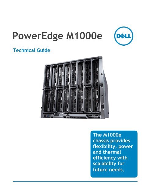
<strong>PowerEdge</strong> <strong>M1000e</strong><br />
<strong>Technical</strong> <strong>Guide</strong><br />
The <strong>M1000e</strong><br />
chassis provides<br />
flexibility, power<br />
and thermal<br />
efficiency with<br />
scalability for<br />
future needs.
<strong>Dell</strong><br />
This document is for informational purposes only. <strong>Dell</strong> reserves the right to make changes without<br />
further notice to any products herein. The content provided is as is and without express or implied<br />
warranties of any kind.<br />
<strong>Dell</strong>, <strong>PowerEdge</strong>, PowerConnect, RapidRails, VersaRails, FlexAddress, and OpenManage are<br />
trademarks of <strong>Dell</strong>, Inc. Avocent is a registered trademark of Avocent Corporation or its subsidiaries.<br />
Other trademarks and trade names may be used in this document to refer to either the entities<br />
claiming the marks and names or their products. Brocade is a registered trademark of Brocade<br />
Communications Systems, Inc., in the United States and/or in other countries. Cisco and Catalyst are<br />
registered trademarks of Cisco and/or its affiliates in the U.S. and certain other countries. Citrix®<br />
and XenServer are trademarks of Citrix Systems, Inc. and/or one or more of its subsidiaries, and<br />
may be registered in the United States Patent and Trademark Office and in other countries. Egenera<br />
registered trademarks of Egenera, Inc. in the United States and/or other countries. InfiniBand is a<br />
registered trademark and service mark of the InfiniBand Trade Association. Intel and Xeon are<br />
registered trademarks of Intel Corporation in the U.S. and other countries. Mellanox is a registered<br />
trademark of Mellanox Technologies, Inc. Microsoft, Windows Server, Active Directory, and Hyper-V<br />
are either registered trademarks or trademarks of Microsoft Corporation in the United States and/or<br />
other countries. Platespin and PowerConvert are registered trademarks of Novell, Inc., in the United<br />
States and other countries. Velcro is a registered trademark of Velcro Industries B.V. VMware is a<br />
registered trademark and vCenter is a trademark of VMware, Inc. in the United States and/or other<br />
jurisdictions. <strong>Dell</strong> disclaims proprietary interest in the marks and names of others.<br />
©Copyright 2010 <strong>Dell</strong> Inc. All rights reserved. Reproduction or translation of any part of this work<br />
beyond that permitted by U.S. copyright laws without the written permission of <strong>Dell</strong> Inc. is unlawful<br />
and strictly forbidden.<br />
Initial Release June 2010<br />
<strong>PowerEdge</strong> <strong>M1000e</strong> <strong>Technical</strong> <strong>Guide</strong> 1
<strong>Dell</strong><br />
Table of Contents<br />
1 Product Comparison ........................................................................................... 5<br />
2 New Technologies .............................................................................................. 7<br />
2.1 Overview .................................................................................................. 7<br />
2.2 Detailed Information .................................................................................... 7<br />
3 System Information ............................................................................................ 9<br />
3.1 Overview .................................................................................................. 9<br />
3.2 Product Features Summary ............................................................................. 9<br />
4 Mechanical .................................................................................................... 10<br />
4.1 Chassis Description..................................................................................... 10<br />
4.2 Dimensions and Weight ................................................................................ 10<br />
4.3 Front Panel View and Features ...................................................................... 10<br />
4.4 Back Panel Features ................................................................................... 12<br />
4.5 Power Supply Indicators ............................................................................... 12<br />
4.6 Rails and Cable Management ......................................................................... 13<br />
4.7 Rack Support ............................................................................................ 16<br />
4.8 Rack View ............................................................................................... 16<br />
4.9 Fans ...................................................................................................... 17<br />
4.10 Cabling ................................................................................................... 21<br />
4.11 Control Panel/LCD ..................................................................................... 22<br />
4.12 Security .................................................................................................. 24<br />
5 Power, Thermal, Acoustic .................................................................................. 26<br />
5.1 Power Supplies ......................................................................................... 26<br />
5.1.1 Supported Voltages .............................................................................. 27<br />
5.1.2 Redundancy ....................................................................................... 27<br />
5.1.3 Power Management .............................................................................. 29<br />
5.2 Power Supply Specifications .......................................................................... 30<br />
5.3 Heat Dissipation ........................................................................................ 30<br />
5.4 Environmental Specifications......................................................................... 33<br />
5.5 Power Consumption .................................................................................... 33<br />
5.6 Maximum Input Amps .................................................................................. 33<br />
5.7 Power-Up Sequence ................................................................................... 33<br />
5.8 Acoustics ................................................................................................ 33<br />
6 Processors and Memory ..................................................................................... 35<br />
7 Midplane ....................................................................................................... 36<br />
8 Embedded NICs/LAN on Motherboard (LOM) ............................................................. 39<br />
9 I/O ............................................................................................................. 40<br />
9.1 Overview ................................................................................................ 40<br />
9.2 Quantities and Priorities .............................................................................. 41<br />
9.3 Supported Mezzanine Cards and Switches .......................................................... 44<br />
9.4 I/O Module Installation ................................................................................ 45<br />
9.5 FlexAddress ............................................................................................. 45<br />
10 Storage ........................................................................................................ 51<br />
11 Video ........................................................................................................... 52<br />
12 Rack Information ............................................................................................. 53<br />
<strong>PowerEdge</strong> <strong>M1000e</strong> <strong>Technical</strong> <strong>Guide</strong> 2
<strong>Dell</strong><br />
12.1 Overview ................................................................................................ 53<br />
12.2 Rails ...................................................................................................... 53<br />
12.3 Cable Management Arm (CMA) ....................................................................... 54<br />
12.4 Rack View ............................................................................................... 55<br />
13 Virtualization ................................................................................................. 57<br />
14 Systems Management ........................................................................................ 59<br />
14.1 Overview ................................................................................................ 59<br />
14.2 Server Management .................................................................................... 60<br />
14.3 Enclosure Management ................................................................................ 61<br />
14.4 Integrated Keyboard and Mouse Controller (iKVM) ................................................ 65<br />
15 Peripherals .................................................................................................... 68<br />
16 Packaging Options ........................................................................................... 69<br />
Tables<br />
Table 1. Comparison of <strong>PowerEdge</strong> 1855/1955 Chassis and <strong>M1000e</strong> Chassis ............................ 5<br />
Table 2. Rack vs. Blade Server Rack-Level Specification Comparison ................................... 6<br />
Table 3. Feature Summary ..................................................................................... 9<br />
Table 4. Dimensions ........................................................................................... 10<br />
Table 5. Typical Modular Server System Rack Height and Cable Reduction ........................... 13<br />
Table 6. Fabric Specifications ................................................................................ 43<br />
Table 7. FlexAddress Features and Benefits ............................................................... 47<br />
Figures<br />
Figure 1. Server Density Comparison .......................................................................... 5<br />
Figure 2. <strong>M1000e</strong> Front View .................................................................................. 10<br />
Figure 3. Possible Server Module Sizes, Front Panel View ................................................ 11<br />
Figure 4. Example Server Module Configurations .......................................................... 11<br />
Figure 5. Power Supply Indicators ............................................................................ 12<br />
Figure 6. Rack Cabling ......................................................................................... 14<br />
Figure 7. RapidRails Rack Kit Contents ...................................................................... 15<br />
Figure 8. VersaRails Rack Kit Contents ...................................................................... 15<br />
Figure 9. <strong>M1000e</strong> in a Rack .................................................................................... 16<br />
Figure 10. Rear View Showing Fans ......................................................................... 17<br />
Figure 11. Blades, Blanks, and 1 Open Slot Needing to be Filled ...................................... 18<br />
Figure 12. Power Supply, Power Supply Blanks, and Open Slot Needing to be Filled ............... 18<br />
Figure 13. I/O Module and Open Slot Needing to be Filled ............................................. 19<br />
Figure 14. Installed CMC, I/O Module, and Power Supply Blanks ...................................... 20<br />
Figure 15. Installed iKVM Blank ............................................................................. 20<br />
Figure 16. Power Supply, CMC, and I/O Module Blanks .................................................. 21<br />
Figure 17. Simplified Cabling ................................................................................ 22<br />
Figure 18. <strong>M1000e</strong> LCD Panel Recessed Position ......................................................... 23<br />
Figure 19. <strong>M1000e</strong> LCD Panel During Usage ............................................................... 23<br />
Figure 20. LCD Panel Capabilities ........................................................................... 24<br />
Figure 21. Power Supplies in <strong>M1000e</strong> ....................................................................... 26<br />
Figure 22. <strong>M1000e</strong> Power Supply Rear View ............................................................... 27<br />
<strong>PowerEdge</strong> <strong>M1000e</strong> <strong>Technical</strong> <strong>Guide</strong> 3
<strong>Dell</strong><br />
Figure 23. Power Architecture .............................................................................. 28<br />
Figure 24. PMBus Communication Channels ............................................................... 30<br />
Figure 25. Server Cooling Air Profile ....................................................................... 31<br />
Figure 26. I/O Module Inlet and IOM Locations ........................................................... 31<br />
Figure 27. I/O Cooling Air Profile ........................................................................... 32<br />
Figure 28. Power Supply Inlet and Cooling Air Profile ................................................... 32<br />
Figure 29. Midplane ........................................................................................... 36<br />
Figure 30. <strong>M1000e</strong> Midplane Front View ................................................................... 37<br />
Figure 31. <strong>M1000e</strong> Midplane Rear View .................................................................... 38<br />
Figure 32. <strong>M1000e</strong> I/O Modules ............................................................................. 40<br />
Figure 33. High Speed I/O Architecture ................................................................... 42<br />
Figure 34. Ethernet Growth Path ........................................................................... 43<br />
Figure 35. Difference Between Passthroughs and Switch Modules ..................................... 44<br />
Figure 36. FlexAddress Addresses ........................................................................... 46<br />
Figure 37. FlexAddress Screen in the CMC ................................................................. 47<br />
Figure 38. FlexAddress SD Card ............................................................................. 48<br />
Figure 39. SD Slot on bottom of CMC ....................................................................... 48<br />
Figure 40. CMC FlexAddress Summary Screen ............................................................. 49<br />
Figure 41. CMC FlexAddress Server Detail Screen ........................................................ 50<br />
Figure 42. Examples of Major Storage Platforms Supported ............................................ 51<br />
Figure 43. <strong>M1000e</strong> RapidRails Static Rails ................................................................. 53<br />
Figure 44. <strong>M1000e</strong> VersaRails Static Rails ................................................................. 54<br />
Figure 45. <strong>M1000e</strong> Strain Relief Bar and Cable Enumerator Clip (12 Per Kit) ........................ 55<br />
Figure 46. <strong>M1000e</strong> Mounted in the Rack ................................................................... 55<br />
Figure 47. <strong>M1000e</strong> Strain Relief Bar and Cable Enumerator Clips ...................................... 56<br />
Figure 48. Examples of Major Virtualization Platforms Supported ..................................... 57<br />
Figure 49. Examples of I/O modules Recommended for Use in Virtualized Environments ......... 58<br />
Figure 50. System Management Architecture Simplified Block Diagram .............................. 60<br />
Figure 51. Chassis Management Controller ................................................................ 63<br />
Figure 52. CMC Module Features ............................................................................ 64<br />
Figure 53. <strong>M1000e</strong> iKVM ...................................................................................... 65<br />
Figure 54. Rear iKVM interface Panel ...................................................................... 66<br />
Figure 55. Front Keyboard/Video Ports .................................................................... 66<br />
Figure 56. Enclosure After Unpacking ...................................................................... 69<br />
<strong>PowerEdge</strong> <strong>M1000e</strong> <strong>Technical</strong> <strong>Guide</strong> 4
<strong>Dell</strong><br />
1 Product Comparison<br />
The <strong>Dell</strong> <strong>PowerEdge</strong> <strong>M1000e</strong> offers significant enhancements over its predecessor, the 1955, as<br />
can be seen in the following table:<br />
Table 1. Comparison of <strong>PowerEdge</strong> 1855/1955 Chassis and <strong>M1000e</strong> Chassis<br />
Feature 1855/1955 Chassis <strong>M1000e</strong> Chassis<br />
Blade Compatibility <strong>PowerEdge</strong> 1855/1955 <strong>PowerEdge</strong> M600/M605<br />
11G and beyond<br />
Form Factor 7U 10U<br />
No. of Blades 10 16<br />
I/O Module Bay 4 6<br />
Fabric Types Supported 1 x Dual GbE<br />
1 x Dual Xaui<br />
1 Lane – GbE, FC2<br />
4 Lane – 4 x IB<br />
2 x 2 Lane to support:<br />
GbE2 x 4<br />
2 X 4 Lane to support:<br />
1 Lane – GbE, 10GbE serial/KR, FC8/4/2/1<br />
4 Lane – IB, 10GbE (Xaui. KR), 40GbE<br />
Power Supplies 2 x (non-redundant) or 4 x 2100W PSUs 3 x non-redundant) or 6 x 2360W PSUs<br />
Management Modules 1 (std) 2nd(optional) 1 (std) 2nd(optional)<br />
KVM options 1 x Avocent® Analog or Digital KVM 1 x Avocent® Analog KVM (optional)<br />
Putting 16 half-height blades in the <strong>PowerEdge</strong> <strong>M1000e</strong> is 60% more dense than using 1U servers.<br />
Figure 1. Server Density Comparison<br />
<strong>PowerEdge</strong> <strong>M1000e</strong> <strong>Technical</strong> <strong>Guide</strong> 5
<strong>Dell</strong><br />
Greater density means:<br />
• Smaller Footprint<br />
• More Processing Performance<br />
• More RAM capacity<br />
• Lower Power Consumption per unit<br />
• Easier Manageability<br />
<strong>Dell</strong>’s blade server platform offers superior feature density over comparable rack servers, as can be<br />
seen from 0. (Darker blue shading indicates increased memory density.)<br />
Table 2. Rack vs. Blade Server Rack-Level Specification Comparison 1<br />
R410 R510 R610 R710 R810 R815 R905 R910 M605 M610 M710 M805 M905 M910<br />
Form Factor Rack 2 Rack Rack Rack Rack Rack Rack Rack 1/2<br />
Blade<br />
Processors<br />
Manufacturer Intel Intel Intel Intel Intel AMD AMD Intel AMD Intel Intel AMD AMD Intel<br />
Sockets 2 2 2 2 4 4 4 4 2 2 2 2 4 4<br />
Max Cores<br />
per 42U Rack<br />
Memory<br />
Max RAM per<br />
rack, in TB<br />
I/O<br />
Max 1GB<br />
Ethernet<br />
Ports per 42U<br />
Rack<br />
Max 10GbE,<br />
DDR IB, or FC<br />
network<br />
ports per<br />
rack<br />
Internal Storage 3<br />
Drives per<br />
42U rack<br />
Max 7.2k or<br />
10k rpm<br />
internal<br />
storage per<br />
rack<br />
Max 15k rpm<br />
internal<br />
storage per<br />
42U rack<br />
Max SSD<br />
internal<br />
storage per<br />
42U rack<br />
1<br />
This rack-level physical capacity specification summary does not factor in power and cooling.<br />
2<br />
42U is the most common rack size.<br />
3<br />
Storage measurements provided in Terabytes.<br />
<strong>PowerEdge</strong> <strong>M1000e</strong> <strong>Technical</strong> <strong>Guide</strong> 6<br />
1/2<br />
Blade<br />
Full<br />
Blade<br />
Full<br />
Blade<br />
Full<br />
Blade<br />
504 252 504 252 672 1,008 240 320 768 768 384 384 768 1,024<br />
5 3 8 4 11 5 3 10 4 12 6 4 6 16<br />
252 378 504 420 588 588 320 440 512 640 576 512 512 640<br />
84 168 168 84 252 252 140 220 256 256 256 256 256 256<br />
168 252 252 168 126 126 50 160 128 128 128 64 64 64<br />
336 504 151 252 76 76 50 96 77 77 77 38 38 38<br />
101 151 37 76 18 18 15 23 19 19 19 9 9 9<br />
17 25 25 17 13 13 0 16 13 13 13 6 6 6<br />
Full<br />
Blade
<strong>Dell</strong><br />
2 New Technologies<br />
2.1 Overview<br />
The <strong>PowerEdge</strong> <strong>M1000e</strong> is designed to help customers be more efficient with time, power and<br />
cooling, investment, and system performance. It is a breakthrough <strong>Dell</strong> engineered and patentpending<br />
design that maximizes flexibility, power and thermal efficiency, system-wide availability,<br />
performance, and manageability. The chassis integrates the latest in management, I/O, power and<br />
cooling technologies in a modular, easy-to-use package. Designed from the ground up to support<br />
current and future generations of server, storage, networking, and management technologies, the<br />
<strong>PowerEdge</strong> <strong>M1000e</strong> includes the headroom necessary to scale for the future.<br />
<strong>Dell</strong> optimized the <strong>PowerEdge</strong> <strong>M1000e</strong> Modular Server Enclosure and Server Modules to:<br />
• Maximize flexibility—modular I/O, power, cooling, and management architecture.<br />
• Maximize longevity—optimized power and cooling design supports current and future<br />
generations of server modules and I/O. I/O bandwidth to support not only today’s generation<br />
of 10Gb Ethernet, 20Gbps InfiniBand and 4Gbps Fibre Channel, but up to 40Gbps QDR<br />
InfiniBand, 10Gbps Serial Ethernet, and 8Gbps Fibre Channel.<br />
• Lower total cost of ownership (TCO)—lower cost than rack-mount servers with equivalent<br />
features. Best in class power and cooling efficiency.<br />
The <strong>PowerEdge</strong> <strong>M1000e</strong> Modular Server Enclosure solution supports server modules, network,<br />
storage, and cluster interconnect modules (switches and passthrough modules), a high-performance<br />
and highly available passive midplane that connects server modules to the infrastructure<br />
components, power supplies, fans, integrated KVM and Chassis Management Controllers (CMC). The<br />
<strong>PowerEdge</strong> <strong>M1000e</strong> uses redundant and hot‐pluggable components throughout to provide maximum<br />
uptime.<br />
The <strong>M1000e</strong> provides identical and symmetric fabric options B and C for each modular server.<br />
Ethernet I/O switches support I/O sub-modules that provide external I/O flexibility of stacking ports,<br />
10GE copper ports, or 10GE optical ports. True modularity at the system and subsystem level<br />
provides simplicity of extension and enhancement, now and in the future.<br />
The main benefits to customers of these features include improved:<br />
• Data center density<br />
• Power & cooling efficiency<br />
• Flexibility<br />
• Scalability<br />
• Virtualization capability<br />
• Ease of deployment<br />
• Manageability<br />
Together, these factors enable customers to do more with their server investment.<br />
2.2 Detailed Information<br />
Virtually unlimited in scalability, the <strong>PowerEdge</strong> <strong>M1000e</strong> chassis provides ultimate flexibility in server<br />
processor and chipset architectures. Both Intel and AMD server architectures can be supported<br />
simultaneously by the <strong>M1000e</strong> infrastructure, while cutting-edge mechanical, electrical, and<br />
software interface definitions enable multi‐generational server support and expansion.<br />
The chassis features:<br />
<strong>PowerEdge</strong> <strong>M1000e</strong> <strong>Technical</strong> <strong>Guide</strong> 7
<strong>Dell</strong><br />
• A high-speed passive midplane that connects the server modules in the front and power, I/O,<br />
and management infrastructure in the rear of the enclosure.<br />
• Comprehensive I/O options to support dual links of 40 Gigabits per second today (with 4x QDR<br />
InfiniBand®) with future support of even higher bandwidth I/O devices when those<br />
technologies become available. This provides high‐speed server module connectivity to the<br />
network and storage now and well into the future.<br />
• Thorough power-management capabilities including delivering shared power to ensure full<br />
capacity of the power supplies available to all server modules.<br />
• Broad management ability including private Ethernet, serial, USB, and low-level management<br />
connectivity between the Chassis Management Controller (CMC), Keyboard/Video/Mouse<br />
(KVM) switch, and server modules.<br />
• Up to two Chassis Management Controllers (CMC‐1 is standard, CMC-2 provides optional<br />
redundancy) and 1 optional integrated Keyboard/Video/Mouse (iKVM) switch.<br />
• Up to 6 hot-pluggable, redundant Power Supplies and 9 hot-pluggable, N+1 redundant fan<br />
modules.<br />
• System Front Control panel w/ LCD panel and two USB Keyboard/Mouse and one Video ―crash<br />
cart‖ connections.<br />
<strong>PowerEdge</strong> <strong>M1000e</strong> <strong>Technical</strong> <strong>Guide</strong> 8
<strong>Dell</strong><br />
3 System Information<br />
3.1 Overview<br />
The <strong>Dell</strong> <strong>PowerEdge</strong> <strong>M1000e</strong> Modular Server Enclosure is a breakthrough in enterprise server<br />
architecture. The enclosure and its components spring from a revolutionary, ground-up design<br />
incorporating the latest advances in power, cooling, I/O, and management technologies. These<br />
technologies are packed into a highly available rack dense package that integrates into standard <strong>Dell</strong><br />
and third-party 2000mm depth racks.<br />
3.2 Product Features Summary<br />
Table 3. Feature Summary<br />
Feature Parameter<br />
Chassis Size 10U high rack mount<br />
Blades per Chassis 16 Half Height, 8 Full Height<br />
Total Blades in a 42U Rack 64 Half Height, 32 Full Height<br />
Total I/O Module Bays 6 (3 redundant or dual fabrics)<br />
Total Power Supplies 6 (3+3 redundant)<br />
Total Fan Modules 9 (8+1 redundant)<br />
Management Modules and Interfaces 2 CMCs (1+1 redundant), 1 iKVM, Front<br />
Control Panel, Graphical LCD Control<br />
Panel<br />
AC Redundancy 3+3<br />
<strong>PowerEdge</strong> <strong>M1000e</strong> <strong>Technical</strong> <strong>Guide</strong> 9<br />
2+2<br />
1+1<br />
DC Redundancy 1+1<br />
Each requires power supplies in slots<br />
1, 2, and 3 to be connected to a<br />
different grid as compared to those in<br />
slots 4, 5, and 6.<br />
2+1<br />
3+1<br />
4+1<br />
5+1<br />
Each with one extra power supply that<br />
comes online if one of the existing<br />
power supplies fails.
<strong>Dell</strong><br />
4 Mechanical<br />
4.1 Chassis Description<br />
The <strong>Dell</strong> <strong>M1000e</strong> supports up to sixteen half-height or 8 full-height server modules. The chassis guide<br />
and retention features are designed such that alternative module form factors are possible. The<br />
chassis architecture is flexible enough that server, storage, or other types of front-loading modules<br />
are possible.<br />
4.2 Dimensions and Weight<br />
Table 4. Dimensions<br />
Dimension Measurement<br />
Width, not including rack ears 447.5 mm<br />
Height 440.5 mm<br />
Depth, Rear of EIA Flange to Rear of Chassis 753.6 mm<br />
Total System Depth (Front Bezel to PS Latch) 835.99 mm<br />
4.3 Front Panel View and Features<br />
Figure 2. <strong>M1000e</strong> Front View<br />
The <strong>M1000e</strong> enclosure supports up to 16 half‐height or 8 full-height server modules, each occupying a<br />
slot accessible in the front of the enclosure. The enclosure has also been designed to accommodate<br />
other form factors, including dual-width modules.<br />
<strong>PowerEdge</strong> <strong>M1000e</strong> <strong>Technical</strong> <strong>Guide</strong> 10
<strong>Dell</strong><br />
Figure 3. Possible Server Module Sizes, Front Panel View<br />
Server Modules can be freely located within each 2 x 2 half-height quadrant. The mechanical design<br />
of the <strong>M1000e</strong> has support structures for half-height server modules above or below double-width<br />
server modules, and for half-height server modules side-by-side with full-height server modules.<br />
Figure 4. Example Server Module Configurations<br />
Server modules are accessible from the front of the <strong>M1000e</strong> enclosure. At the bottom of the<br />
enclosure is a flip-out multiple angle LCD screen for local systems management configuration, system<br />
information, and status. The front of the enclosure also contains two USB connections for USB<br />
keyboard and mouse, a video connection and the system power button. The front control panel’s USB<br />
and video ports work only when the iKVM module is installed, as the iKVM provides the capability to<br />
switch the KVM between the blades. For more information, see System Control Panel Features in the<br />
Hardware Owner’s Manual.<br />
<strong>PowerEdge</strong> <strong>M1000e</strong> <strong>Technical</strong> <strong>Guide</strong> 11
<strong>Dell</strong><br />
Fresh air plenums are at both top and bottom of the chassis. The bottom fresh air plenum provides<br />
non‐preheated air to the <strong>M1000e</strong> power supplies. The top fresh air plenum provides non‐preheated<br />
air to the CMC, iKVM and I/O modules.<br />
4.4 Back Panel Features<br />
The rear of the <strong>M1000e</strong> Enclosure contains system management, cooling, power and I/O components.<br />
At the top of the enclosure are slots for two Chassis Management Cards and one integrated KVM<br />
switch. The enclosure ships by default with a single CMC, with the option of adding a second CMC to<br />
provide a fully redundant, active‐standby fault-tolerant solution for management access and control.<br />
Interleaved in the center of the chassis are fans and I/O modules. This arrangement optimizes the<br />
balance of airflow through the system, allowing lower pressure build-up in the system and resulting<br />
in lower airflow requirements for the fans. For more information, see Back-Panel Features in the<br />
Hardware Owner’s Manual.<br />
4.5 Power Supply Indicators<br />
Figure 5 shows the power supply indicators. For more information, see Back-Panel Features in the<br />
Hardware Owner’s Manual.<br />
Figure 5. Power Supply Indicators<br />
<strong>PowerEdge</strong> <strong>M1000e</strong> <strong>Technical</strong> <strong>Guide</strong> 12
<strong>Dell</strong><br />
4.6 Rails and Cable Management<br />
RapidRails TM Static Rails for Square Hole Racks:<br />
� Supports toolless installation in 19‖ EIA-310-E compliant square hole 4-post racks including all<br />
generations of <strong>Dell</strong> racks except for the 4200 & 2400 series<br />
� Has a minimum rail depth of 703 mm<br />
� Provides a square-hole rack adjustment range of 712-755 mm<br />
� Includes strain relief bar and cable enumerators for managing and securing cables<br />
VersaRails TM Static Rails for Square or Round Hole Racks:<br />
� Supports tooled installation in 19‖ EIA-310-E compliant square or unthreaded round hole 4post<br />
racks<br />
� Has a minimum rail depth of 703 mm<br />
� Provides a square-hole rack adjustment range of 706-755 mm<br />
� Provides a round-hole rack adjustment range of 706-755 mm<br />
� Includes strain relief bar and cable enumerators for managing and securing cables<br />
One of the advantages of a modular server system is the reduction in cable management needs<br />
within a rack system. The inclusion of fabric switches, integrated KVM and system management<br />
aggregation at the CMCs provides six‐fold or better cable reduction. The following table shows a<br />
comparison of a typical reduction available when using the <strong>M1000e</strong> Modular system with integrated<br />
switches, compared to traditional ―rack and stack‖ components. The configuration in the table<br />
assumes a server with four Ethernet ports and two Fibre Channel ports. In support of the <strong>M1000e</strong>,<br />
<strong>Dell</strong> offers a modular system cable management system to ease system installation in <strong>Dell</strong> or other<br />
industry-standard racks.<br />
Component<br />
Table 5. Typical Modular Server System Rack Height and Cable Reduction<br />
Rack<br />
Height<br />
AC power<br />
cables Ethernet Cables FC Cables KVM Cables<br />
2 socket server 1Ux16 2x16 4x16 2x16 USBx16 + VGAx16<br />
KVM 1U 1 ‐ ‐ USBx1 + VGAx1<br />
Ethernet Switches 1Ux4 1x4 4x4 ‐ ‐<br />
FC Switches 1Ux2 1x2 ‐ 2x2 ‐<br />
Total Rack 23U height 39 AC cables 72 Ethernet Cables 36 FC Cables USBx17 + VGAx17<br />
<strong>M1000e</strong> Equivalent 10U height 6 AC cables 16 Ethernet Cables 4 FC Cables USBx1 + VGAx1<br />
<strong>PowerEdge</strong> <strong>M1000e</strong> <strong>Technical</strong> <strong>Guide</strong> 13
<strong>Dell</strong><br />
Figure 6. Rack Cabling<br />
RapidRails TM Static Rails for Square Hole Racks supports toolless installation in 19‖ EIA-310-E<br />
compliant square hole 4-post racks including all generations of <strong>Dell</strong> racks except for the 4200 &<br />
2400 series. Minimum rail depth is 703 mm. Square-hole rack adjustment range is 712–755 mm.<br />
The rail system includes a strain relief bar and cable enumerators for managing and securing<br />
cables.<br />
<strong>PowerEdge</strong> <strong>M1000e</strong> <strong>Technical</strong> <strong>Guide</strong> 14
<strong>Dell</strong><br />
See Section 12 for more details.<br />
Figure 7. RapidRails Rack Kit Contents<br />
Figure 8. VersaRails Rack Kit Contents<br />
<strong>PowerEdge</strong> <strong>M1000e</strong> <strong>Technical</strong> <strong>Guide</strong> 15
<strong>Dell</strong><br />
4.7 Rack Support<br />
The <strong>M1000e</strong> chassis offers the following options for rack support:<br />
• RapidRails static rails for toolless mounting in 4-post racks with square holes<br />
• VersaRails static rails for tooled mounting in 4-post racks with square or unthreaded round<br />
holes<br />
See Section 12 for more details.<br />
4.8 Rack View<br />
Figure 9. <strong>M1000e</strong> in a Rack<br />
<strong>PowerEdge</strong> <strong>M1000e</strong> <strong>Technical</strong> <strong>Guide</strong> 16
<strong>Dell</strong><br />
4.9 Fans<br />
`<br />
Figure 10. Rear View Showing Fans<br />
The <strong>PowerEdge</strong> <strong>M1000e</strong> chassis comes standard with 9 hot-swappable, redundant fan modules that<br />
are distributed evenly across the enclosure. The speed of each fan is individually managed by the<br />
CMC. Together, these design innovations can provide:<br />
• Significant power savings as compared to older servers<br />
• Less airflow required as compared to the same number of similarly configured 1U servers<br />
• A similar acoustic profile as compared to previous servers<br />
Fans are N+1 redundant, meaning that any single fan can fail without impacting system uptime or<br />
reliability. In the event of a fan failure, system behavior is dependent on the resultant temperatures<br />
of the system, as monitored by the Server Module iDRAC and I/O Modules. The CMC continues to<br />
interpret the airflow needs of each server and I/O module to control the fan speeds appropriately.<br />
The system will not ramp the fans to full speed in the event of a fan failure unless deemed necessary<br />
by on‐board monitoring. Failure of more than one fan will not automatically result in shutting down<br />
of blade servers. This is because the blade servers have their own self-protection mechanisms to<br />
prevent them from running too hot. The result of a failure of multiple fans would depend on the<br />
configuration, ambient temperature, and workload being run. For example, the processors within a<br />
blade are automatically throttled back by that server if they reach a thermal threshold and then shut<br />
down if a critical over-temperature threshold is met.<br />
<strong>PowerEdge</strong> <strong>M1000e</strong> <strong>Technical</strong> <strong>Guide</strong> 17
<strong>Dell</strong><br />
Note:<br />
The blank blade, hard drive, and server I/O fillers for every blank slot are required for<br />
cooling/airflow reasons.<br />
Figure 11. Blades, Blanks, and 1 Open Slot Needing to be Filled<br />
Figure 12. Power Supply, Power Supply Blanks, and Open Slot Needing to be Filled<br />
<strong>PowerEdge</strong> <strong>M1000e</strong> <strong>Technical</strong> <strong>Guide</strong> 18
<strong>Dell</strong><br />
Figure 13. I/O Module and Open Slot Needing to be Filled<br />
<strong>PowerEdge</strong> <strong>M1000e</strong> <strong>Technical</strong> <strong>Guide</strong> 19
<strong>Dell</strong><br />
Figure 14. Installed CMC, I/O Module, and Power Supply Blanks<br />
Figure 15. Installed iKVM Blank<br />
<strong>PowerEdge</strong> <strong>M1000e</strong> <strong>Technical</strong> <strong>Guide</strong> 20
<strong>Dell</strong><br />
4.10 Cabling<br />
Figure 16. Power Supply, CMC, and I/O Module Blanks<br />
There are two types of external cabling simplification features offered:<br />
• Stacked Ethernet Switching<br />
o Internal switches have optional 10GbE uplinks and/or stacking connectors<br />
o Manage/configure multiple switches as one with stacking<br />
o Consolidate uplinks from multiple chassis into 2-4 x 10GbE ports<br />
• Stacked CMCs<br />
o CMC has a 2nd Ethernet port for connection to other CMCs in the rack<br />
o CMC connects to the management network to manage all blade servers<br />
o Saves port consumption on external switches<br />
<strong>PowerEdge</strong> <strong>M1000e</strong> <strong>Technical</strong> <strong>Guide</strong> 21
<strong>Dell</strong><br />
4.11 Control Panel/LCD<br />
Figure 17. Simplified Cabling<br />
The control panel contains the local user interface. Functions include chassis level diagnostic LEDs,<br />
LCD panel, and power button. This device is hot-pluggable and is always powered, even in chassis<br />
standby mode.<br />
<strong>PowerEdge</strong> <strong>M1000e</strong> <strong>Technical</strong> <strong>Guide</strong> 22
<strong>Dell</strong><br />
Figure 18. <strong>M1000e</strong> LCD Panel Recessed Position<br />
Figure 19. <strong>M1000e</strong> LCD Panel During Usage<br />
The <strong>M1000e</strong> chassis LCD shows extensive information about the status of each hardware module,<br />
network information for the CMC and each iDRAC, and status messages with detailed explanations in<br />
plain language. Users may access a wide variety of information about modules via the panel,<br />
including their type, user-defined name, configurations, service tag numbers, and IP address<br />
<strong>PowerEdge</strong> <strong>M1000e</strong> <strong>Technical</strong> <strong>Guide</strong> 23
<strong>Dell</strong><br />
information. The LCD panel can be retracted into the chassis body, or extended and angled once<br />
deployed for full visibility no matter where the <strong>M1000e</strong> is mounted in the rack.<br />
The LCD panel can be used as a diagnostic source and as a place to configure parameters of certain<br />
chassis components as well as the server’s iDRAC network configuration.<br />
Figure 20 shows some of the capabilities of the LCD control panel.<br />
Figure 20. LCD Panel Capabilities<br />
The primary function of the LCD panel is to provide real-time information on the health and status of<br />
the modules in the enclosure. LCD panel features include:<br />
• A deployment setup wizard that allows you to configure the CMC module’s network settings<br />
during initial system set up<br />
• Menus to configure the iDRAC in each blade<br />
• Status information screens for each blade<br />
• Status information screens for the modules installed in the back of the enclosure, including<br />
the IO modules, fans, CMC, iKVM, and power supplies<br />
• A network summary screen listing the IP addresses of all components in the system<br />
• Real time power consumption statistics, including high and low values and average power<br />
consumption<br />
• Ambient temperature values<br />
• AC power information<br />
• Critical failure alerts and warnings<br />
See the <strong>M1000e</strong> Configuration <strong>Guide</strong> and the CMC Administrator Reference <strong>Guide</strong> for more details on<br />
the capabilities of the LCD panel.<br />
4.12 Security<br />
The <strong>M1000e</strong> offers many security features, including the ability to:<br />
• Assign one admin per blade or one admin per multiple blades<br />
• Grant permissions to some blades but not to others<br />
• Customize administrative access for CMC, iDRAC, and I/O<br />
<strong>PowerEdge</strong> <strong>M1000e</strong> <strong>Technical</strong> <strong>Guide</strong> 24
<strong>Dell</strong><br />
Most of the security capabilities are driven by the CMC, which provides a mechanism for centralized<br />
configuration of the <strong>M1000e</strong> enclosure’s security settings and user access. It is secured by a usermodifiable<br />
password. The CMC’s security features include:<br />
• User authentication through optional Active Directory and LDAP services or hardware-stored<br />
user IDs and passwords<br />
• Role-based authority, which enables an administrator to configure specific privileges for each<br />
user<br />
• User ID and password configuration through the Web interface<br />
• Web interface supports 128-bit SSL 3.0 encryption and 40-bit SSL 3.0 encryption (for countries<br />
where 128-bit is not acceptable)<br />
• Configurable IP ports (where applicable)<br />
• Login failure limits per IP address, with login blocking from the IP address when the limit is<br />
exceeded<br />
• Configurable session auto time out and number of simultaneous sessions<br />
• Limited IP address range for clients connecting to the CMC<br />
• Secure Shell (SSH), which uses an encrypted layer for higher security<br />
• Single Sign-on, Two-Factor Authentication, and Public Key Authentication<br />
• Disabling front panel access<br />
<strong>PowerEdge</strong> <strong>M1000e</strong> <strong>Technical</strong> <strong>Guide</strong> 25
<strong>Dell</strong><br />
5 Power, Thermal, Acoustic<br />
Built on <strong>Dell</strong> Energy Smart technology, the <strong>M1000e</strong> is one of the most power-efficient blade solutions<br />
on the market. The <strong>M1000e</strong> enclosure takes advantage of Energy Smart thermal design efficiencies,<br />
such as ultra-efficient power supplies and dynamic power-efficient fans with optimized airflow<br />
design to efficiently cool the chassis and enable better performance in a lower power envelope.<br />
A modular system has many advantages over standard rack mount servers in terms of power<br />
optimization, and this aspect was a focal point throughout the <strong>M1000e</strong>’s conceptualization and<br />
development. The key areas of interest are power delivery and power management.<br />
The <strong>M1000e</strong> provides industry-leading power efficiency and density, accomplished through highly<br />
efficient components, improved design techniques, and a fresh air plenum that reduces the air<br />
temperature to the power supply components. Lower operating temperature equates to higher power<br />
density for the power supply (exceeding 21 Watts per cubic inch) and higher power efficiency (better<br />
than 87% at 20% load and higher at heavier loads, approaching 91% efficiency under normal operating<br />
conditions).<br />
Power efficiency in the <strong>M1000e</strong> does not stop with the power supply. Every aspect of efficiency has<br />
been tweaked and improved from previous designs—adding more copper to PC board power planes to<br />
reduce I2R losses, improving inductors and other components, increasing efficiencies of DC‐DC<br />
converters, and replacing some linear voltage regulators with more-efficient switching regulators.<br />
See Section 15 for more information on external power connection accessories.<br />
5.1 Power Supplies<br />
The power distribution inside the <strong>M1000e</strong> Modular Server System consists of a power supply system<br />
located in the rear bottom of the chassis.<br />
Figure 21. Power Supplies in <strong>M1000e</strong><br />
<strong>PowerEdge</strong> <strong>M1000e</strong> <strong>Technical</strong> <strong>Guide</strong> 26
<strong>Dell</strong><br />
Figure 22. <strong>M1000e</strong> Power Supply Rear View<br />
The <strong>Dell</strong> power supplies utilize output Oring FETs to isolate the power supply from the 12V system<br />
bus. If a single power supply fails its output Oring FET for that power supply will turn off removing<br />
itself from the bus. Think of it as an electrical switch that turns off when the power supply fails.<br />
5.1.1 Supported Voltages<br />
<strong>Dell</strong> currently offers a power supply rated at 2360W 230V. With current sharing between power<br />
supplies, total system redundant power is approximately 7080W in a 3+3 power supply configuration.<br />
5.1.2 Redundancy<br />
Power redundancy in the <strong>M1000e</strong> supports any necessary usage model, though the <strong>M1000e</strong> requires<br />
three power supplies to power a fully populated system or six power supplies in a fully redundant<br />
system.<br />
AC redundancy is supported in the following configurations, each of which requires the power<br />
supplies in slots 1, 2, and 3 to be connected to a different grid as compared to those in slots 4, 5,<br />
and 6.<br />
• 3+3<br />
• 2+2<br />
• 1+1<br />
DC redundancy is supported in the following configurations, each with one extra power supply that<br />
comes online if one of the existing power supplies fails:<br />
<strong>PowerEdge</strong> <strong>M1000e</strong> <strong>Technical</strong> <strong>Guide</strong> 27
<strong>Dell</strong><br />
• 1+1<br />
• 2+1<br />
• 3+1<br />
• 4+1<br />
• 5+1<br />
When Dynamic Power Supply Engagement (DPSE) is enabled, the PSU units move between On and Off<br />
states depending upon actual power draw conditions to achieve high power efficiency by driving<br />
fewer supplies to maximum versus all with partial and less-efficient loading.<br />
In the N+N power supply configuration, the system will provide protection against AC grid loss or<br />
power supply failures. If one power grid fails, three power supplies lose their AC source, and the<br />
three power supplies on the other grid remain powered, providing sufficient power for the system to<br />
continue running. In the N+1 configuration only power supply failures are protected, not grid<br />
failures. The likelihood of multiple power supplies failing at the same time is remote. In the N+0<br />
configuration there is no power protection and any protection must be provided at the node or<br />
chassis level. Typically this case is an HPCC or other clustered environment where redundant power<br />
is not a concern, since the parallelism of the processing nodes across multiple system chassis<br />
provides all the redundancy that is necessary.<br />
The midplane carries all 12 Volt DC power for the system, both main power and standby power. The<br />
CMCs, LCD and Control Panel are powered solely by 12 Volt Standby power, insuring that chassis level<br />
management is operational in the chassis standby state, whenever AC power is present. The server<br />
modules, I/O Modules, Fans, and iKVM are powered solely by 12 Volt Main power.<br />
Figure 23. Power Architecture<br />
<strong>PowerEdge</strong> <strong>M1000e</strong> <strong>Technical</strong> <strong>Guide</strong> 28
<strong>Dell</strong><br />
5.1.3 Power Management<br />
Power is no longer just about power delivery, it is also about power management. The <strong>M1000e</strong><br />
System offers many advanced power management features. Most of these features operate<br />
transparently to the user, while others require only a one time selection of desired operating modes.<br />
Shared power takes advantage of the large number of resources in the modular server, distributing<br />
power across the system without the excess margin required in dedicated rack mount servers and<br />
switches. The <strong>M1000e</strong> has an advanced power budgeting feature, controlled by the CMC and<br />
negotiated in conjunction with the iDRAC on every server module. Prior to any server module<br />
powering up, through any of its power up mechanisms such as AC recovery, WOL or a simple power<br />
button press, the server module iDRAC performs a sophisticated power budget inventory for the<br />
server module, based upon its configuration of CPUs, memory, I/O and local storage. Once this<br />
number is generated, the iDRAC communicates the power budget inventory to the CMC, which<br />
confirms the availability of power from the system level, based upon a total chassis power inventory,<br />
including power supplies, iKVM, I/O Modules, fans and server modules. Since the CMC controls when<br />
every modular system element powers on, it can set power policies on a system level.<br />
In coordination with the CMC, iDRAC hardware constantly monitors actual power consumption at<br />
each server module. This power measurement is used locally by the server module to insure that its<br />
instantaneous power consumption never exceeds the budgeted amount. While the system<br />
administrator may never notice these features in action, what they enable is a more aggressive<br />
utilization of the shared system power resources. Thus the system is never ―flying blind‖ in regards<br />
to power consumption, and there is no danger of exceeding power capacity availability, which could<br />
result in a spontaneous activation of power supply over current protection without these features.<br />
The system administrator can also set priorities for each server module. The priority works in<br />
conjunction with the CMC power budgeting and iDRAC power monitoring to insure that the lowest<br />
priority blades are the first to enter any power optimization mode, should conditions warrant the<br />
activation of this feature.<br />
Power capping is set at the chassis level for our blade servers and not at the blade server level, so<br />
components like processer, memory can throttle down when necessary on lower priority blade<br />
servers. An allocation is taken out for the infrastructure (fans, IO modules) and then the remainder is<br />
applied to the blades, and then throttling is applied if required to get under the cap. If all the blades<br />
are setup with the same priority, then it will start throttling down processor, memory, and so on. A<br />
variety of BIOS settings will throttle the processor or not depending on load:<br />
If power consumption demands exceed available power, the enclosure ―throttles‖ back the power<br />
supplied to blades as prioritized in the CMC. The blades will not shut down; rather they will slow<br />
down if necessary; <strong>Dell</strong> designed the system this way on purpose, in response to customer feedback<br />
that they did not want the blades to shut themselves down under any condition. I/O modules, on the<br />
other hand, will shut down prior to permanent damage, as they are less tolerant to power variation<br />
than the blade server hardware.<br />
The <strong>M1000e</strong> is compliant with the PMBus Specification 1.1, using this power management standard<br />
for status, measurement and control. The <strong>M1000e</strong> power supplies continuously monitor AC input<br />
current, voltage and power, enabling exposure of data to <strong>Dell</strong> OpenManage IT Assistant or to other<br />
enterprise-level management tools. Real time power consumption is viewable per system.<br />
<strong>PowerEdge</strong> <strong>M1000e</strong> <strong>Technical</strong> <strong>Guide</strong> 29
<strong>Dell</strong><br />
Figure 24. PMBus Communication Channels<br />
All VMware® products include consuming the "current power consumption" and "current power<br />
cap/limit" retrieval via <strong>Dell</strong> specific IPMI commands using iDRAC. They are using this to report the<br />
total power consumed by the server and also using this as part of their calculations to<br />
determine/approximate the VM-level power.<br />
The Power Management chapter in the <strong>Dell</strong> Chassis Management Controller (CMC) User <strong>Guide</strong><br />
provides extensive information on power management.<br />
5.2 Power Supply Specifications<br />
Each power supply offers:<br />
• 91%+ AC/DC Conversion Efficiency<br />
• Dynamic Power Supply Engagement which automatically engages the minimum number of<br />
supplies required to power a given configuration, maximizing power supply efficiency<br />
The following are the <strong>PowerEdge</strong> M-1000e chassis power supply capabilities:<br />
• 2360 watts maximum for each PSU<br />
• 220 VAC (Volts Alternate Current) input (a single PSU runs between 180V and 260V AC)<br />
• 50Hz or 60Hz input<br />
• 14A maximum input<br />
• 192A (Amps) @ + 12 Volts DC ( Direct Current) output Operational<br />
• 4.5A @ +12 Volt output Standby<br />
• 3 or 6 PSU configurations available<br />
• PSUs are hot-swappable<br />
5.3 Heat Dissipation<br />
The cooling strategy for the <strong>M1000e</strong> supports a low‐impedance, high‐efficiency design philosophy.<br />
Driving lower airflow impedance allows the <strong>M1000e</strong> to draw air through the system at a lower<br />
operating pressure and reduces the system fan power consumed to meet the airflow requirements of<br />
the system.<br />
The low impedance design is coupled with a high‐efficiency air-moving device designed explicitly for<br />
the <strong>PowerEdge</strong> <strong>M1000e</strong> chassis. The efficiency of an air-moving device is defined as the work output<br />
<strong>PowerEdge</strong> <strong>M1000e</strong> <strong>Technical</strong> <strong>Guide</strong> 30
<strong>Dell</strong><br />
of the fan as compared to the electrical power required to run the fan. The <strong>M1000e</strong> fan operates at<br />
extreme efficiencies which correlates directly into savings in the customer’s required power‐to‐cool.<br />
The high‐efficiency design philosophy also extends into the layout of the subsystems within the<br />
<strong>M1000e</strong>. The Server Modules, I/O Modules, and Power Supplies are incorporated into the system with<br />
independent airflow paths. This isolates these components from pre‐heated air, reducing the<br />
required airflow consumptions of each module.<br />
Figure 25. Server Cooling Air Profile<br />
The Server Modules are cooled with traditional front‐to‐back cooling. As shown in the figure, the<br />
front of the system is dominated by inlet area for the individual server modules. The air passes<br />
through the server modules, through venting holes in the midplane, and is then drawn into the fans<br />
which exhaust the air from the chassis. There are plenums both upstream of the midplane, between<br />
the midplane and the blades, and downstream of the midplane, between the midplane and the fans,<br />
to more evenly distribute the cooling potential from the three columns of fans across the server<br />
modules.<br />
Figure 26. I/O Module Inlet and IOM Locations<br />
<strong>PowerEdge</strong> <strong>M1000e</strong> <strong>Technical</strong> <strong>Guide</strong> 31
<strong>Dell</strong><br />
Figure 27. I/O Cooling Air Profile<br />
The I/O Modules use a bypass duct to draw ambient air from the front of the system to the I/O<br />
Module inlet, as seen in the figure. This duct is located above the server modules. This cool air is<br />
then drawn down through the I/O Modules in a top to bottom flow path and into the plenum between<br />
the midplane and fans, from where it is exhausted from the system.<br />
Figure 28. Power Supply Inlet and Cooling Air Profile<br />
The Power Supplies, located in the rear of the system, use basic front‐to‐back cooling, but draw<br />
their inlet air from a duct located beneath the server modules, as seen in the figure above. This<br />
insures that the power supplies receive ambient temperature air.<br />
<strong>PowerEdge</strong> <strong>M1000e</strong> <strong>Technical</strong> <strong>Guide</strong> 32
<strong>Dell</strong><br />
This hardware design is coupled with a thermal cooling algorithm that incorporates the following:<br />
• Server module level thermal monitoring by the iDRAC<br />
• I/O module thermal health monitors<br />
• Fan control and monitoring by the CMC<br />
The iDRAC on each server module calculates the amount of airflow required on an individual server<br />
module level and sends a request to the CMC. This request is based on temperature conditions on the<br />
server module, as well as passive requirements due to hardware configuration. Concurrently, each<br />
IOM can send a request to the CMC to increase or decrease cooling to the I/O subsystem. The CMC<br />
interprets these requests, and can control the fans as required to maintain Server and I/O Module<br />
airflow at optimal levels.<br />
5.4 Environmental Specifications<br />
See the Getting Started <strong>Guide</strong> on support.dell.com.<br />
5.5 Power Consumption<br />
Use the <strong>Dell</strong> Energy Smart Solution Advisor (ESSA) to see requirements for a specific chassis<br />
configuration.<br />
5.6 Maximum Input Amps<br />
See Power Distribution Systems for the <strong>Dell</strong> <strong>M1000e</strong> Modular Server Enclosure – Selection and<br />
Installation.<br />
5.7 Power-Up Sequence<br />
The following steps detail how and in what order the <strong>M1000e</strong> components are powered up:<br />
1. The first power supply provides a small amount of electricity which starts up the first CMC.<br />
2. CMC begins to boot and power up the power supply units.<br />
3. Active and Standby CMC boot up Linux® operating system.<br />
4. Active CMC powers up all remaining PSUs.<br />
5. All six PSUs are powered up.<br />
6. Server iDRAC are powered up. (In slot priority order from 1–9; i.e., highest priority 1 slots<br />
first, then priority 2, etc. If all same priority, goes in slot order 1–16. Each one is spaced apart<br />
by 500ms.)<br />
7. iKVM is powered up.<br />
8. IOM modules are powered up.<br />
9. Depending upon Blade BIOS power setting (last power state, always on or always off), blade<br />
iDRAC requests power up from CMC first come/first served in order from #6.<br />
10. CMC powers up blades.<br />
For full configuration, booting the enclosure takes between 2–4 minutes, followed by 1–4 minutes for<br />
each blade.<br />
5.8 Acoustics<br />
The <strong>M1000e</strong> is engineered for sound quality in accordance with the <strong>Dell</strong> Enterprise acoustical<br />
specification. Compared to previous generations of products, the fans have more levels of control<br />
and finer tuning of the fan behavior. Firmware is optimized to choose the lowest fan speeds and<br />
<strong>PowerEdge</strong> <strong>M1000e</strong> <strong>Technical</strong> <strong>Guide</strong> 33
<strong>Dell</strong><br />
therefore the lowest acoustical output for any configuration (components installed), operating<br />
condition (applications being run), and ambient temperature. Because acoustical output is<br />
dependent and indeed minimized for each combination of these variables, no single acoustical level<br />
(sound pressure level or sound power level) represents the <strong>M1000e</strong>, and instead boundaries on sound<br />
power level are provided below:<br />
• Lowest Fan Speed: Upper Limit A-weighted Sound Power Level, LwA-UL, is 7.5 bels<br />
• Full Fan Speed: Upper Limit A-weighted Sound Power Level, LwA-UL, is 9.7 bels<br />
• LwA-UL is the upper limit sound power level (LwA) calculated per section 4.4.2 of ISO 9296<br />
(1988) and measured in accordance to ISO 7779 (1999)<br />
• Acoustical models have been provided to predict performance between these bounds in the<br />
ESSA tool: http://solutions.dell.com/<strong>Dell</strong>StarOnline/Launch.aspx/ESSA<br />
A few things to be aware of:<br />
• Fans are loud when running at full speed. It is rare that fans need to run at full speed. Please<br />
ensure that components are operating properly if fans remain at full speed.<br />
• The CMC will automatically raise and lower the fan speed to a setting that is appropriate to<br />
keep all modules cool.<br />
• If a single fan is removed, all fans will be set to 50% speed if the enclosure is in Standby<br />
mode; if the enclosure is powered on, removal of a single fan is treated like a failure (nothing<br />
happens).<br />
• Re-installation of a fan will cause the rest of the fans to settle back to a quieter state.<br />
• Whenever communication to the CMC or iDRAC is lost such as during firmware update, the fan<br />
speed will increase and create more noise.<br />
<strong>PowerEdge</strong> <strong>M1000e</strong> <strong>Technical</strong> <strong>Guide</strong> 34
<strong>Dell</strong><br />
6 Processors and Memory<br />
With the addition of the <strong>PowerEdge</strong> M910 server to the <strong>PowerEdge</strong> portfolio, the <strong>M1000e</strong> is now<br />
scalable to 256 cores & 4TB of RAM: 4 sockets x 8 cores x 8 blades = 256 Cores; 32 DIMM sockets x<br />
16GB DIMMs x 8 Blades = 4096GB or 4TB RAM.<br />
See the <strong>Technical</strong> <strong>Guide</strong> for each of the compatible blade servers offered for more details on<br />
processors and memory offered.<br />
<strong>PowerEdge</strong> <strong>M1000e</strong> <strong>Technical</strong> <strong>Guide</strong> 35
<strong>Dell</strong><br />
7 Midplane<br />
Though hidden from view in an actively running system, the midplane is the focal point for all<br />
connectivity within the <strong>M1000e</strong> Modular System. The midplane is a large printed circuit board<br />
providing power distribution, fabric connectivity, and system management infrastructure.<br />
Additionally it allows airflow paths for the front-to-back cooling system through ventilation holes.<br />
Figure 29. Midplane<br />
As is requisite for fault-tolerant systems, the <strong>M1000e</strong> midplane is completely passive, with no hidden<br />
stacking midplanes or interposers with active components. I/O fabrics and system management are<br />
fully redundant from each hot pluggable item. The system management Ethernet fabric is fully<br />
redundant when two CMCs are installed, with two point-to-point connections from each server<br />
module.<br />
The midplane serves as transport for a patent-pending, time-division–multiplexed serial bus for<br />
general purpose I/O reduction. This serial bus contributes greatly to the midplane’s I/O lane count<br />
reduction, which is typically burdened with a significant I/O pin and routing channel count of largely<br />
static or low-speed functions. For instance, all Fibre Channel I/O Passthrough module LED and SFP<br />
status information is carried over this bus, which alone eliminates over one hundred point-to-point<br />
connections that would otherwise be required. The time division multiplexed serial bus is fully<br />
redundant, with health monitoring, separate links per CMC and error checking across all data.<br />
<strong>PowerEdge</strong> <strong>M1000e</strong> <strong>Technical</strong> <strong>Guide</strong> 36
<strong>Dell</strong><br />
Figure 30. <strong>M1000e</strong> Midplane Front View<br />
The system is designed for receptacles on all midplane connectors and pins on all pluggable<br />
components, so any potential for bent pins is limited to the pluggable field replaceable unit, not to<br />
the system. This contributes to the high reliability and uptime of the <strong>M1000e</strong> modular system.<br />
The midplane is physically attached to the enclosure front structural element. It is aligned by<br />
guide‐pins and edges in all 3 axes. This provides close tolerance alignment between the server<br />
modules and their midplane connections. The midplane has been carefully designed to minimize the<br />
impact to the overall system airflow.<br />
<strong>PowerEdge</strong> <strong>M1000e</strong> <strong>Technical</strong> <strong>Guide</strong> 37
<strong>Dell</strong><br />
Figure 31. <strong>M1000e</strong> Midplane Rear View<br />
All <strong>M1000e</strong> midplane routing is fully isolated, supporting all chassis power, fabric, system<br />
management, and fault-tolerance requirements.<br />
<strong>PowerEdge</strong> <strong>M1000e</strong> <strong>Technical</strong> <strong>Guide</strong> 38
<strong>Dell</strong><br />
8 Embedded NICs/LAN on Motherboard (LOM)<br />
See the <strong>Technical</strong> <strong>Guide</strong> for each of the compatible blade servers.<br />
<strong>PowerEdge</strong> <strong>M1000e</strong> <strong>Technical</strong> <strong>Guide</strong> 39
<strong>Dell</strong><br />
9 I/O<br />
9.1 Overview<br />
<strong>Dell</strong> M-series provides complete, snap-in FlexI/O scalability down to the switch interconnects. Flex<br />
I/O technology is the foundation of the <strong>M1000e</strong> I/O subsystem. Customers may mix and match I/O<br />
modules, including Cisco®, <strong>Dell</strong> PowerConnect, Fibre Channel, and InfiniBand options. The I/O<br />
modules may be installed singly or in redundant pairs. See I/O Connectivity in the Hardware Owner’s<br />
Manual for detailed information.<br />
Figure 32. <strong>M1000e</strong> I/O Modules<br />
These I/O modules are connected to the blades through three redundant I/O fabrics. The enclosure<br />
was designed for 5+ years of I/O bandwidth and technology.<br />
The I/O system offers customers a wide variety of options to meet nearly any network need:<br />
• Complete, on-demand switch design<br />
• Easily scale to provide additional uplink and stacking functionality<br />
• No need to waste your current investment with a ―rip and replace‖ upgrade<br />
• Flexibility to scale Ethernet stacking and throughput<br />
• Partnered Solutions with Cisco, Emulex and Brocade<br />
• Quad Data Rate InfiniBand Switch options available for HPCC<br />
• Up to 8 high-speed ports<br />
<strong>PowerEdge</strong> <strong>M1000e</strong> <strong>Technical</strong> <strong>Guide</strong> 40
<strong>Dell</strong><br />
• Cisco® Virtual Blade Switch capability<br />
• Ethernet Port Aggregator<br />
• Virtualization of Ethernet ports for integration into any Ethernet fabric<br />
• Fibre Channel products from Brocade and Emulex offering powerful connectivity to <strong>Dell</strong>/EMC<br />
SAN fabrics<br />
• High-availability clustering inside a single enclosure or between two enclosures<br />
Each server module connects to traditional network topologies while providing sufficient bandwidth<br />
for multi‐generational product lifecycle upgrades. I/O fabric integration encompasses networking,<br />
storage, and interprocessor communications (IPC).<br />
9.2 Quantities and Priorities<br />
There are three supported high-speed fabrics per <strong>M1000e</strong> half‐height server module, with two<br />
flexible fabrics using optional plug-in mezzanine cards on the server, and one connected to the LOMs<br />
on the server. The ports on the server module connect via the midplane to the associated I/O<br />
Modules (IOM) in the rear of the enclosure, which then connect to the customer’s LAN/SAN/IPC<br />
networks.<br />
The optional mezzanine cards are designed to connect via 8-lane PCIe to the server module’s chipset<br />
in most cases. Mezzanine cards may have either one dual port ASIC with 4- or 8-lane PCIe interfaces<br />
or dual ASICs, each with 4-lane PCIe interfaces. External fabrics are routed through high-speed, 10-<br />
Gigabit-per-second–capable air dielectric connector pins through the planar and midplane. For best<br />
signal integrity, the signals isolate transmit and receive signals for minimum crosstalk. Differential<br />
pairs are isolated with ground pins and signal connector columns are staggered to minimize signal<br />
coupling.<br />
The <strong>M1000e</strong> system management hardware and software includes Fabric Consistency Checking,<br />
preventing the accidental activation of any misconfigured fabric device on a server module. The<br />
system will automatically detect this misconfiguration and alert the user of the error. No damage<br />
occurs to the system, and the user will have the ability to reconfigure the faulted module.<br />
<strong>M1000e</strong> I/O is fully scalable to current and future generations of server modules and I/O Modules.<br />
There are three redundant multi‐lane fabrics in the system, as illustrated in Figure 33.<br />
In its original configuration, the <strong>M1000e</strong> midplane is enabled to support up to four Gigabit Ethernet<br />
links per server module on Fabric A. Thus, potential data bandwidth for Fabric A is 4 Gbps per halfheight<br />
server module. A future midplane upgrade may enable higher bandwidth on Fabric A.<br />
The <strong>M1000e</strong> provides full 10/100/1000M Ethernet support when using Ethernet passthrough modules<br />
enabling you to connect to any legacy infrastructure whether using Ethernet passthrough or switch<br />
technology. This technical advance uses in-band signaling on 1000BASE‐KX transport and requires no<br />
user interaction for enablement.<br />
<strong>PowerEdge</strong> <strong>M1000e</strong> <strong>Technical</strong> <strong>Guide</strong> 41
<strong>Dell</strong><br />
Figure 33. High Speed I/O Architecture<br />
Fabric B and C are identical, fully customizable fabrics, routed as two sets of four lanes from<br />
mezzanine cards on the server modules to the I/O Modules in the rear of the chassis. Supported<br />
bandwidth ranges from 1 to 10 Gbps per lane depending on the fabric type used.<br />
<strong>PowerEdge</strong> <strong>M1000e</strong> <strong>Technical</strong> <strong>Guide</strong> 42
<strong>Dell</strong><br />
Fabric Encoding<br />
Table 6. Fabric Specifications<br />
Symbol Rate<br />
Per Lane (Gbps)<br />
Data Rate Per<br />
Lane (Gbps)<br />
Data Rate<br />
Per Link<br />
(Gbps)<br />
Lanes Per Link<br />
Per Industry<br />
Specification<br />
PCIe Gen1 8B/10B 2.5 2 8 (4 lane) 1,2,4,8,12,16,32<br />
PCIe Gen2 8B/10B 5 4 16 (4 lane) 1,2,4,8,12,16,32<br />
SATA 3Gbps 8B/10B 3 2.4 2.4 1<br />
SATA 6Gbps 8B/10B 6 4.8 4.8 1<br />
SAS 3Gbps 8B/10B 3 2.4 2.4 1-Any<br />
SAS 6Gbps 8B/10B 6 4.8 4.8 1-Any<br />
FC 4Gbps 8B/10B 4.25 3.4 3.4 1<br />
FC 8bps 8B/10B 8.5 6.8 6.8 1<br />
IB SDR 8B/10B 2.5 2 8 (4 lane) 4,12<br />
IB DDR 8B/10B 5 4 16 (4 lane) 4,12<br />
IB QDR 8B/10B 10 8 32 (4 lane) 4,12<br />
GbE: 1000BASE-<br />
KX<br />
10GbE:<br />
10GBASE-KX4<br />
10GbE:<br />
10GBASE-KR<br />
8B/10B 1.25 1 1 1<br />
8B/10B 3.125 2.5 10 (4 lane) 4<br />
64B/66B 10.3125 10 10 1<br />
Figure 34. Ethernet Growth Path<br />
The <strong>M1000e</strong> is designed for full support of all near-, medium- and long-term I/O infrastructure needs.<br />
While the <strong>M1000e</strong> system’s bandwidth capabilities lead the industry, the <strong>M1000e</strong> is also intelligently<br />
designed for maximum cost, flexibility and performance benefit.<br />
While Fabric A is dedicated to the server module LOMs, requiring Ethernet switch or passthrough<br />
modules for I/O slots A1 and A2, Fabrics B and C can be populated with Ethernet, Fibre Channel, or<br />
InfiniBand solutions.<br />
<strong>PowerEdge</strong> <strong>M1000e</strong> <strong>Technical</strong> <strong>Guide</strong> 43
<strong>Dell</strong><br />
I/O Modules are used as pairs, with two modules servicing each server module fabric providing a fully<br />
redundant solution. I/O Modules may be passthroughs or switches. Passthrough modules provide<br />
direct 1:1 connectivity from each LOM/mezzanine card port on each server module to the external<br />
network. Switches provide an efficient way to consolidate links from the LOM or Mezzanine cards on<br />
the server modules to uplinks into the customer’s network.<br />
Figure 35. Difference Between Passthroughs and Switch Modules<br />
For more information on the I/O module options, see the <strong>PowerEdge</strong> M-Series Blades I/O <strong>Guide</strong>.<br />
9.3 Supported Mezzanine Cards and Switches<br />
<strong>Dell</strong> supports one mezzanine design standard and one I/O Module design standard for true modular<br />
computing.<br />
The currently supported I/O modules include:<br />
• PowerConnect M6220 Switch; GbE + 10GbE uplinks & stacking<br />
• PowerConnect M6348 Switch; 48 1GbE ports + 10GbE uplinks<br />
• PowerConnect M8024 10Gb Ethernet Switch (SFP+, CX4, & 10Gbase-T uplink module options)<br />
• Cisco® Catalyst® 3032 switch; All 1GbE<br />
• Cisco Catalyst 3130g Switch; All 1GbE + stacking<br />
• Cisco Catalyst 3130x Switch; 1GbE+ 10GbE uplinks & stacking<br />
• Cisco 3130g & 3130x switches can be combined in a stack<br />
• 1Gb Ethernet Pass-Through Module<br />
• 10Gb Ethernet Pass-Through Module (SFP+)<br />
• Brocade® 8Gb Fibre Channel Switch<br />
<strong>PowerEdge</strong> <strong>M1000e</strong> <strong>Technical</strong> <strong>Guide</strong> 44
<strong>Dell</strong><br />
• 4Gb Fibre Channel Pass-Through<br />
• Mellanox® DDR (20Gb) InfiniBand Switch<br />
• Mellanox QDR (40Gb) InfiniBand Switch<br />
See the Ethernet I/O Cards page on <strong>Dell</strong>.com for supported I/O hardware.<br />
9.4 I/O Module Installation<br />
For detailed information on installing the I/O modules in your system, see the I/O Modules section in<br />
the Hardware Owner’s Manual for your specific <strong>PowerEdge</strong> server.<br />
9.5 FlexAddress<br />
FlexAddress delivers persistent storage and network identities, equipping a data center to handle<br />
predictable or even unplanned changes—increase, upgrade, or replace servers without affecting the<br />
network or storage and minimizing downtime.<br />
<strong>Dell</strong>’s patent-pending FlexAddress technology allows any M-Series blade enclosure to lock the World<br />
Wide Name (WWN) of the Fibre Channel controller and Media Access Control (MAC) of the Ethernet<br />
and iSCSI controller into a blade slot, instead of to the blade’s hardware as was done in the past. By<br />
removing the network and storage identity from the server hardware, customers are now able to<br />
upgrade and replace components or the entire server without changing the identity on the network.<br />
This technology works with any vendor’s installed I/O module as well as with <strong>Dell</strong> PowerConnect<br />
products.<br />
FlexAddress delivers the ability to:<br />
• Service a blade or IO Mezzanine card, upgrade the IO mezzanine cards to newer technology,<br />
or upgrade the entire server with new technology while maintaining the mapping to Ethernet<br />
and storage fabrics. This capability allows quick, painless connection and reduces downtime.<br />
This capability is especially powerful when operating in a boot from SAN environment.<br />
• Quickly obtain a list of all MAC/WWNs in the chassis by slot and be assured these will never<br />
change<br />
• Efficiently integrate into existing management and network infrastructure<br />
<strong>PowerEdge</strong> <strong>M1000e</strong> <strong>Technical</strong> <strong>Guide</strong> 45
<strong>Dell</strong><br />
Figure 36. FlexAddress Addresses<br />
FlexAddress replaces the factory-assigned World Wide Name/Media Access Control (WWN/MAC) IDs<br />
on a blade with WWN/MAC IDs from the FlexAddress SD card associated with that slot. This userconfigurable<br />
feature enables a choice of iSCSI MAC, Ethernet MAC, and/or WWN persistence, and<br />
thus allows blades to be swapped without affecting SAN Zoning, iSCSI zoning, or any MAC-dependent<br />
functions. The write-protected FlexAddress SD card comes provisioned with unique pool of 208 MACs<br />
and 64 WWNs. Other types of SD cards inserted into the CMC’s SD card slot are ignored.<br />
FlexAddress can be ordered with a new enclosure or implemented on one already owned by a<br />
customer through the purchase of a customer kit. If FlexAddress is purchased with the chassis, it will<br />
be installed and active when the system is powered up. In the case of an existing enclosure,<br />
FlexAddress requires the addition of one FlexAddress SD card to a CMC and an upgrade to the iDRAC<br />
firmware, Ethernet and Fibre Channel controllers’ firmware, server BIOS, and CMC firmware. All<br />
blades and CMC MUST have the correct versions of firmware to properly support this feature. When<br />
redundant CMCs are installed, it is not necessary to put such an SD card in both CMCs, since the<br />
WWN/MAC addresses are pushed to the chassis Control Panel upon enablement for redundancy; if<br />
one CMC becomes inoperable, the other CMC still has access to the WWN/MAC addresses in the<br />
Control Panel. Blades that are up and running are not affected as they already have their WWN/MACs<br />
programmed into their controllers. If a replacement of the control panel is required, the SD card will<br />
push the WWN/MACs back to it. It is important to note that the chassis Control Panel also stores CMC<br />
configuration information, so it is advisable that customers keep a backup of the CMC configuration<br />
file.<br />
<strong>PowerEdge</strong> <strong>M1000e</strong> <strong>Technical</strong> <strong>Guide</strong> 46
<strong>Dell</strong><br />
The CMC manages the following functions specific to FlexAddress:<br />
• Provides user interface for enabling or disabling the FlexAddress feature—on a per-blade-slot<br />
basis, a per-fabric basis, or both<br />
• Identifies and reports device information for each of the supported fabric types—LOMs,<br />
Ethernet, and Fibre Channel mezzanine cards<br />
• Validates all the components of the FlexAddress feature—SD card validation, System BIOS, IO<br />
controller firmware, CMC firmware, and, iDRAC firmware versions<br />
• Reports FlexAddress feature status for each of the blade slots<br />
• Provides information for both server-assigned (factory-programmed) and chassis-assigned<br />
(FlexAddress) addresses on each supported device<br />
• Logs any system-level errors that may prevent the FlexAddress feature from being used on the<br />
chassis or on a given device.<br />
Figure 37. FlexAddress Screen in the CMC<br />
Table 7. FlexAddress Features and Benefits<br />
Features Benefits<br />
Lock the World Wide Name (WWN) of the Fibre<br />
Channel controller and Media Access Control (MAC) of<br />
the Ethernet and iSCSI controller into a blade slot,<br />
instead of to the blade’s hardware<br />
Service or replace a blade or I/O mezzanine card and<br />
maintain all address mapping to Ethernet and storage<br />
fabrics<br />
Easy and highly reliable booting from Ethernet or<br />
Fibre Channel based Storage Area Networks (SANs)<br />
Easily replace blades without network management<br />
effort<br />
Ease of management<br />
An almost no-touch blade replacement<br />
All MAC/WWN/iSCSIs in the chassis will never change Fewer future address name headaches<br />
Fast & Efficient integration into existing network<br />
infrastructure<br />
No need to learn a new management tool<br />
Low cost vs switch-based solution<br />
FlexAddress is simple and easy to implement Simple and quick to deploy<br />
FlexAddress SD card comes with a unique pool of<br />
MAC/WWNs and is able to be enabled on a single<br />
enclosure at a given time, until disabled<br />
Works with all I/O modules including Cisco, Brocade,<br />
and <strong>Dell</strong> PowerConnect switches as well as pass-thru<br />
modules<br />
No need for the user to configure<br />
No risk of duplicates on your network or SAN<br />
Choice is independent of switch or pass-through<br />
module<br />
<strong>PowerEdge</strong> <strong>M1000e</strong> <strong>Technical</strong> <strong>Guide</strong> 47
<strong>Dell</strong><br />
Wake on LAN (WOL) is enabled after a power down and power up of the enclosure. FlexAddress on<br />
Ethernet devices is programmed by the module server BIOS. In order for the blade BIOS to program<br />
the address, it needs to be operational which requires the blade to be powered up. Once the powerdown<br />
and power-up sequence completes, the FlexAddress feature is available for Wake-On-LAN<br />
(WOL) function.<br />
Following are the four steps required in order to implement FlexAddress on an <strong>M1000e</strong>:<br />
� A Chassis Management Controller (CMC) receives a FlexAddress feature card provisioned with<br />
a unique pool of: 208 MACs and 64 WWNs.<br />
Figure 38. FlexAddress SD Card<br />
� The FlexAddress card is inserted at factory or to an already installed chassis in an customer<br />
location (note: to Enable FlexAddress on an existing chassis, blade BIOS, iDRAC firmware, HBA<br />
and Ethernet controller firmware, and CMC firmware must be updated to the latest versions)<br />
Figure 39. SD Slot on bottom of CMC<br />
� Select the slots and fabrics you want FlexAddress enabled on (see figure below). note blades<br />
must be powered off and have the latest firmware in order for FlexAddress MAC/WWNs to be<br />
deployed to them.<br />
<strong>PowerEdge</strong> <strong>M1000e</strong> <strong>Technical</strong> <strong>Guide</strong> 48
<strong>Dell</strong><br />
Figure 40. CMC FlexAddress Summary Screen<br />
� FlexAddress MAC/WWNs are now deployed. CMC GUI shows users a summary of Server<br />
Assigned (hardware based) and chassis assigned (FlexAddress) MAC/WWNs for the entire<br />
chassis or per slot (see Figure Figure 41 below). Green Checkmarks denote which identifier is<br />
currently being used.<br />
<strong>PowerEdge</strong> <strong>M1000e</strong> <strong>Technical</strong> <strong>Guide</strong> 49
<strong>Dell</strong><br />
Figure 41. CMC FlexAddress Server Detail Screen<br />
For more information, review the FlexAddress chapter of the CMC User’s <strong>Guide</strong>.<br />
<strong>PowerEdge</strong> <strong>M1000e</strong> <strong>Technical</strong> <strong>Guide</strong> 50
<strong>Dell</strong><br />
10 Storage<br />
The <strong>M1000e</strong> was designed primarily to support external storage over the network, which is the<br />
primary requirement for customers seeking maximum density.<br />
Figure 42. Examples of Major Storage Platforms Supported<br />
The blade servers also support at least two internal hard drives which can be put into RAID if so<br />
desired.<br />
For details, see the <strong>Technical</strong> <strong>Guide</strong> for each of the compatible blade servers offered.<br />
<strong>PowerEdge</strong> <strong>M1000e</strong> <strong>Technical</strong> <strong>Guide</strong> 51
<strong>Dell</strong><br />
11 Video<br />
The iKVM supports a video display resolution range from 640x480 at 60Hz up to 1280 x 1024 x 65,000<br />
colors (noninterlaced) at 75Hz.<br />
<strong>PowerEdge</strong> <strong>M1000e</strong> <strong>Technical</strong> <strong>Guide</strong> 52
<strong>Dell</strong><br />
12 Rack Information<br />
12.1 Overview<br />
The RapidRails static rail system for the <strong>M1000e</strong> provides tool-less support for racks with square<br />
mounting holes including all generations of <strong>Dell</strong> racks except for the 4200 & 2400 series. Also<br />
available are the VersaRails static rails, which offer tooled mounting support for racks with square<br />
or unthreaded round mounting holes. Both versions include a strain relief bar and cable enumerator<br />
clips to help manage and secure the cables exiting the back of the system.<br />
12.2 Rails<br />
The RapidRails and VersaRails static rail kits for the <strong>M1000e</strong> are identical except for their mounting<br />
bracket designs. The mounting brackets on the RapidRails static rails have hooks and a lock button<br />
for supporting tool-less installation in 4-post racks with square mounting holes.<br />
Figure 43. <strong>M1000e</strong> RapidRails Static Rails<br />
The mounting brackets on the VersaRails static rails have threaded clinch nuts rather than hooks and<br />
a lock button in order to support tooled installation in 4-post racks with unthreaded round mounting<br />
holes. The VersaRails static rails can also be mounted in square hole racks if desired.<br />
<strong>PowerEdge</strong> <strong>M1000e</strong> <strong>Technical</strong> <strong>Guide</strong> 53
<strong>Dell</strong><br />
Figure 44. <strong>M1000e</strong> VersaRails Static Rails<br />
The VersaRails static rails are not intended to be mounted in threaded hole racks since the rails<br />
cannot be fully tightened and secured against the rack mounting flange. Neither the VersaRails nor<br />
the RapidRails kits support mounting in 2-post racks.<br />
Mounting<br />
Interface<br />
Rail<br />
Type<br />
Rack Types Supported Rail Adjustability Range (mm)<br />
4-Post 2-Post Square Round Threaded<br />
Square Round Thread Flush Center Min Max Min Max Min Max<br />
RapidRails Static √ X X X X 712 755 — — — —<br />
VersaRails Static √ √ X X X 706 755 706 755 — —<br />
The min-max values listed in the table above represent the allowable distance between the front and<br />
rear mounting flanges in the rack.<br />
12.3 Cable Management Arm (CMA)<br />
Since the <strong>M1000e</strong> does not need to be extended out of the rack for service, neither the RapidRails<br />
nor the VersaRails static rail systems support a cable management arm. Included instead are a strain<br />
relief bar and cable enumerator clips to help manage and secure the potentially large number of<br />
cables exiting the back of the system.<br />
<strong>PowerEdge</strong> <strong>M1000e</strong> <strong>Technical</strong> <strong>Guide</strong> 54
<strong>Dell</strong><br />
Figure 45. <strong>M1000e</strong> Strain Relief Bar and Cable Enumerator Clip (12 Per Kit)<br />
12.4 Rack View<br />
The <strong>M1000e</strong> is installed on the rails by simply resting the back of the system on the rail ledges,<br />
pushing the system forward until it fully seats, and tightening the thumbscrews on the chassis front<br />
panel.<br />
Figure 46. <strong>M1000e</strong> Mounted in the Rack<br />
The strain relief bar and cable enumerator clips can be used to help manage and secure the power<br />
cords and I/O cables exiting the back of the system as indicated below.<br />
<strong>PowerEdge</strong> <strong>M1000e</strong> <strong>Technical</strong> <strong>Guide</strong> 55
<strong>Dell</strong><br />
Strain Relief Bar<br />
Figure 47. <strong>M1000e</strong> Strain Relief Bar and Cable Enumerator Clips<br />
More information can be found in the Rack Installation <strong>Guide</strong>.<br />
Cable Enumerator Clips<br />
<strong>PowerEdge</strong> <strong>M1000e</strong> <strong>Technical</strong> <strong>Guide</strong> 56
<strong>Dell</strong><br />
13 Virtualization<br />
The <strong>M1000e</strong> and the blade servers which fit in it have been designed for optimal use with all major<br />
virtualization software platforms.<br />
Figure 48. Examples of Major Virtualization Platforms Supported<br />
The <strong>M1000e</strong> platform offers many benefits for virtualization:<br />
• Data center Consolidation<br />
o High Density Form Factor<br />
o I/O Bandwidth & Switch Port Savings<br />
o Large Memory Capacity<br />
• Ease Of Mgmt/Deployment<br />
o Management Options<br />
o I/O Virtualization<br />
o Chassis LCD Display<br />
o Embedded Hypervisor<br />
• Reduce Downtime<br />
o Persistent Addresses<br />
o Fully Redundant Power & Cooling<br />
o Fully Redundant I/O<br />
o Hot-Swappable Drives<br />
• Power & Cooling Efficiency<br />
o Super Efficient Power Supplies<br />
o Optimized Airflow<br />
o Best-in-class Fan Technology<br />
Many of the I/O modules offered provide significant benefits for use in virtualized environments,<br />
such as:<br />
<strong>PowerEdge</strong> <strong>M1000e</strong> <strong>Technical</strong> <strong>Guide</strong> 57
<strong>Dell</strong><br />
Figure 49. Examples of I/O modules Recommended for Use in Virtualized Environments<br />
<strong>PowerEdge</strong> <strong>M1000e</strong> <strong>Technical</strong> <strong>Guide</strong> 58
<strong>Dell</strong><br />
14 Systems Management<br />
14.1 Overview<br />
The <strong>M1000e</strong> server solution offers a holistic management solution designed to fit into any customer<br />
data center. It features:<br />
• Dual Redundant Chassis Management Controllers (CMC)<br />
o Powerful management for the entire enclosure<br />
o Includes: real-time power management and monitoring; flexible security; status/<br />
inventory/ alerting for blades, I/O and chassis<br />
• iDRAC<br />
o One per blade with full DRAC functionality like other <strong>Dell</strong> servers including<br />
vMedia/KVM<br />
o Integrates into CMC or can be used separately<br />
• iKVM<br />
o Embedded in the chassis for easy KVM infrastructure incorporation allowing one admin<br />
per blade<br />
o Control Panel on front of <strong>M1000e</strong> for ―crash cart‖ access<br />
• Front LCD<br />
o Designed for deployment and local status reporting<br />
Onboard graphics and keyboard/mouse USB connect to an optional system level Integrated KVM<br />
(iKVM) module for local KVM access. Full USB access is available through the server module front<br />
panel. In Figure 50 below, OSCAR (On Screen Configuration and Activity Reporting) is the graphic user<br />
interface for the 4161DS or 2161DS-2 console switch used to share a single keyboard/mouse/LCD in a<br />
rack with all the servers in the rack<br />
<strong>PowerEdge</strong> <strong>M1000e</strong> <strong>Technical</strong> <strong>Guide</strong> 59
<strong>Dell</strong><br />
Figure 50. System Management Architecture Diagram<br />
Management connections transfer health and control traffic throughout the chassis. The system<br />
management fabric is architected for 100BaseT Ethernet over differential pairs routed to each<br />
module. There are two 100BaseT interfaces between CMCs, one switched and one unswitched. All<br />
system management Ethernet is routed for 100 Mbps signaling. Every module has a management<br />
network link to each CMC, with redundancy provided at the module level. Failure of any individual<br />
link will cause failover to the redundant CMC.<br />
14.2 Server Management<br />
The server module base management solution includes additional features for efficient deployment<br />
and management of servers in a modular server form factor. The base circuit, which integrates the<br />
baseboard management controller (BMC) function with hardware support for Virtual KVM (vKVM) and<br />
Virtual Media (vMedia), is the integrated <strong>Dell</strong> Remote Access Controller (iDRAC). iDRAC has two<br />
Ethernet connections, one for each CMC, providing system management interface redundancy.<br />
Highlights of the iDRAC solution include the following:<br />
• Dedicated management interface for high‐performance management functions<br />
• vMedia<br />
• vKVM<br />
• IPMI 2.0 Out-of-Band management<br />
• Serial-over-LAN redirection<br />
• Systems Management Architecture for Server Hardware (SMASH) Command Line Protocol (CLP)<br />
• Blade status and inventory<br />
• Active power management<br />
<strong>PowerEdge</strong> <strong>M1000e</strong> <strong>Technical</strong> <strong>Guide</strong> 60
<strong>Dell</strong><br />
• Integration with Microsoft® Active Directory®<br />
• Security, Local and Active Directory<br />
Traditional IPMI-based BMC features like hardware monitoring and power control are supported.<br />
The LifeCycle controller on 11 th generation servers offers additional features including:<br />
• Unified Server Configurator (USC): Consolidated interface for OS install, hardware<br />
configuration, updates, and diagnostics<br />
o Reduces task time and speed of deployment<br />
o Eliminates media for OS drivers during OS install and update<br />
o Eliminates multiple control ROM options for hardware configuration<br />
o Eases firmware updates with roll-back capability<br />
• Embedded Diagnostics<br />
• Parts Replacement: Automatically updates RAID/NIC firmware to previous levels after parts<br />
replacement.<br />
• Persistent Life Cycle Log<br />
• Out-of-Band Configuration/Update: With the introduction of Lifecycle Controller (LCC) 1.3,<br />
customers and console vendors can initiate and schedule an upgrade to device firmware and<br />
pre-OS software out-of-band. This is useful during ―bare metal‖ deployment scenarios or<br />
change management in operating systems where firmware updates were not possible in the<br />
past (i.e., virtualization).<br />
o Updates are staged on the Lifecycle Controller and applied immediately or during a<br />
scheduled maintenance window.<br />
o Lifecycle controller 1.3 supports updates with BIOS, diagnostics, driver pack, USC,<br />
RAID controller firmware, iDRAC6 firmware, and NIC firmware.<br />
More information on the iDRAC and Lifecycle Controller can be found on support.dell.com.<br />
14.3 Enclosure Management<br />
The CMC provides secure remote management access to the chassis and installed modules. The<br />
<strong>M1000e</strong> must have at least one CMC and supports an optional redundant module, each occupying a<br />
slot accessible through the rear of the chassis. Redundancy is provided in an Active—Standby pairing<br />
of the modules and failover occurs when the active module has failed or degraded. The CMC<br />
interfaces through dual stacking 10/100/1000 Ethernet ports and one serial port. The CMC serial port<br />
interface provides common management of up to six I/O modules through a single connection.<br />
The CMC provides many features, including:<br />
� Deployment<br />
o LCD based deployment ―wizard‖<br />
o Single secure interface for inventory, configuration, monitoring, and alerting for<br />
server modules, chassis infrastructure and I/O Modules<br />
o Centralized configuration for iDRAC, I/O Modules and CMC<br />
o 1:Many iDRAC configuration<br />
o 1:Many Blade Boot Device Selection<br />
o 1:Many vMedia File share<br />
o Customized Slot Naming<br />
o IO Module Configuration and Launch<br />
o WWN/MAC Display & Persistence w/ FlexAddress; Manages FlexAddress Ports<br />
o Support for Network Time Protocol (NTP)<br />
� Monitoring and Troubleshooting<br />
o User interface entry point (web, telnet, SSH, serial)<br />
<strong>PowerEdge</strong> <strong>M1000e</strong> <strong>Technical</strong> <strong>Guide</strong> 61
<strong>Dell</strong><br />
o Monitoring and alerting for chassis environmental conditions or component health<br />
thresholds. This includes but is not limited to the following:<br />
� Real time power consumption<br />
� Power supplies<br />
� Fans<br />
� Power allocation<br />
� Temperature<br />
� CMC redundancy<br />
o I/O fabric consistency<br />
o Consolidated Status Reporting & Event Logs<br />
� Email & SNMP alerting<br />
� Support for Remote Syslog<br />
� Blade Events displayed in CMC<br />
o Consolidated Chassis/Blade/IO Inventory<br />
o ―Virtual Server Reseat‖ simulates blade removal/insertion<br />
o Remotely blink LEDs to Identify Components<br />
� Updating<br />
o Reporting of Firmware versions<br />
o 1:Many iDRAC Firmware update<br />
o Consolidated CMC and iKVM F/W update<br />
o 1:Many update of drivers & Firmware via Remote File Share (w/ Repository Manager)<br />
o 2 x 10/100/1000Mb Ethernet ports + 1 serial port<br />
� Real Time Power/Thermal Monitoring and Management<br />
o Consolidated Chassis/Blade Power Reporting<br />
o Power budget management and allocation<br />
o Real Time System AC Power Consumption with reset-able peak and minimum values<br />
o System level power limiting and slot based power prioritization<br />
o Manages Dynamic Power Engagement functionality<br />
o Manages fan speed control<br />
o Power sequencing of modules in conjunction with the defined chassis power states<br />
� Separate management network<br />
o Configuration of the embedded management switch, which facilitates external access<br />
to manageable modules<br />
o Provides connection from management network to iDRAC on each of the blades and<br />
the management interfaces on the integrated I/O Modules<br />
o 2nd Ethernet port supports daisy chaining of CMCs for improved cable management<br />
� Security<br />
o Local Authentication &/or AD Integration<br />
� OpenLDAP coming in CMC 3.0<br />
o Supports multiple levels of user roles and permissions for control of chassis, IO, &/or<br />
server blades, including Microsoft Active Directory<br />
o IPv6 Support<br />
o VLAN tagging for iDRAC, CMC, and IOMs<br />
o Two Factor Authentication w/ SmartCard<br />
o Single Sign On using OS credentials (with AD)<br />
o Private Key Authentication (PK Auth)<br />
o Secure Web (SSL) and CLI (Telnet/SSH) interfaces<br />
� Support for Industry-Standard Interfaces<br />
o SMASH CLP<br />
o WSMAN<br />
o CIM XML<br />
<strong>PowerEdge</strong> <strong>M1000e</strong> <strong>Technical</strong> <strong>Guide</strong> 62
<strong>Dell</strong><br />
o SNMP<br />
The Integrated <strong>Dell</strong> Remote Access Controller (iDRAC) on each server module is connected to the<br />
CMC via dedicated, fully redundant 100 Mbps Ethernet connections wired through the midplane to a<br />
dedicated 24‐port Ethernet switch on the CMC, and exposed to the outside world through the CMC’s<br />
external Management Ethernet interface (10/100/1000M). This connection is distinct from the three<br />
redundant data Fabrics A, B and C. Unlike previous generations of <strong>Dell</strong> server modules, the iDRAC’s<br />
connectivity is independent of, and in addition to, the onboard GbE LOMs on the server module. Each<br />
server module’s iDRAC has its own IP address and can be accessed, if security settings allow, directly<br />
through a supported browser, telnet, SSH, or IPMI client on the management station.<br />
Figure 51. Chassis Management Controller<br />
<strong>PowerEdge</strong> <strong>M1000e</strong> <strong>Technical</strong> <strong>Guide</strong> 63
<strong>Dell</strong><br />
Figure 52. CMC Module Features<br />
<strong>PowerEdge</strong> <strong>M1000e</strong> <strong>Technical</strong> <strong>Guide</strong> 64
<strong>Dell</strong><br />
14.4 Integrated Keyboard and Mouse Controller (iKVM)<br />
Figure 53. <strong>M1000e</strong> iKVM<br />
The modular enclosure supports one optional Integrated KVM (iKVM) module. This module occupies a<br />
single slot accessible through the rear of the chassis. The iKVM redirects local server module video,<br />
keyboard, and mouse electrical interfaces to either the iKVM local ports or the <strong>M1000e</strong> front panel<br />
ports. The iKVM allows connection to a VGA monitor, USB keyboard, and USB mouse without use of a<br />
dongle. The iKVM also has an Analog Console Interface (ACI) compatible RJ45 port that allows the<br />
iKVM to tie the interface to a KVM appliance upstream of the iKVM via CAT5 cabling. Designed with<br />
Avocent technology, the ACI port reduces cost and complexity by giving access for sixteen servers<br />
using only one port on an external KVM Switch.<br />
The iKVM contains a ―seventeenth blade‖ feature, connecting the CMC Command Line Interface via<br />
the KVM switch and allowing text-based deployment wizards on VGA monitors. iKVM firmware is<br />
updated through the CMC.<br />
<strong>PowerEdge</strong> <strong>M1000e</strong> <strong>Technical</strong> <strong>Guide</strong> 65
<strong>Dell</strong><br />
Figure 54. Rear iKVM interface Panel<br />
The front of the enclosure includes two USB connections for a keyboard and mouse, along with a<br />
video connection port, both of which require the Avocent iKVM switch to be activated for them to be<br />
enabled. These ports are designed for connecting a local front ―crash cart‖ console to be connected<br />
to access the blade servers while standing in front of the enclosure.<br />
Figure 55. Front Keyboard/Video Ports<br />
<strong>Dell</strong> modular servers also include vKVM as a standard feature, routing the operator’s keyboard<br />
output, mouse output and video between the target server module and a console located on the<br />
system management IP network. With up to two simultaneous vKVM sessions per blade, remote<br />
management now satisfies virtually any usage model. vMedia is also now standard, providing<br />
<strong>PowerEdge</strong> <strong>M1000e</strong> <strong>Technical</strong> <strong>Guide</strong> 66
<strong>Dell</strong><br />
emulation of USB DVD‐R/W, USB CD‐R/W, USB Flash Drive, USB ISO image and USB Floppy over an IP<br />
interface. Connection to vKVM and vMedia is through the CMC, with encryption available on a per<br />
stream basis.<br />
It is possible to connect the following <strong>Dell</strong>\Avocent KVMIP switches to the iKVM card in the <strong>M1000e</strong><br />
blade enclosure using a CAT5 cable.<br />
• <strong>Dell</strong>:<br />
o 2161DS-2<br />
o 4161DS<br />
o 2321DS<br />
o 180AS<br />
o 2160AS<br />
• Avocent:<br />
o All DSR xx20, xx30, xx35 models<br />
o All Mergepoint Unity models<br />
For other Avocent branded models, customers need to connect to the card using the USB adapter.<br />
More information on the iKVM can be found in the iKVM training material on us.training.dell.com, in<br />
the iKVM Module section of the <strong>Dell</strong> <strong>PowerEdge</strong> Modular Systems Hardware Owner’s Manual, in the<br />
CMC User <strong>Guide</strong>, and at dell.avocent.com.<br />
<strong>PowerEdge</strong> <strong>M1000e</strong> <strong>Technical</strong> <strong>Guide</strong> 67
<strong>Dell</strong><br />
15 Peripherals<br />
Common peripherals for the <strong>M1000e</strong> include:<br />
• An external USB DVD-ROM Drive is often used for local installation of OS or other software.<br />
• A <strong>Dell</strong> 1U rack console which enables customers to mount a system administrator’s control<br />
station directly into a <strong>Dell</strong> rack without sacrificing rack space needed for servers and other<br />
peripherals. It features:<br />
o 17" LCD flat-panel monitor with height adjustment<br />
o Specially designed keyboard and trackball combination<br />
o Twin PS/2 connectors<br />
o SVGA video output<br />
o 1U rack-mounting kit<br />
o Simple installation<br />
• Uninterruptible power supplies for racks, which provides a temporary power source to bridge<br />
the critical moments after a power failure, allowing:<br />
o Time to save and back up the data being processed<br />
o Safely power down your servers<br />
o Support for up to 5000 VA (3750 watts)<br />
• Power distribution units (PDUs): use the <strong>Dell</strong> Energy Smart Solution Advisor (ESSA) to see what<br />
a given chassis configuration will require.<br />
o Single phase needs one PDU per chassis<br />
� Use 30A for a medium to lightly loaded chassis<br />
� Use 60A for a heavily loaded<br />
o For 3 phase:<br />
� 30A 3 phase for a heavily loaded single chassis<br />
� 50 or 60A 3 phase for multiple chassis.<br />
o Generally customers run 2 x 3 phase circuits to the rack via a PDU, then the PDU<br />
breaks out single phases to each PSU.<br />
<strong>PowerEdge</strong> <strong>M1000e</strong> <strong>Technical</strong> <strong>Guide</strong> 68
<strong>Dell</strong><br />
16 Packaging Options<br />
Figure 56. Enclosure After Unpacking<br />
The <strong>M1000e</strong> comes from the factory on a pallet with components installed. The components must be<br />
taken out before it is installed in a rack. There are cardboard slings under the chassis to enable two<br />
people to lift it.<br />
<strong>PowerEdge</strong> <strong>M1000e</strong> <strong>Technical</strong> <strong>Guide</strong> 69
<strong>Dell</strong><br />
Appendix A. Regulatory Certifications<br />
Please see the external Product Safety, EMC, and Environmental Datasheets on dell.com at:<br />
http://www.dell.com/regulatory_compliance_datasheets.<br />
<strong>PowerEdge</strong> <strong>M1000e</strong> <strong>Technical</strong> <strong>Guide</strong> 70
<strong>Dell</strong><br />
Appendix B. Status Messages<br />
C.1 LCD Status Messages<br />
See the <strong>M1000e</strong> Configuration <strong>Guide</strong> and CMC Administrator Reference <strong>Guide</strong> for details.<br />
C.2 System Status Messages<br />
See the CMC Administrator Reference <strong>Guide</strong> for details.<br />
<strong>PowerEdge</strong> <strong>M1000e</strong> <strong>Technical</strong> <strong>Guide</strong> 71
<strong>Dell</strong><br />
Appendix C. Additional Information<br />
Videos highlighting the major <strong>M1000e</strong> features are available on<br />
http://www.dell.com/html/us/products/pedge/poweredge_mseries_blade_videos/poweredge.html<br />
The <strong>PowerEdge</strong> <strong>M1000e</strong> Configuration <strong>Guide</strong>, Hardware Owner’s Manual and CMC Administrator<br />
Reference <strong>Guide</strong> each contain a wealth of additional information about the <strong>PowerEdge</strong> <strong>M1000e</strong>’s<br />
capabilities.<br />
The blade training material on dtt.us.dell.comdtt.us.dell.com is also a useful reference.<br />
<strong>PowerEdge</strong> <strong>M1000e</strong> <strong>Technical</strong> <strong>Guide</strong> 72