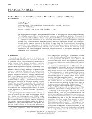
Absolute values of transport mean free path of light in non-absorbing ...
Absolute values of transport mean free path of light in non-absorbing ...
Absolute values of transport mean free path of light in non-absorbing ...

You also want an ePaper? Increase the reach of your titles
YUMPU automatically turns print PDFs into web optimized ePapers that Google loves.
260 J. GALVAN-MIYOSHI AND R. CASTILLO<br />
and<br />
where<br />
U(L) + CL<br />
C0 = 2 (1 + R)<br />
3 (1 − R)<br />
∂U<br />
(L) = 0, (11)<br />
∂z<br />
and CL = 2 (1 + Ref )<br />
3 (1 − Ref ) .<br />
Now, us<strong>in</strong>g Eqs. 8, 9, and J± expressions, we obta<strong>in</strong> the<br />
follow<strong>in</strong>g expressions for the fluxes:<br />
J−(0) = v Al<br />
2 C0l∗ �<br />
C0l∗ �<br />
l∗<br />
+ =<br />
2 3<br />
vAl<br />
(3C0 + 2) , (12)<br />
12C0<br />
and<br />
∗ vAll<br />
J+(L) = −<br />
12C0<br />
(C0 + α∗ ) (3CL + 2)<br />
(L + CLl∗ , (13)<br />
− zo)<br />
JT = |J−(0)| + |J+(L)| = vAl<br />
12C0<br />
�<br />
(3C0+2) (y+CL−α<br />
×<br />
∗ ) + (C0+α∗ ) (3CL+2)<br />
(y+CL−α∗ �<br />
, (14)<br />
)<br />
where y = L/l ∗ . F<strong>in</strong>ally, the static transmission coefficient<br />
is given by:<br />
T ∗ =<br />
(C0+α ∗ ) (3CL+2)<br />
(3C0+2) (y+CL−α ∗ ) + (C0+α ∗ ) (3CL+2)<br />
. (15)<br />
This f<strong>in</strong>al expression for T ∗ depends on α ∗ , L, and l ∗ as well<br />
as on R and on Ref through C0 and CL. As we shall show<br />
below, all variables <strong>in</strong>volved <strong>in</strong> this equation can be measured<br />
to obta<strong>in</strong> l ∗ . α ∗ can be obta<strong>in</strong>ed through a backscatter<strong>in</strong>g experiment,<br />
as described <strong>in</strong> Appendix C, while R is calculated<br />
with the procedure given by Kaplan et al. [10], us<strong>in</strong>g:<br />
l ∗ =<br />
This expression is our basic work<strong>in</strong>g equation to obta<strong>in</strong> l ∗<br />
from experimental data.<br />
2. Experimental section<br />
Materials. Polystyrene microspheres (Bangs Labs Inc,<br />
USA) <strong>of</strong> different diameters were used to prepare the water<br />
suspensions and also functioned as microsphere tracers <strong>in</strong> the<br />
DWS experiments to measure l ∗ . Glass cells were supplied<br />
by Hellma GmbH (Germany) and by Starna Cells Inc (USA)<br />
with different optical <strong>path</strong>s (2 mm to 4 mm) and different<br />
cross sections (3.0 × 4.2 mm and 2.8 × 3.7 mm). Water was<br />
milli-Q water (Nanopure-UV, USA; 18.3MΩ). Microspheres<br />
were added to water while stirr<strong>in</strong>g. Water suspensions were<br />
usually prepared with volume fractions < 0.04.<br />
Integrat<strong>in</strong>g sphere throughput. An <strong>in</strong>tegrat<strong>in</strong>g sphere<br />
(Oriel Newport, USA) was used to obta<strong>in</strong> l ∗ <strong>in</strong> the colloidal<br />
suspensions. Here, <strong>light</strong> detection was carried out by a photo<br />
multiplier tube (Hamamatsu Ltd, Japan) attached at the wall<br />
sphere. We obta<strong>in</strong>ed the <strong>in</strong>tegrat<strong>in</strong>g sphere throughput by<br />
where<br />
and<br />
R = 3C2 + 2C1<br />
. (16)<br />
3C2 − 2C1 + 2<br />
�<br />
C1 =<br />
π/2<br />
0<br />
�<br />
C2 =<br />
π/2<br />
0<br />
R(θ) cos θ s<strong>in</strong> θdθ<br />
R(θ) cos 2 θ s<strong>in</strong> θdθ.<br />
Ref can be calculated us<strong>in</strong>g the procedure presented <strong>in</strong> Appendix<br />
A, where the follow<strong>in</strong>g formula is obta<strong>in</strong>ed:<br />
with<br />
and<br />
D1 = −C1 + RspTwb<br />
D2 = C2 + RspTwb<br />
Ref = 3D2 − 2D1<br />
, (17)<br />
3D2 + 2D1 + 2<br />
�π<br />
π/2<br />
�π<br />
π/2<br />
Two(θ) cos θ s<strong>in</strong> θdθ,<br />
Two(θ) cos 2 θ s<strong>in</strong> θdθ.<br />
F<strong>in</strong>ally, solv<strong>in</strong>g for l ∗ <strong>in</strong> Eq. 15 and tak<strong>in</strong>g <strong>in</strong>to account the<br />
transmittance along the wall cells, we obta<strong>in</strong>:<br />
(3C0 + 2) TcdL<br />
(C0 + α ∗ ) (3CL + 2) (T1T0 − Tcd) + (CL − α ∗ ) (3C0 + 2) Tcd<br />
. (18)<br />
measur<strong>in</strong>g the <strong>in</strong>cident power, P 0 , at the front entrance port<br />
<strong>of</strong> the <strong>in</strong>tegrat<strong>in</strong>g sphere, and then ma<strong>in</strong>ta<strong>in</strong><strong>in</strong>g the laser <strong>light</strong><br />
power; constant the <strong>light</strong> power at the detection port <strong>of</strong> the<br />
<strong>in</strong>tegrat<strong>in</strong>g sphere, P 0 d<br />
Rev. Mex. Fís. 54 (3) (2008) 257–264<br />
, was measured. The throughput is<br />
b = P 0 d /P 0 . The <strong>in</strong>tegrat<strong>in</strong>g sphere is part <strong>of</strong> the <strong>in</strong>strument<br />
described below.<br />
Transport <strong>mean</strong> <strong>free</strong> <strong>path</strong>, l ∗ . We measured transmittance<br />
and reflectance for the suspensions under study with an<br />
<strong>in</strong>tegrat<strong>in</strong>g sphere as shown <strong>in</strong> Figs. 1 and 2, where a laser<br />
beam (λ = 514.5 nm) expanded and collimated with a 2<br />
mm p<strong>in</strong>hole was sent at normal <strong>in</strong>cidence <strong>in</strong>to the entrance<br />
port <strong>of</strong> the sphere. To measure l ∗ , we followed Eq. (18),<br />
where the total transmittance Tcd for a sample-cell system<br />
was measured, as described <strong>in</strong> Eq. (6), us<strong>in</strong>g the <strong>light</strong> power<br />
collected by the sphere detector <strong>in</strong> three different cases: when<br />
the sample is placed at the entrance port (transmission geom-<br />
), when it is placed at the reflection port (reflection<br />
etry, P T d<br />
geometry, P R d ), and when there is no sample on any port, P 0 d .