THE COAST ARTILLERY JOURNAL - Air Defense Artillery
THE COAST ARTILLERY JOURNAL - Air Defense Artillery
THE COAST ARTILLERY JOURNAL - Air Defense Artillery

You also want an ePaper? Increase the reach of your titles
YUMPU automatically turns print PDFs into web optimized ePapers that Google loves.
212 <strong>THE</strong> <strong>COAST</strong> <strong>ARTILLERY</strong> <strong>JOURNAL</strong><br />
4. Slant Ranges. a. As slant ranges from each observing station to the<br />
target were needed to convert mil deviations to yards, they were now plotted<br />
graphically, using the horizontal ranges just determined and the average altitude<br />
for that course as taken from the battery records. This was done on the<br />
plotting board previously described by setting a graduated T-square along one<br />
of the brass arms at the horizontal range 9 (Figure 5) and putting a pin into<br />
the board at the altitude 8 being used. The same arm was then swung over to<br />
this pin and the slant range 10 read off direct.<br />
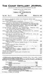
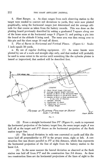
5. Plot of Bursts in Horizontal and Vertical Planes. (Figure 6.) Scale:<br />
1 inch equals 50 yards.<br />
a. By use of regular drafting equipment. (1) As some bursts were<br />
plotted by use of a scale and straight edge only, and that method will probably<br />
be used to some extent in the service until something like the xylonite plotter is<br />
issued or improvised, that method will be described first.<br />
LE6E/YO<br />
A - .Mean lCJrgel" Angle (2/00 mils.)<br />
8- A ven:>ge AngI' {35O /77//.sJ<br />
C r=o.stl/C\t7 0/ f3t./r~r //J J'he /7'or/zonJ'b/ ~<br />
O~ ~hc.v7 0/ LJvrs/ //7 I'M J*r//CQ/ flo/7e<br />
f- /tJ$lHbn oF Lk/r.sr In.P/one /H-rptt/lr:7/Cv/or<br />
ro /he Line 0/ Po.5///on<br />
F - CJonger YO/Un}(!.<br />
6- PrQ/ecr/C¥7 0/ fl/n/h<br />
,0/- P/??/ec/IGn of Co/u/J1n<br />
T- Tb>Yed lOrgei'<br />
/1£T/IOO OF PLOTT/NG P05/T/ON OF BURST<br />
.5c4k ../":50 )0/l:7"oS<br />
Flc. n<br />
(2) From a straight horizontal line S'T (Figure 61, made to represent<br />
the horizontal projection of the battery target line, the mean target angle A was<br />
laid off at the target and SliT drawn as the horizontal projection of the flank<br />
station target line.<br />
(3) The lateral deviation in mils was converted to yards and this distance<br />
laid off perpendicular to S'T in the proper sense, right or left. A construction<br />
line was drawn parallel to S'T at this distance, which thus represents<br />
the horizontal projection of the line of sight from the battery station to the<br />
burst L-3.<br />
(4) In the same manner the lateral deviation as observed at the flank<br />
station was laid off from SliT and the construction line S-8 drawn. As these<br />
two construction lines are the horizontal projections of the lines of sight to the