THE COAST ARTILLERY JOURNAL - Air Defense Artillery
THE COAST ARTILLERY JOURNAL - Air Defense Artillery
THE COAST ARTILLERY JOURNAL - Air Defense Artillery

You also want an ePaper? Increase the reach of your titles
YUMPU automatically turns print PDFs into web optimized ePapers that Google loves.
218 <strong>THE</strong> <strong>COAST</strong> <strong>ARTILLERY</strong> <strong>JOURNAL</strong><br />
marked. One of the other arms has a pointer (2) attached to it to read<br />
azimuths from the base plate. The outer rim of the base plate is graduated to<br />
ten mils.<br />
(3) The standard used for supporting the telescope is attached to the<br />
arms previously described. The telescope is attached to this standard by trunnions<br />
and an elevating hand screw mounted on these trunnions works through<br />
a worm screw to the elevating rack on the under side of the telescope.<br />
(4) The angular-height pointer is also attached to the trunnions and<br />
the scale to the telescope. The pointer is adjustable.<br />
(5) The telescope is a two-power instrument having both 10 and 25power<br />
magnification through two different eyepieces, either of which can be<br />
brought into use by a lever on the rear of the telescope.<br />
1< 2 • ------->I<br />
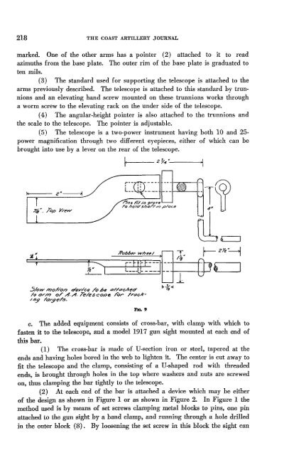
5/ow mOT/On aley/ce /0 be o/TdcheO'<br />
TOor/7? 0/ A.A. 7e/esco,oe ror rrdck-<br />
///.9 Torge/S.<br />
/7/JS njt i/J 9roY~<br />
To ho/a' shorr //7 'p/ac6'<br />
c. The added equipment consists of cross.bar, with clamp with which to<br />
fasten it to the telescope, and a model 1917 gun sight mounted at each end of<br />
this bar.<br />
(1) The cross-bar is made of U-section iron or steel, tapered at the<br />
ends and having holes bored in the web to lighten it. The center is cut away to<br />
fit the telescope and the clamp, consisting of a U-shaped rod with threaded<br />
ends, is brought through holes in the top where washers and nuts are screwed<br />
on, thus clamping the bar tightly to the telescope.<br />
(2) At each end of the bar is attached a device which may be either<br />
of the design as shown in Figure 1 or as shown in Figure 2. In Figure 1 the<br />
method used is by means of set screws clamping metal blocks to pins, one pin<br />
attached to the gun sight by a band clamp, and running through a hole drilled<br />
in the outer block (8). By loosening the set screw in this block the sight can