68-0262 - UV100E Ultraviolet Air Treatment System - NTsupply.com
68-0262 - UV100E Ultraviolet Air Treatment System - NTsupply.com
68-0262 - UV100E Ultraviolet Air Treatment System - NTsupply.com

Create successful ePaper yourself
Turn your PDF publications into a flip-book with our unique Google optimized e-Paper software.
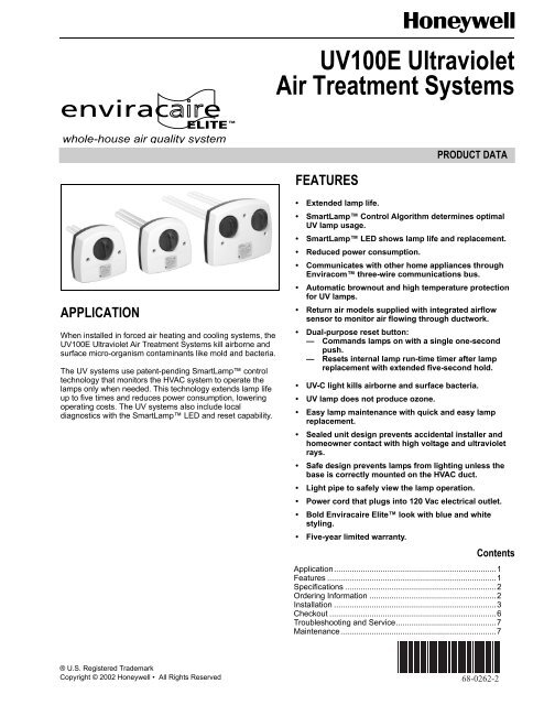
whole-house air quality system<br />
APPLICATION<br />
When installed in forced air heating and cooling systems, the<br />
<strong>UV100E</strong> <strong>Ultraviolet</strong> <strong>Air</strong> <strong>Treatment</strong> <strong>System</strong>s kill airborne and<br />
surface micro-organism contaminants like mold and bacteria.<br />
The UV systems use patent-pending SmartLamp control<br />
technology that monitors the HVAC system to operate the<br />
lamps only when needed. This technology extends lamp life<br />
up to five times and reduces power consumption, lowering<br />
operating costs. The UV systems also include local<br />
diagnostics with the SmartLamp LED and reset capability.<br />
® U.S. Registered Trademark<br />
Copyright © 2002 Honeywell • All Rights Reserved<br />
<strong>UV100E</strong> <strong>Ultraviolet</strong><br />
<strong>Air</strong> <strong>Treatment</strong> <strong>System</strong>s<br />
FEATURES<br />
PRODUCT DATA<br />
• Extended lamp life.<br />
• SmartLamp Control Algorithm determines optimal<br />
UV lamp usage.<br />
• SmartLamp LED shows lamp life and replacement.<br />
• Reduced power consumption.<br />
• Communicates with other home appliances through<br />
Envira<strong>com</strong> three-wire <strong>com</strong>munications bus.<br />
• Automatic brownout and high temperature protection<br />
for UV lamps.<br />
• Return air models supplied with integrated airflow<br />
sensor to monitor air flowing through ductwork.<br />
• Dual-purpose reset button:<br />
— Commands lamps on with a single one-second<br />
push.<br />
— Resets internal lamp run-time timer after lamp<br />
replacement with extended five-second hold.<br />
• UV-C light kills airborne and surface bacteria.<br />
• UV lamp does not produce ozone.<br />
• Easy lamp maintenance with quick and easy lamp<br />
replacement.<br />
• Sealed unit design prevents accidental installer and<br />
homeowner contact with high voltage and ultraviolet<br />
rays.<br />
• Safe design prevents lamps from lighting unless the<br />
base is correctly mounted on the HVAC duct.<br />
• Light pipe to safely view the lamp operation.<br />
• Power cord that plugs into 120 Vac electrical outlet.<br />
• Bold Enviracaire Elite look with blue and white<br />
styling.<br />
• Five-year limited warranty.<br />
Contents<br />
Application.........................................................................1<br />
Features ............................................................................1<br />
Specifications ....................................................................2<br />
Ordering Information .........................................................2<br />
Installation .........................................................................3<br />
Checkout ...........................................................................6<br />
Troubleshooting and Service.............................................7<br />
Maintenance......................................................................7<br />
<strong>68</strong>-<strong>0262</strong>-2
<strong>UV100E</strong> ULTRAVIOLET AIR TREATMENT SYSTEMS<br />
SPECIFICATIONS<br />
IMPORTANT<br />
This product is tested and calibrated under closely<br />
controlled conditions and some minor differences in<br />
performance can be expected if those conditions are<br />
changed. The specifications in this publication do not<br />
include normal manufacturing tolerances; therefore,<br />
an individual unit may not exactly match the listed<br />
specifications.<br />
TRADELINE® Models available:<br />
The <strong>UV100E</strong> <strong>Ultraviolet</strong> <strong>Air</strong> <strong>Treatment</strong> <strong>System</strong> is available in<br />
three models: a single-lamp, moderate-efficiency return air<br />
unit; a dual-lamp, high-efficiency return air unit; and an air<br />
conditioner coil irradiation unit.<br />
• <strong>UV100E</strong> single-lamp and dual-lamp return air units are<br />
mounted in the return air duct of an HVAC system. The<br />
units have high-efficiency performance against airborne<br />
bacteria in return air applications.<br />
— Without Envira<strong>com</strong> hooked up: monitors air flowing<br />
through ductwork using supplied airflow sensor<br />
mounted to backside of unit. Operates lamps when air<br />
is flowing (120 fpm minimum), leaving lamps on for 40<br />
minutes after airflow stops. If airflow resumes during<br />
the 40 minutes, the timer resets to 40 minutes. When<br />
no airflow is detected for 40 minutes, the lamps turn off<br />
until the next occurrence of airflow.<br />
— With Envira<strong>com</strong> hooked up: monitors thermostat load<br />
information instead of using airflow sensor to operate<br />
on and off.<br />
• <strong>UV100E</strong> coil irradiation unit is mounted in the supply-side<br />
air duct or downstream or upstream from air conditioner<br />
evaporator coils in HVAC system. It reduces mold growth<br />
and spores on duct surfaces, coils and drip pans.<br />
— Does not use an airflow sensor.<br />
— Without Envira<strong>com</strong> hooked up: operates steady on/off<br />
cycle: lamp operates three hours on, three hours off<br />
for a total two-year life cycle.<br />
— With Envira<strong>com</strong> hooked up: after initial three hours run<br />
time, operates three hours on and three hours off during<br />
times when the evaporator A-coil may be exposed<br />
to moisture, including when the control sees a cooling<br />
call and for 30 days after the last cooling occurred.<br />
This operation extends the lamp life beyond two years.<br />
ORDERING INFORMATION<br />
When purchasing replacement and modernization products from your TRADELINE® wholesaler or distributor, refer to the<br />
TRADELINE® Catalog or price sheets for <strong>com</strong>plete ordering number.<br />
If you have additional questions, need further information, or would like to <strong>com</strong>ment on our products or services, please write:<br />
1. Your local Home and Building Control Sales Office (check white pages of your phone directory).<br />
2. Home and Building Control Customer Relations<br />
Honeywell, 1885 Douglas Drive North<br />
Minneapolis, Minnesota 55422-4386<br />
In Canada—Honeywell Limited/Honeywell Limitée, 35 Dynamic Drive, Scarborough, Ontario M1V 4Z9.<br />
International Sales and Service Offices in all principal cities of the world. Manufacturing in Australia, Canada, Finland, France,<br />
Germany, Japan, Mexico, Netherlands, Spain, Taiwan, United Kingdom, U.S.A.<br />
<strong>68</strong>-<strong>0262</strong>-2 2<br />
Efficiencies:<br />
• <strong>UV100E</strong> Coil Irradiation unit: Kills up to 99.9% of mold on<br />
system cooling coils.<br />
— Test performed in a test duct showed reduction in colony-forming<br />
aspergillus niger mold spores when surface<br />
was irradiated at a distance of 18 in. for three<br />
hours in still air, using new lamps.<br />
• UV100A Dual-Lamp Return unit: Kills up to 87% of<br />
airborne bacterial passing by the system.<br />
— Test showed single-pass kill-rate of serratia marcescens<br />
bacteria in a clean metal 12 in. x 25 in. duct at<br />
an airflow rate of 2000 cfm using new lamps.<br />
• UV100A Single-Lamp Return unit: Kills up to 70% of<br />
airborne bacteria passing by the system.<br />
— Test showed single-pass kill-rate of serratia marcescens<br />
bacteria in a clean metal 12 in. x 25 in. duct at<br />
an airflow rate of 2000 cfm using new lamps.<br />
Envira<strong>com</strong> Communications Capabilities:<br />
• Communicates with homeowner through three-wire<br />
<strong>com</strong>munication bus using 24 Vac thermostat connections.<br />
— Hooked up to single-lamp and dual-lamp return air<br />
models: uses thermostat load information instead of<br />
airflow sensor.<br />
— Hooked up to coil irradiation mode: uses thermostat<br />
load information to operate during times evaporator Acoil<br />
may be exposed to moisture to extend lamp life<br />
beyond two years.<br />
• Sends messages to <strong>com</strong>municate reset and receives<br />
remote reset, when available.<br />
— Lamp change indication cannot be reset by cycling<br />
power.<br />
— When Envira<strong>com</strong> is transmitting messages, shows<br />
flashing green Envira<strong>com</strong> LED on bottom of unit.<br />
• Other messages include percent of lamp remaining,<br />
internal faults, and lamps energized.<br />
— Control calculates percent of lamp run time/starts<br />
remaining and sends out this information through an<br />
Envira<strong>com</strong> message.<br />
— When Envira<strong>com</strong> is transceiving messages, shows<br />
solid green Envira<strong>com</strong> LED on bottom of unit.<br />
Approvals:<br />
Underwriters Laboratories: File no. E212213.<br />
The health aspects associated with the use of this product and<br />
its ability to aid in disinfection of environmental air have not<br />
been investigated by UL.
Electrical Ratings:<br />
Voltage Rating: 120 Vac, 60 Hz.<br />
Current and Power Ratings:<br />
Input Current Lamp Wattage<br />
Model<br />
(A)<br />
(W)<br />
Coil Irradiation 0.74 36<br />
Single-Lamp Return 0.46 18<br />
Dual-Lamp Return 0.62 36 each lamp<br />
Temperature Ratings:<br />
Ambient Temperature Range: 30°F to 104°F (-2°C to 40°C).<br />
Lamp Temperature Range (In Moving <strong>Air</strong>): 30°F to 140°F<br />
(-2°C to 60°C).<br />
Relative Humidity:<br />
Up to 95% rh, non-condensing.<br />
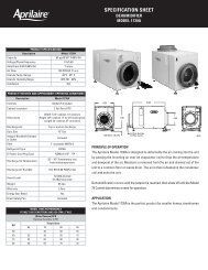
Dimensions:<br />
See Fig. 2.<br />
INSTALLATION<br />
When Installing this Product…<br />
1. Read these instructions carefully. Failure to follow them<br />
could damage the product or cause a hazardous<br />
condition.<br />
2. Check the rating given in the instructions and on the<br />
product to make sure the product is suitable for your<br />
application.<br />
3. Installer must be a trained, experienced service<br />
technician.<br />
4. After installation is <strong>com</strong>plete, check out product<br />
operation as provided in these instructions.<br />
CAUTION<br />
Personal Injury Hazard.<br />
Power supply can cause electrical shock.<br />
Disconnect power supply before beginning installation.<br />
Do not open base unit or lamp knob; there are no<br />
user-serviceable <strong>com</strong>ponents inside.<br />
WARNING<br />
UV Light Hazard.<br />
Harmful to bare skin and eyes.<br />
Can cause temporary or permanent loss of vision.<br />
Never look at the lamps while illuminated.<br />
Only view illumination by way of the light pipe indicator<br />
on the lamp knob.<br />
To prevent exposure to ultraviolet light, disconnect<br />
power to the ultraviolet air treatment system before<br />
servicing any part of the heating/air conditioning<br />
system.<br />
Do not mount device in location that allows ultraviolet<br />
light to be seen after installation.<br />
Do not attempt to bypass the duct mount switch.<br />
<strong>UV100E</strong> ULTRAVIOLET AIR TREATMENT SYSTEMS<br />
Selecting Mounting Location<br />
CAUTION<br />
Equipment Damage Hazard.<br />
<strong>Ultraviolet</strong> light can cause color shift or structural<br />
degradation of plastic HVAC materials.<br />
Select mounting location that prevents exposure to<br />
plastic <strong>com</strong>ponents with unknown resistance to<br />
ultraviolet light. Three-feet minimum is re<strong>com</strong>mended<br />
between ultraviolet lamps and plastic-fabricated<br />
devices (such as humidifiers and non-fiberglass media<br />
filters).<br />
IMPORTANT<br />
If mounting options are limited, protect plastic or rubber<br />
materials listed in CAUTION with ultravioletresistant<br />
material such as aluminum foil duct tape.<br />
NOTE: When the installer is uncertain about whether the<br />
drip pan in the installation can tolerate UV exposure,<br />
consult the UV exposure white paper, form no. 50-<br />
8788, at hbctechlit.<strong>com</strong> Web site .<br />
1. Choose a location that is readily accessible for regular<br />
inspection and cleaning. Fig. 1 shows possible mounting<br />
locations.<br />
2. Allow clearance in front of the device for removing the<br />
lamp assemblies. Fig. 2 shows lamp assembly lengths.<br />
3. Be sure depth can ac<strong>com</strong>modate full length of UV lamp<br />
for your model as shown in Fig. 2.<br />
4. Be sure duct mounting location is 8 in. wide minimum.<br />
5. Be sure 120 Vac electrical outlet is within range of unit<br />
to plug in the power cord.<br />
6. Select single-lamp and dual-lamp unit location on HVAC<br />
return air duct that is easily accessible with a flat mounting<br />
surface. Select coil irradiation unit location on HVAC<br />
supply air duct that is easily accessible with a flat<br />
mounting surface; locate the unit so the lamp can surround<br />
the evaporator coil and drip pan with ultraviolet<br />
light.<br />
7. Mount to allow correct operation:<br />
a. Do not mount upside down.<br />
b. Do not mount with lalmps facing up.<br />
CAUTION<br />
Sharp Edges Hazard.<br />
Can cause personal injury.<br />
Be careful when inserting ultraviolet device into the<br />
sheet metal cutout.<br />
Wear protective gloves when working near sheet<br />
metal.<br />
3 <strong>68</strong>-<strong>0262</strong>-2
<strong>UV100E</strong> ULTRAVIOLET AIR TREATMENT SYSTEMS<br />
Duct Mounting<br />
Use the following instructions to mount the UV air treatment<br />
system on the air duct of an HVAC system:<br />
1. Disconnect power to the HVAC system before installing<br />
the <strong>Ultraviolet</strong> <strong>Air</strong> <strong>Treatment</strong> <strong>System</strong>.<br />
2. Select the appropriate template for your model (see<br />
Fig. 5-7).<br />
3. Place the appropriate template for your model on the<br />
duct surface, centering the lamp hole(s) on the duct.<br />
4. Mark the location on the duct for 2 in. diameter lamp<br />
hole(s), unit mounting-screw pilot holes, and when<br />
installing a return air model, the 1-1/2 in. airflow sensor<br />
hole.<br />
SINGLE-LAMP<br />
AND DUAL-LAMP<br />
UNIT LOCATION<br />
CONDITIONED AIR<br />
TO ROOM<br />
COIL IRRADIATION<br />
UNIT LOCATION<br />
RETURN<br />
AIR<br />
HIGH EFFICIENCY<br />
AIR CLEANER<br />
CONDENSATE<br />
DRAIN<br />
HEAT<br />
EXCHANGER<br />
<strong>68</strong>-<strong>0262</strong>-2 4<br />
ELECTRONIC AIR CLEANER<br />
5. Cut 2 in. lamp hole(s) and 1-1/2 in. airflow sensor hole<br />
in the duct. Remove any burrs. Note that the airflow<br />
sensor protrudes out of backside of device. Be careful<br />
to avoid scratching or damaging the airflow sensor.<br />
6. Use a 3/32- in. drill for pilot holes for mounting screws.<br />
7. Be sure duct surface is flat after all holes are drilled.<br />
8. Position entire base unit on duct. Be sure lamp and airflow<br />
sensor holes in duct align with unit holes. Be careful<br />
to avoid scratching or damaging the airflow sensor.<br />
9. Install unit into duct using three (or two, depending on<br />
model) no.10, 2 in. Phillips head sheet metal mounting<br />
screws provided. (A spare screw is provided for threescrew<br />
model.)<br />
10. Tighten screws to 12 to 14 in.-lb so space between case<br />
and duct is sealed.<br />
REMOTE CONDENSER<br />
SECTION (HIGH SIDE)<br />
REFRIGERANT<br />
PIPING<br />
FURNACE<br />
Fig. 1. Possible mounting locations for <strong>Ultraviolet</strong> <strong>Air</strong> <strong>Treatment</strong> <strong>System</strong>s.<br />
CONDENSER<br />
COOLING AIR<br />
M13529A
2-1/4 (57)<br />
3-1/2 (89)<br />
8-1/2<br />
(216)<br />
7 (178)<br />
2-1/4 (57)<br />
3-1/2 (89)<br />
7 (178)<br />
4-1/2 (114)<br />
3-1/2 (89)<br />
3-1/2 (89)<br />
5 (127)<br />
10 (254)<br />
4-1/2 (114)<br />
3-1/2<br />
(89)<br />
1<br />
(25)<br />
5 (127)<br />
7<br />
(178)<br />
7 (178)<br />
3-1/2<br />
(89)<br />
1<br />
(25)<br />
7<br />
(178)<br />
4 (102)<br />
2-3/16<br />
(56)<br />
3-1/4<br />
(83)<br />
Fig. 2. <strong>Ultraviolet</strong> AIr <strong>Treatment</strong> <strong>System</strong> dimensions in in. (mm).<br />
<strong>UV100E</strong> ULTRAVIOLET AIR TREATMENT SYSTEMS<br />
COIL IRRADIATION<br />
4 (102) 14-7/8 (379)<br />
1/2 (12)<br />
7-7/16 (188)<br />
M20190<br />
SINGLE-LAMP RETURN<br />
4 (102)<br />
DUAL-LAMP<br />
RETURN<br />
1/2 (12)<br />
14-7/8 (379)<br />
M20192<br />
M20191<br />
5 <strong>68</strong>-<strong>0262</strong>-2
<strong>UV100E</strong> ULTRAVIOLET AIR TREATMENT SYSTEMS<br />
CAUTION<br />
Breakable Glass Hazard.<br />
Can cause personal injury.<br />
Be careful when inserting lamps(s) into lamp base.<br />
Wear protective gloves when handling lamp(s).<br />
MERCURY NOTICE<br />
This device contains mercury in the sealed ultraviolet<br />
lamp(s). Do not place your used lamp(s) in the trash.<br />
Dispose of properly.<br />
Broken Lamp Cleanup.<br />
Do not use a household vacuum.<br />
Sweep debris into a plastic bag and dispose of<br />
properly.<br />
Contact your local waste management authority for<br />
instructions regarding recycling and the proper<br />
disposal of old lamp(s).<br />
11. Insert the lamp into the base unit with the light-pipe indicator<br />
at the eleven o’clock position (left of the raised<br />
button on the unit cover). Do not touch the lamp surface<br />
with your hands.<br />
12. Continue lightly pushing in on the lamp while rotating it<br />
slowly counterclockwise. This should cause the lamp to<br />
drop into the bottom of the lamp well.<br />
13. Rotate the lamp clockwise until it snaps into place with<br />
the light pipe indicator aligned with the raised button on<br />
the unit cover.<br />
WARNING<br />
UV Light Hazard.<br />
Harmful to bare skin and eyes.<br />
Can cause temporary or permanent loss of vision.<br />
Never look at the lamps while illuminated.<br />
Only view illumination by way of the light pipe indicator<br />
located on the lamp knob.<br />
To prevent exposure to ultraviolet light, disconnect<br />
power to the ultraviolet air treatment system before<br />
servicing any part of the heating/air conditioning<br />
system.<br />
NOTE: If you desire to <strong>com</strong>municate with other appliances<br />
using your Envira<strong>com</strong> <strong>com</strong>munication bus, go on to<br />
step 14; if not, go directly to step 15.<br />
14. Hook up corresponding appliance wires to the Envira<strong>com</strong><br />
<strong>com</strong>munication bus located on the bottom of the<br />
UV device base. Be sure to loop wire of other<br />
<strong>68</strong>-<strong>0262</strong>-2 6<br />
Envira<strong>com</strong> appliances or Envira<strong>com</strong> <strong>com</strong>mon node<br />
around the UV base Envira<strong>com</strong> screw terminals 1, 2<br />
and 3. See Fig. 3.<br />
15. Plug the cord into the nearby 120 Vac electrical outlet.<br />
RESET<br />
Fig. 3. Looping Envira<strong>com</strong> appliance or <strong>com</strong>mon node<br />
wire around UV Envira<strong>com</strong> base screw terminals.<br />
16. Wait ten minutes for the airflow sensor to calibrate. During<br />
this time, the furnace fan must remain Off.<br />
NOTE: Failure to wait ten minutes for the airflow sensor to<br />
calibrate before powering the furance causes the airflow<br />
sensor to incorrectly calibrate and the device to<br />
incorrectly function. If this occurs, remove power to<br />
the furnace or turn off the system and fan, wait ten<br />
minutes, and then resume normal furnace operation.<br />
17. Reconnect the power to the HVAC system.<br />
18. Choose a location on the adjacent HVAC equipment for<br />
the HVAC maintenance label included in the air<br />
treatment system packing box. Choose a location that a<br />
future installer can easily see during any future HVAC<br />
maintenance or repair.<br />
19. Adhere the HVAC maintenance label to the HVAC<br />
equipment (selected in step 17) such as the furnace, air<br />
cleaner or humidifier.<br />
CHECKOUT<br />
1<br />
2 3 M20242<br />
The installer should verify that the ultraviolet lamp(s) are<br />
operating only by viewing the light pipe indicator on the lamp<br />
knob. Do not attempt to look directly into the duct to see the<br />
illuminated ultraviolet lamps.<br />
The installer should orient the homeowner to the unit by<br />
showing them the blue glow of the light pipe indicator and<br />
discussing how to determine when the unit is functioning<br />
properly without looking directly into the duct to see the<br />
illuminated ultraviolet lamps. The installer should also<br />
emphasize the hot surface and electrical shock safety<br />
warnings.
The installer should show the homeowner the LED on the<br />
front of the UV system and explain operation as follows:<br />
LED Status Indicates Homeowner Action<br />
Off 100 to 11% lamp life a<br />
remaining<br />
Nothing<br />
Flashing 10 to 1% lamp life a<br />
remaining<br />
Purchases lamp(s)<br />
Solid 0% lamp lifea remaining Replaces lamp(s)<br />
a Lamp life means emitting adequate amount of UV-C energy<br />
to maintain an effective kill rate. At 0% lamp life remaining,<br />
the lamps continue to operate until catastrophic lamp failure<br />
(lamp burns out) but the kill rate be<strong>com</strong>es rapidly negligible.<br />
Installer should also orient the homeowner to the reset button<br />
on the bottom of the UV system that, when pressed briefly for<br />
one second, can be used to <strong>com</strong>mand lamps on for the<br />
minimum run time of 40 minutes (return) or three hours (coil),<br />
depending on unit type. And that when a new lamp is<br />
installed, the homeowner must hold the reset button for five<br />
seconds to reset the internal timers. Cycling power does not<br />
reset internal timers.<br />
When using the Envira<strong>com</strong> <strong>com</strong>munication bus to <strong>com</strong>municate<br />
with other appliances, the installer should orient the<br />
homeowner to the Envira<strong>com</strong> LED and three screw terminals.<br />
The Envira<strong>com</strong> LED flashes when transmitting and lights<br />
solidly when there is a fault.<br />
The installer should also explain the extended-lamp life for the<br />
coil irradiation model. For the single-lamp and dual-lamp<br />
return air models, the installer should orient the homeowner to<br />
the alternate method of using the UV device to monitor the<br />
thermostat load information to turn lamps off and on instead of<br />
using the air flow sensor to control lamp operation and that it<br />
<strong>com</strong>municates the percent remaining lamp life.<br />
The installer should leave the Owner’s Guide and Product<br />
Data with the homeowner and review the lamp cleaning and<br />
lamp replacement procedures. A Lamp Cleaning Schedule is<br />
included in the Owner’s Guide to help the homeowner set up<br />
and track a regular cleaning schedule.<br />
TROUBLESHOOTING AND SERVICE<br />
The <strong>Ultraviolet</strong> <strong>Air</strong> <strong>Treatment</strong> <strong>System</strong> has no field-serviceable<br />
parts. Lamp cleaning is re<strong>com</strong>mended as routine<br />
maintenance four times a year or every three months<br />
(quarterly). Lamp replacement is required when the LED on<br />
the front of the UV system is lighted solidly. See the Owner’s<br />
Guide for detailed procedural information.<br />
If units with an airflow sensor (<strong>UV100E</strong>1043 and<br />
<strong>UV100E</strong>2009), incorrectly identify airflow, the airflow sensor<br />
may be calibrated incorrectly. To recalibrate the sensor,<br />
remove power to the furnace or turn off the system and fan,<br />
<strong>UV100E</strong> ULTRAVIOLET AIR TREATMENT SYSTEMS<br />
wait ten minutes, and then resume normal furnace operation.<br />
Even if the lamp(s) fails to turn off, the sensor was<br />
recalibrated during this operation.<br />
If the internal temperature exceeds the ballast hightemperature<br />
limit, the control continues to retry every three<br />
hours until the temperature is low enough to run correctly. An<br />
Envira<strong>com</strong> fault message (when connected) sent after 72<br />
hours. If reset is pushed during this fault, the control tries to<br />
restart but cannot start until temperature returns to normal.<br />
If the unit lamp(s) burns out, experiences low supply voltage<br />
(brownout) or has an internal catastrophic failure, the control<br />
continues to retry once every hour until the problem is<br />
corrected. An Envira<strong>com</strong> fault message (when connected) is<br />
sent after 24 hours. If reset is pushed during this fault, the<br />
control tries to restart but cannot start until fault is corrected.<br />
To determine if a lamp is burned out or other problem exists,<br />
press the reset button briefly (one second). The lamp(s)<br />
should <strong>com</strong>e on (as indicated by the illuminating light pipe).<br />
Hold reset button longer only when replacing the lamp.<br />
MAINTENANCE<br />
How You Can Maintain Your <strong>Ultraviolet</strong><br />
<strong>Air</strong> <strong>Treatment</strong> <strong>System</strong><br />
You should regularly clean your ultraviolet lamps to maintain<br />
your air treatment system. And when the LED on the front of<br />
the UV system is lighted solidly, you must remember to<br />
replace your ultraviolet lamps.<br />
CAUTION<br />
Personal Injury Hazard.<br />
Power supply can cause electrical shock.<br />
Disconnect power supply before cleaning or replacing<br />
ultraviolet lamp(s).<br />
Do not open base unit or lamp knob; there are no<br />
user-serviceable <strong>com</strong>ponents inside.<br />
CAUTION<br />
Breakable Glass Hazard.<br />
Can cause personal injury.<br />
Be careful when inserting lamp(s) into lamp base.<br />
Wear protective gloves when handling lamp(s).<br />
Cleaning Your Lamps Every Three Months<br />
(Quarterly)<br />
Lamp cleaning is re<strong>com</strong>mended as routine maintenance four<br />
times a year or every three months (quarterly). Use the<br />
<strong>Ultraviolet</strong> Lamp Cleaning Reminder Schedule, Fig. 4, to help<br />
you establish and track your regular cleaning schedule.<br />
7 <strong>68</strong>-<strong>0262</strong>-2
<strong>UV100E</strong> ULTRAVIOLET AIR TREATMENT SYSTEMS<br />
YEAR<br />
MERCURY NOTICE<br />
This device contains mercury (less than 5 mg) in the<br />
sealed ultraviolet lamp(s). Do not place your used<br />
lamp(s) in the trash. Dispose of properly.<br />
Broken Lamp Cleanup.<br />
Do not use a household vacuum.<br />
Sweep debris into a plastic bag and dispose of<br />
properly.<br />
Contact your local waste management authority for<br />
instructions regarding recycling and the proper<br />
disposal of old lamp(s).<br />
CAUTION<br />
UV Lamp Burn Hazard.<br />
Harmful to bare skin.<br />
Can cause severe burns.<br />
Disconnect power 15 minutes before removing the<br />
ultraviolet lamp(s)<br />
UV LAMP CLEANING REMINDER SCHEDULE<br />
INSTALLATION DATE: (month)<br />
, (year)<br />
J F M A M J J A S O N D<br />
M13516<br />
Fig. 4. <strong>Ultraviolet</strong> lamp cleaning reminder schedule.<br />
To clean your lamps:<br />
1. Disconnect the power to your HVAC system.<br />
2. Unplug your ultraviolet air treatment system cord from<br />
the electrical outlet and allow the lamps to cool for at<br />
least 15 minutes.<br />
3. Rotate your lamp knob counterclockwise and gently pull<br />
the lamp knob to remove the lamp(s).<br />
4. Holding only the lamp knob, wipe the lamp glass using a<br />
soft cloth with window cleaner applied to it. Do not<br />
touch the lamp surface with your hands. Use only<br />
the cloth.<br />
5. To ensure that the light pipe indicator continues to function,<br />
use a moistened cotton swab to gently remove any<br />
dust that may have collected between the light indicator<br />
on the base and the black lamp base.<br />
6. Wipe your lamps with a clean, dry cloth.<br />
7. Put your clean lamps back into the unit base by following<br />
Replacing Your Lamps section steps 5, 6, and 7.<br />
<strong>68</strong>-<strong>0262</strong>-2 8<br />
WARNING<br />
UV Light Hazard.<br />
Harmful to bare skin and eyes.<br />
Can cause temporary or permanent loss of vision.<br />
Never look at the lamps while illuminated.<br />
Only view illumination by way of the light pipe indicator<br />
located on the lamp knob.<br />
To prevent exposure to ultraviolet light, disconnect<br />
power to ultraviolet air treatment system before<br />
servicing any part of heating/air conditioning system.<br />
8. Plug the cord into the nearby 120 Vac electrical outlet.<br />
9. Verify that ultraviolet lamp(s) are operating only by viewing<br />
through light pipe indicator on lamp knob. Never<br />
look directly at your lamps while illuminated.<br />
10. Reconnect the power to your HVAC system.<br />
CAUTION<br />
UV Lamp Burn Hazard.<br />
Harmful to bare skin.<br />
Can cause severe burns.<br />
Disconnect power 15 minutes before removing the<br />
ultraviolet lamp(s).<br />
Replacing Your Lamps<br />
Replacement of your lamps is required when LED on front of<br />
the unit is lighted solidly.<br />
NOTE: LED blinking slowly, one second on and one second<br />
off, indicates that ten percent or less of lamp life<br />
remains and homeowner must order new lamp(s).<br />
IMPORTANT<br />
Anytime the reset button is pushed, the lamp(s)<br />
should <strong>com</strong>e on (as indicated by the illuminating light<br />
pipe). To determine if a lamp is burned out or other<br />
problem exists, press the reset button briefly (one<br />
second). Hold reset button longer (five seconds)<br />
only when replacing lamp.<br />
To replace your lamps:<br />
1. Select and obtain the correct replacement lamp for your<br />
unit. See Parts List.<br />
2. Disconnect the power to your HVAC system.<br />
3. Unplug your ultraviolet air treatment system cord from<br />
the electrical outlet and allow the lamps to cool for at<br />
least 15 minutes.<br />
4. Rotate the lamp knob counterclockwise and gently pull<br />
the lamp knob to remove the lamp(s).<br />
5. Insert the lamp into the base unit with the light pipe indicator<br />
at the eleven o’clock position (left of the raised<br />
button on the unit cover). Do not touch the lamp surface<br />
with your hands.<br />
6. Continue lightly pushing in on lamp while rotating it<br />
slowly counterclockwise until lamp to drops into bottom<br />
of lamp well.<br />
7. Rotate lamp clockwise until it snaps into place with light<br />
pipe indicator aligned with raised button on unit cover.
WARNING<br />
UV Light Hazard.<br />
Harmful to bare skin and eyes.<br />
Can cause temporary or permanent loss of vision.<br />
Never look at the lamps while illuminated.<br />
Only view illumination by way of the light pipe indicator<br />
located on the lamp knob.<br />
To prevent exposure to ultraviolet light, disconnect<br />
power to ultraviolet air treatment system before<br />
servicing any part of heating/air conditioning system.<br />
8. Plug your ultraviolet air treatment system cord into the<br />
nearby 120 Vac electrical outlet.<br />
9. Verify that your ultraviolet lamp(s) are operating only by<br />
viewing through light indicator on lamp knob. Never look<br />
directly at your lamp(s) while illuminated.<br />
10. Reconnect the power to your HVAC system.<br />
11. Press and hold the reset button on the bottom of the<br />
device for five seconds to reset the internal timers.<br />
<strong>UV100E</strong> ULTRAVIOLET AIR TREATMENT SYSTEMS<br />
<strong>UV100E</strong> Parts List<br />
Table 1. Replacing UV Lamps.<br />
Unit Description<br />
<strong>UV100E</strong>1043 Single-Lamp<br />
Return <strong>Air</strong> Unit<br />
(left photo)<br />
<strong>UV100E</strong>3007 Coil Irradiation<br />
Unit (center photo)<br />
<strong>UV100E</strong>2009 Dual-Lamp<br />
Return <strong>Air</strong> Unit<br />
(right photo)<br />
Replacement<br />
Lamp Wattage<br />
UC100E1006 18W<br />
UC100E1030 36W<br />
UC100E1014<br />
(twin pack)<br />
(two lamps<br />
provided)<br />
36W<br />
each<br />
lamp<br />
9 <strong>68</strong>-<strong>0262</strong>-2
<strong>UV100E</strong> ULTRAVIOLET AIR TREATMENT SYSTEMS<br />
CENTER OF 2 IN. (51 MM)<br />
HOLE FOR LAMP<br />
1-1/2 IN. (38)<br />
HOLE FOR<br />
AIRFLOW SENSOR<br />
CENTER OF AIRFLOW<br />
SENSOR HOLE<br />
Fig. 5. Single-Lamp Return <strong>Air</strong> <strong>Ultraviolet</strong> <strong>Air</strong> <strong>Treatment</strong> <strong>System</strong> template.<br />
(Dual-Lamp Return <strong>Air</strong> <strong>Ultraviolet</strong> <strong>Air</strong> <strong>Treatment</strong> <strong>System</strong> template is located on next page.)<br />
Fig. 6. Dual-Lamp Return <strong>Air</strong> <strong>Ultraviolet</strong> <strong>Air</strong> <strong>Treatment</strong> <strong>System</strong> template.<br />
<strong>68</strong>-<strong>0262</strong>-2 10<br />
ALIGN EITHER OF THESE LINES<br />
AS CLOSE AS POSSIBLE TO<br />
DUCT CENTER LINE<br />
3/32 IN. (3 MM) PILOT HOLES<br />
FOR MOUNTING SCREWS<br />
INSTALLATION TEMPLATE FOR SINGLE-LAMP RETURN UNIT.<br />
M20194
3/32 IN. (3 MM) PILOT HOLES<br />
FOR MOUNTING SCREWS<br />
ALIGN EITHER OF THESE LINES<br />
AS CLOSE AS POSSIBLE TO<br />
DUCT CENTER LINE<br />
CENTERS OF 2 IN. (51 MM)<br />
HOLES FOR LAMP<br />
<strong>UV100E</strong> ULTRAVIOLET AIR TREATMENT SYSTEMS<br />
1-1/2 IN. (38)<br />
HOLE FOR<br />
AIRFLOW SENSOR<br />
CENTER OF AIRFLOW<br />
SENSOR HOLE<br />
INSTALLATION TEMPLATE<br />
FOR DUAL-LAMP RETURN UNIT<br />
11 <strong>68</strong>-<strong>0262</strong>-2<br />
3/32 IN. (3 MM) PILOT HOLES<br />
FOR MOUNTING SCREWS<br />
M20195
<strong>UV100E</strong> ULTRAVIOLET AIR TREATMENT SYSTEMS<br />
CENTER OF 2 IN. (51 MM)<br />
HOLE FOR LAMP<br />
3/32 IN. (3 MM) PILOT HOLES<br />
FOR MOUNTING SCREWS<br />
Fig. 7. Coil Irradiation <strong>Ultraviolet</strong> AIr <strong>Treatment</strong> <strong>System</strong> template.<br />
Automation and Control Solutions<br />
Honeywell Honeywell Limited-Honeywell Limitée<br />
1985 Douglas Drive North 35 Dynamic Drive<br />
Golden Valley, MN 55422 Scarborough, Ontario<br />
M1V 4Z9<br />
INSTALLATION TEMPLATE FOR COIL IRRADIATION UNIT.<br />
ALIGN EITHER OF THESE LINES<br />
AS CLOSE AS POSSIBLE TO<br />
DUCT CENTER LINE<br />
Printed in U.S.A. on recycled<br />
<strong>68</strong>-<strong>0262</strong>-2 G.H. Rev. 7-02 paper containing at least 10%<br />
post-consumer paper fibers.<br />
www.honeywell.<strong>com</strong>/yourhome<br />
M20193