Operating Instructions FR(MU)1000 - ziehl.de
Operating Instructions FR(MU)1000 - ziehl.de
Operating Instructions FR(MU)1000 - ziehl.de

You also want an ePaper? Increase the reach of your titles
YUMPU automatically turns print PDFs into web optimized ePapers that Google loves.
Temperature Relays and MINIKA®, Mains Monitoring, Digital Panelmeters MINIPAN®, Switching Relays and Controls<br />
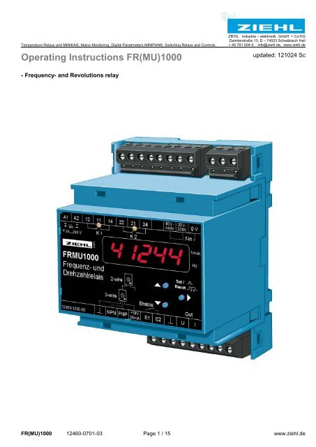
<strong>Operating</strong> <strong>Instructions</strong> <strong>FR</strong>(<strong>MU</strong>)<strong>1000</strong><br />
- Frequency- and Revolutions relay<br />
ZIEHL industrie – elektronik GmbH + Co KG<br />
Daimlerstraße 13, D – 74523 Schwäbisch Hall<br />
+ 49 791 504-0, info@<strong>ziehl</strong>.<strong>de</strong>, www.<strong>ziehl</strong>.<strong>de</strong><br />
updated: 121024 Sc<br />
<strong>FR</strong>(<strong>MU</strong>)<strong>1000</strong> 12460-0701-03 Page 1 / 15 www.<strong>ziehl</strong>.<strong>de</strong>
Table of contents<br />
1 Application and short <strong>de</strong>scription ......................................................................................................... 3<br />
2 Overview of functions ............................................................................................................................ 3<br />
3 Connecting diagram ............................................................................................................................... 4<br />
4 Display and operation parts ................................................................................................................... 4<br />
5 Programs................................................................................................................................................. 4<br />
6 Important Information ............................................................................................................................ 5<br />
7 Installation .............................................................................................................................................. 6<br />
8 Putting into operation ............................................................................................................................ 6<br />
8.1 Display mo<strong>de</strong> ................................................................................................................................. 6<br />
8.2 Menu mo<strong>de</strong> (Decimal point behind the last digit ON) ..................................................................... 6<br />
8.3 Parameter setting mo<strong>de</strong> (Decimal point behind the last digit BLINKS) ........................................... 6<br />
8.4 Indications of the digital display ..................................................................................................... 9<br />
9 Operation .............................................................................................................................................. 10<br />
9.1 Program 1: Pr1 / Speed Monitoring ............................................................................................. 10<br />
9.2 Program 2: Pr2 / Frequency Monitoring ....................................................................................... 11<br />
10 Factory setting ...................................................................................................................................... 12<br />
11 Error search and measures ................................................................................................................. 12<br />
12 Technical data ...................................................................................................................................... 13<br />
13 Type V4 ................................................................................................................................................. 15<br />
<strong>FR</strong>(<strong>MU</strong>)<strong>1000</strong> 12460-0701-03 Page 2 / 15 www.<strong>ziehl</strong>.<strong>de</strong>
1 Application and short <strong>de</strong>scription<br />
The <strong>FR</strong>(<strong>MU</strong>)<strong>1000</strong> is a speed-monitor, a frequency-monitor and a measuring-transducer (<strong>FR</strong><strong>MU</strong> only) in one<br />
<strong>de</strong>vice.<br />
2 limits with 1 relay each can be programmed for un<strong>de</strong>r- or overspeed or un<strong>de</strong>r- or over-frequency or each<br />
monitoring a range (window min/max).<br />
The input for monitoring of speed can evaluate signals from proximity-sensors 2- or 3-wire, npn or pnp. The<br />
display can be scaled. Thus the real speed of a shaft can be displayed, even though there are several<br />
pulses per revolution, e.g. from a cogwheel.<br />
Application as Frequency-Relay:<br />
Monitoring of frequencies in mains 16 2/3 to 400 Hz on maintaining a range (min/max).<br />
Measuring input voltage (f-in) - AC 80...440 V / AC 20…200 V (Or<strong>de</strong>r-number U226134 + U226135)<br />
- AC 210...830 V / AC 110…300 V (Or<strong>de</strong>r-number U226138)<br />
Application as Speed-Relay:<br />
Monitoring of overspeed or un<strong>de</strong>rspeed, each with pre-alarm and alarm, monitoring of maintaining a range<br />
(min/max) or monitoring of stop at machines and equipment, e.g. at conveyors, escalators or lifts or for<br />
monitoring drive-belts.<br />
Applications as Measuring Transducer: (<strong>FR</strong><strong>MU</strong> only)<br />
In addition the <strong>FR</strong><strong>MU</strong><strong>1000</strong> can be used as a measuring-transducer to convert the input-signal into a<br />
standard-signal 0/4-20 mA or 0-10 V.<br />
2 Overview of functions<br />
General:<br />
� Setting in Hz or 1/min<br />
� 5-digit display<br />
� 2 limits / 2 relays<br />
� Programmable for each relay:<br />
- monitoring of min.-, max.- or window<br />
- hysteresis<br />
- autoreset or reclosing lock<br />
- <strong>de</strong>lay-time for switching and switching back down to 50 ms<br />
- operating- or closed-current-mo<strong>de</strong><br />
� LEDs for state of relay and unit (Hz or 1/min)<br />
� Storage of min- und max-values of the inputs<br />
� Easy setting with 3 buttons<br />
� Enable-input (E1-E2 closed = monitoring not active / open = monitoring active)<br />
� Co<strong>de</strong> lock against manipulation of settings<br />
� Universal power supply unit AC/DC 24...240 V<br />
� Terminals pluggable<br />
� Analog output DC 0/4-20 mA or DC 0-10 V,<br />
freely scaleable (with isolation to frequency-input “f – in”), <strong>FR</strong><strong>MU</strong> only<br />
Frequency:<br />
� Measuring input voltage - AC 80...440 V / AC 20…200 V (Or<strong>de</strong>r-number U226134 + U226135)<br />
- AC 210...830 V / AC 110…300 V (Or<strong>de</strong>r-number U226138)<br />
� Measuring-input for ZIEHL frequency-sensor STWA 1 FFH<br />
� Monitoring of frequency of own supply-voltage<br />
� Monitoring range 10...500 Hz<br />
� Resolution of display 0,01 Hz<br />
Speed:<br />
� Monitoring range 5...99999 1/min<br />
� Display can be scaled<br />
� Measuring input for proximity switch, 2- or 3-conductor, PNP or NPN<br />
� Start-up-<strong>de</strong>lay programmable<br />
� Enable-input (E1-E2 closed = monitoring not active / open = monitoring active)<br />
<strong>FR</strong>(<strong>MU</strong>)<strong>1000</strong> 12460-0701-03 Page 3 / 15 www.<strong>ziehl</strong>.<strong>de</strong>
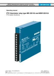
3 Connecting diagram<br />
4 Display and operation parts<br />
1 LEDs relay state<br />
2 Digital display, 5 digits<br />
3 LED speed measuring (1/min)<br />
4 LED frequency measuring (Hz)<br />
5 Pushbutton up<br />
6 Pushbutton set/reset<br />
7 Pushbutton down<br />
5 Programs<br />
2 programs (Pr) can be selected. Due to these Programs the <strong>de</strong>vice can be easily adapted to the<br />
application.<br />
Choose the Program fitting to your application and after that change the parameters! When changing the<br />
program all parameters are reseted upon "factory setting".<br />
(see chart " factory setting")<br />
Selecting the program:<br />
Keep the button "Set" pressed for 10 s when applying the supply voltage. Then program (Pr 1 ... Pr 2)<br />
can be choosen with the pushbuttons up/down and confirmed with set.<br />
Pr 1 = Revolutions control (factory setting) (1/min)<br />
Pr 2 = Frequency control (Hz)<br />
1) <strong>FR</strong><strong>MU</strong> only<br />
<strong>FR</strong>(<strong>MU</strong>)<strong>1000</strong> 12460-0701-03 Page 4 / 15 www.<strong>ziehl</strong>.<strong>de</strong>
6 Important Information<br />
DANGER!<br />
Hazardous voltage!<br />
Will cause <strong>de</strong>ath or serious injury. Turn off and lock out all power<br />
supplying this <strong>de</strong>vice before working on this <strong>de</strong>vice.<br />
To use the equipment flawless and safe, transport and store properly, install and start professionally and<br />
operate as directed.<br />
Only let persons work with the equipment who are familiar with installation, start and use and who have<br />
appropriate qualification corresponding to their function. They must observe the contents of the<br />
instructions manual, the information which are written on the equipment and the relevant security<br />
instructions for the setting up and the use of electrical units.<br />
The equipments are built according to DIN / EN and checked and leave the plant according to security in<br />
perfect condition. If, in any case the information in the instructions manual is not sufficient, please contact<br />
our company or the responsible representative.<br />
Instead of the industrial norms and regulations written in this instructions manual valid for Europe, you<br />
must observe out of their geographical scope the valid and relevant regulations of the corresponding<br />
country.<br />
Observe the maximum temperature permissible when installing in switching cabinet.<br />
Make sure sufficient space to other equipment or heat sources. If the cooling becomes<br />
more difficult e.g. through close proximity of apparatus with elevated surface<br />
temperature or hindrance of the cooling air, the tolerable environmental temperature is<br />
diminishing.<br />
!<br />
Attention!<br />
When all relays are programmed in operation current mo<strong>de</strong> (= pick up at alarm), a loss of the<br />
supply voltage or an instrument failure can remain uni<strong>de</strong>ntified. When the relay is applied as<br />
control instrument, the operator must ensure, that this error is recognized by regular<br />
examinations. We recommend to program and accordingly evaluate at least one relay in the<br />
closed-circuit current mo<strong>de</strong>.<br />
Universal power supply<br />
The <strong>de</strong>vice has got a universal power supply, that is suitable for DC- and AC-voltages. Before connecting<br />
the <strong>de</strong>vice to supply-voltage make sure that the connected voltage corresponds with the voltage on the<br />
lateral type on the <strong>de</strong>vice.<br />
<strong>FR</strong>(<strong>MU</strong>)<strong>1000</strong> 12460-0701-03 Page 5 / 15 www.<strong>ziehl</strong>.<strong>de</strong>
7 Installation<br />
The unit can be installed as follows:<br />
� Installation in switchgear cabinet on 35 mm mounting rail according to EN 60715<br />
� With screws M4 for installation on walls or panel. (additional latch inclu<strong>de</strong>d in <strong>de</strong>livery)<br />
Connection according to connection plan or type plate.<br />
8 Putting into operation<br />
Decimal point behind the last digit:<br />
Off = display mo<strong>de</strong>, displays values of measuring inputs<br />
On = menu mo<strong>de</strong>, select the menu items<br />
blinking = parameter setting mo<strong>de</strong><br />
8.1 Display mo<strong>de</strong><br />
Indication of the current measured value<br />
LEDs Relay (K1, K2)<br />
ON = relay picked up<br />
LED Speed (1/min) / Frequency (Hz)<br />
ON = according program selected<br />
Function button UP/DOWN<br />
Push short change into menu mo<strong>de</strong><br />
Push for > 2 s display of the stored MIN- or MAX-<br />
values of the choosen input<br />
Function button SET/RESET<br />
Push for 2 s Reset restart interlock<br />
Push for 4 s display of the choosen program<br />
Push for 10 s display of the software version<br />
8.2 Menu mo<strong>de</strong> (Decimal point behind the last digit ON)<br />
Selection of the menu items for changing the parameters.<br />
Function button UP/DOWN<br />
Push short Selection of menu item; Change into display mo<strong>de</strong><br />
Function button SET/RESET<br />
Push short Change into parameter setting mo<strong>de</strong><br />
8.3 Parameter setting mo<strong>de</strong> (Decimal point behind the last digit BLINKS)<br />
LEDs indicate relays concerned by the parameter setting.<br />
Function button UP/DOWN<br />
Press short/long Changement of parameter value (slow/fast)<br />
Function button SET/RESET<br />
Press short Acceptation of setting and choice of next parameters,<br />
after the last parameter change into menu mo<strong>de</strong><br />
Selecting the inputs (Inpvt):<br />
Choose menu item with up/down until InpVt and type alternate in display.<br />
Here it can be read, which input is selected.<br />
Enter in programming with Set.<br />
Select input with up/down and store with Set.<br />
Multiplier/divisor (Mvlt / div) :<br />
The indicated or limit value is calculated from the formula: input * Mvlt / div<br />
Mean value (SvM):<br />
Valid measured value = mean value from 1...8 (SvM) measuring cycles.<br />
<strong>FR</strong>(<strong>MU</strong>)<strong>1000</strong> 12460-0701-03 Page 6 / 15 www.<strong>ziehl</strong>.<strong>de</strong>
Setting the alarms (AL 1 / AL 2):<br />
Choose menu item with up/down until AL 1 and limit (limit value) alternate.<br />
Here it can be read clearly which limit value is programmed.<br />
Begin to program with set.<br />
Set limit with up/down and store with set. At window monitoring, this value is the lower limit of the<br />
window.<br />
Choose function:<br />
off Alarm OFF, relay is released all the time<br />
•:∆ Overspeed / overfrequency without reclosing lock<br />
•:: Overspeed / overfrequency with reclosing lock. Reset only possible after signal is below the limit<br />
(with hysterisis) and after the switchback-<strong>de</strong>lay. The switchback-<strong>de</strong>lay is indicated with blinking<br />
„A12L“ in the display.<br />
w_r Un<strong>de</strong>rspeed / un<strong>de</strong>rfrequency without reclosing lock<br />
w__ Un<strong>de</strong>rspeed / un<strong>de</strong>rfrequency with reclosing lock. Reset only possible after signal is below the<br />
limit (with hysterisis) and after the switchback-<strong>de</strong>lay. The switchback-<strong>de</strong>lay is indicated with blinking<br />
„A12L“ in the display..<br />
«k Window monitoring without reclosing lock.<br />
«« Window monitoring with reclosing lock. Reset only possible after signal is within the window (with<br />
hysterisis) and after the switchback-<strong>de</strong>lay. The switchback-<strong>de</strong>lay is indicated with „A12L“ in the<br />
display.<br />
ALHi upper limit at window monitoring. Lower limit = AL 1 set limit.<br />
Set Hysteresis<br />
Alarm <strong>de</strong>lay time dAL: An alarm is suppressed for this time, short-time exceeding of the limits does not<br />
cause an alarm.<br />
Switch-back <strong>de</strong>lay doF: Alarms are switched off this time after the signal has returned into good-state.<br />
Function of relay:<br />
r-Closed-current circuit mo<strong>de</strong>. Relay is picked up in GOOD and releases when the limit is excee<strong>de</strong>d =<br />
alarm. Advantage: errors and faults normally cause an alarm. Disadvantage: alarm also when<br />
supply-voltage is switched off and after switching on until the relay has picked up.<br />
A- <strong>Operating</strong>-current mo<strong>de</strong>: relay is released in GOOD state and picks up when the limit is excee<strong>de</strong>d.<br />
No alarm at errors and when supply-voltage is switched off.<br />
Start-up-<strong>de</strong>lay (dEnab):<br />
Monitoring starts this time after switching on the supply-voltage and after opening the enable -input E1-<br />
E2.<br />
Display <strong>de</strong>lay (ddisp):<br />
Defines the rate for updating the display. Set to higher values at nervous display.<br />
Simulation (Si):<br />
Here a measured input signal can be simulated with the buttons up/down. All functions of the <strong>de</strong>vice<br />
work as if this value was at the input. If no button is pressed for 15 minutes the <strong>de</strong>vice automatically<br />
switches back into the display mo<strong>de</strong>.<br />
Co<strong>de</strong>-lock (CodE):<br />
After setting all parameters they can be protected by activating the co<strong>de</strong> lock. After pushing Set, the<br />
display indicates Pin.<br />
Adjust with buttons up/down Pin 00504 (factory setting). After pushing Set, co<strong>de</strong> lock can be<br />
activated or switched off. After pushing Set again, an individual Pin can be selected (write down).<br />
When co<strong>de</strong> lock is activated all parameters can be seen but not be changed anymore.<br />
In case of problems with the co<strong>de</strong> lock (forgotten Pin) the lock can be switched off<br />
and the Pin can be set back to 00504, by pushing button set while connecting the<br />
<strong>de</strong>vice to supply-voltage until Cod / ofF is indicated in the display.<br />
<strong>FR</strong>(<strong>MU</strong>)<strong>1000</strong> 12460-0701-03 Page 7 / 15 www.<strong>ziehl</strong>.<strong>de</strong>
Tips:<br />
- With the pre-setting Pr1 and Pr2 the most important parameters can be set in advance, so that only little<br />
modifications are necessary , e.g. setting of the limits (limit values) for each alarm.<br />
- When the right <strong>de</strong>cimal point in the 7 segment display is on, the display mo<strong>de</strong> has been left, and the<br />
menu items can be chosen with up/down (menu mo<strong>de</strong>).<br />
- When the right <strong>de</strong>cimal point blinks, you are in the parameter setting mo<strong>de</strong> and can change the setting<br />
with up/down.<br />
- After finishing one menu item it is switched automatically on the next one.<br />
- Long pushing on up/down speeds up the changes in the display.<br />
- Pushing button up and down at the same time sets values to zero.<br />
- With reset (press Set/Reset for 2s) the display mo<strong>de</strong> can be reached from every position (exception:<br />
simulation) of the parameter setting mo<strong>de</strong> (the last selected value in is being stored).<br />
<strong>FR</strong>(<strong>MU</strong>)<strong>1000</strong> 12460-0701-03 Page 8 / 15 www.<strong>ziehl</strong>.<strong>de</strong>
8.4 Indications of the digital display<br />
Pr 1 / Pr 2 program number<br />
A1 , A2 alarm 1 , alarm 2 active<br />
A12 alarm 1 and alarm 2 active<br />
+ L alarm locked (locked), „reset“ is necessary.<br />
DEn<br />
remaining time until monitoring is activated<br />
(start-up-<strong>de</strong>lay dEnab is ending)<br />
Inpvt input<br />
U1-U2 frequency input (f - in)<br />
npn three wire proximity-switch NPN<br />
pnp three wire proxy-switch PNP or two wire proxy-switch<br />
mvlt multiplier<br />
div divisor<br />
Svm mean value<br />
AL 1, AL 2 alarm limit (lower limit when monitoring a window)<br />
Fvnc alarm function<br />
off alarm off<br />
•:∆ overspeed / over frequency without reclosing lock<br />
•:: overspeed / over frequency with reclosing lock.<br />
w_r un<strong>de</strong>rspeed / un<strong>de</strong>r frequency without reclosing lock<br />
w__ un<strong>de</strong>rspeed / un<strong>de</strong>r frequency with reclosing lock<br />
«k window monitoring without reclosing lock<br />
«« window monitoring with reclosing lock<br />
alhi upper limit when monitoring a window<br />
H hysterisis<br />
dal switching-<strong>de</strong>lay<br />
doF switch-back-<strong>de</strong>lay<br />
rEl function of relay<br />
r closed-current mo<strong>de</strong>, contacts 11-12 resp. 21-22 close at an alarm<br />
A operating-current mo<strong>de</strong>, contacts 11-14 (21-24) close at an alarm<br />
<strong>de</strong>nab start-up-<strong>de</strong>lay<br />
ddisp display <strong>de</strong>lay<br />
on, oFF on/off<br />
Si simulation<br />
CodE co<strong>de</strong> (pin)<br />
Pin ex works 00504<br />
<strong>FR</strong><strong>MU</strong> only:<br />
ovt analog output<br />
0-10 0...10 V voltage output<br />
0/4-20 0/4...20 mA current output<br />
____ value for 0 V, 0/4 mA at the output<br />
,,,, value for 10 V, 20 mA at the output<br />
<strong>FR</strong>(<strong>MU</strong>)<strong>1000</strong> 12460-0701-03 Page 9 / 15 www.<strong>ziehl</strong>.<strong>de</strong>
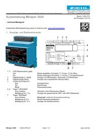
9 Operation<br />
9.1 Program 1: Pr1 / Speed Monitoring<br />
Menu mo<strong>de</strong><br />
<strong>FR</strong><strong>MU</strong><br />
only<br />
2 s = Max<br />
2 s = Min<br />
Inpvt<br />
mvlt<br />
div<br />
Svm<br />
AL 1<br />
AL 2<br />
<strong>de</strong>nab<br />
ddisp<br />
ovt<br />
CodE<br />
Display<br />
Si<br />
Typ<br />
Value<br />
Value<br />
Value<br />
Limit<br />
Limit<br />
Value<br />
Value<br />
Typ<br />
on /<br />
oFF<br />
....<br />
Pin<br />
U1-U2<br />
nPn<br />
pnp<br />
00001<br />
00250<br />
00001<br />
00250<br />
00001<br />
00008<br />
00005<br />
...99999<br />
0000.0<br />
...0060.0 s<br />
0000.1<br />
...0002.0 s<br />
oFF<br />
0-10<br />
0-20<br />
4-20<br />
00000<br />
...99999<br />
00000<br />
...09999<br />
Display mo<strong>de</strong><br />
Parameter setting mo<strong>de</strong><br />
fvnc off<br />
____ ,,,,<br />
3x Err<br />
00000<br />
...99999<br />
o.k.<br />
•:±<br />
•::<br />
w_r<br />
w__<br />
«k<br />
««<br />
on<br />
oFF<br />
00000<br />
...99999<br />
Zero Fullscale<br />
3x on / oFF<br />
<strong>FR</strong>(<strong>MU</strong>)<strong>1000</strong> 12460-0701-03 Page 10 / 15 www.<strong>ziehl</strong>.<strong>de</strong><br />
alHi<br />
Pin<br />
00005<br />
...99999<br />
dAL 000.05<br />
..099.99 s<br />
00000<br />
...09999<br />
H<br />
00001<br />
...<strong>1000</strong>0<br />
doF 000.05<br />
..099.99 s<br />
Operation with pushbuttons:<br />
Up<br />
Down<br />
rEL rA<br />
Set<br />
Reset<br />
= >2s Set<br />
Up/down at same time sets values<br />
on zero.<br />
Co<strong>de</strong>-reset = 2 s set while switching<br />
in.<br />
(Pin = 00504)<br />
error messages:<br />
Er 9 = <strong>de</strong>vice error<br />
Err = general error<br />
EEE = superordinated range
9.2 Program 2: Pr2 / Frequency Monitoring<br />
Menu mo<strong>de</strong><br />
<strong>FR</strong><strong>MU</strong><br />
only<br />
2 s = Max<br />
2 s = Min<br />
Inpvt<br />
Svm<br />
AL 1<br />
AL 2<br />
<strong>de</strong>nab<br />
ddisp<br />
ovt<br />
CodE<br />
Display<br />
Si<br />
Typ<br />
1...8<br />
Limit<br />
Limit<br />
Value<br />
Value<br />
Typ<br />
on /<br />
oFF<br />
....<br />
Pin<br />
U1-U2<br />
nPn<br />
pnp<br />
00001<br />
00008<br />
010.00<br />
...500.00<br />
0000.0<br />
...0060.0 s<br />
0000.1<br />
...0002.0 s<br />
oFF<br />
0-10<br />
0-20<br />
4-20<br />
010.00<br />
...500.00<br />
00000<br />
...09999<br />
Display mo<strong>de</strong><br />
Parameter setting mo<strong>de</strong><br />
fvnc off<br />
____ ,,,,<br />
3x Err<br />
000.00<br />
...500.00<br />
o.k.<br />
•:±<br />
•::<br />
w_r<br />
w__<br />
«k<br />
««<br />
<strong>FR</strong>(<strong>MU</strong>)<strong>1000</strong> 12460-0701-03 Page 11 / 15 www.<strong>ziehl</strong>.<strong>de</strong><br />
on<br />
oFF<br />
alHi<br />
Pin<br />
010.00<br />
...500.00<br />
dAL 000.05<br />
..099.99 s<br />
000.00<br />
...500.00<br />
Zero Fullscale<br />
00000<br />
...09999<br />
H<br />
3x on / oFF<br />
000.10<br />
...010.00<br />
doF 000.05<br />
..099.99 s<br />
Operation with pushbuttons:<br />
Up<br />
Down<br />
rEL rA<br />
Set<br />
Reset<br />
= >2s Set<br />
Up/down on same time sets values<br />
on zero.<br />
Co<strong>de</strong>-reset = 2 s set while switching<br />
in.<br />
(Pin = 00504)<br />
error messages:<br />
Er 9 = <strong>de</strong>vice error<br />
Err = general error<br />
EEE = superordinated range
10 Factory setting<br />
In case of programme change all parameters are set back on factory setting.<br />
Menuitem<br />
Parameter<br />
Value<br />
Pr 1 Pr 2<br />
Inpvt Input type PnP U1-U2<br />
mvlt Multiplier 1 -<br />
div Divisor 1 -<br />
svm Mean value 4 4<br />
Alarm 1<br />
AL 1<br />
Alarm 2<br />
AL 2<br />
Limit 1 (lower window limit) 500 48Z00<br />
Fvnc (Function) w_r «k<br />
alHi (upper window limit) - 52Z00<br />
H (Hysterisis) 10 1Z00<br />
dAL (Alarm-<strong>de</strong>lay) 0Z50 0Z10<br />
dof (Switch-back <strong>de</strong>lay) 0Z50 0Z10<br />
rel (Relais function) r r<br />
Limit 2 (lower window limit) 5000 47Z00<br />
Fvnc (Function) •:∆ «k<br />
alHi (upper window limit) - 53Z00<br />
H (Hysterisis) 100 1Z00<br />
dAL (Alarm-<strong>de</strong>lay) 0Z50 0Z10<br />
dof (Switch-back <strong>de</strong>lay) 0Z50 0Z10<br />
rel (Relais function) r r<br />
<strong>de</strong>nab Start-up-<strong>de</strong>lay 2Z0 0Z1<br />
ddisp Display <strong>de</strong>lay 0Z5 0Z5<br />
ovt Type 0-10 0-10<br />
(nur ____ (Zero) 0 0.00<br />
<strong>FR</strong><strong>MU</strong>) ,,,, (Fullscale) 5000 100Z00<br />
Co<strong>de</strong><br />
on / oFF<br />
Pin<br />
off<br />
00504<br />
off<br />
00504<br />
Indication of software version: push „Set“ 10 s in display mo<strong>de</strong>.<br />
11 Error search and measures<br />
My<br />
data<br />
Device cannot be programmed – Co<strong>de</strong> lock<br />
The co<strong>de</strong> lock gives protection against unauthorized manipulation of the <strong>de</strong>vice. When co<strong>de</strong> lock is<br />
activated the parameters can not be changed. The pin can be typed in by the user.<br />
Pin unknown? Make co<strong>de</strong>-reset: When switching in supply-voltage keep pushed button „Set“ for 2 s.<br />
Display shows: "88888"; "CodE"; "oFF"; "88888" release button „Set“.<br />
Co<strong>de</strong> = oFF, Pin = 00504.<br />
Indicated value does not correspond to input signal<br />
Correct program chosen?<br />
Input type (Inpvt) selected correct?<br />
Multiplier and divisor programmed correct when monitoring speed (PR 1)?<br />
Indication „Er9“<br />
Er9 is an internal fault of the <strong>de</strong>vice. Switch off- and on the power-supply.<br />
If after that there still is an error indicated, the unit must be sent to the factory for repair.<br />
<strong>FR</strong>(<strong>MU</strong>)<strong>1000</strong> 12460-0701-03 Page 12 / 15 www.<strong>ziehl</strong>.<strong>de</strong>
12 Technical data<br />
Rated supply voltage Us: AC/DC 24 – 240 V<br />
Tolerance DC 20,4 - 297 V AC 20 - 264 V<br />
Frequency 0, 40...500 Hz, from AC 80 V: 10...500 Hz<br />
Input < 3 W < 10 VA<br />
Relay-output: 2 x 1 Changer (CO)<br />
Switching voltage max. AC 400 V<br />
Switching current max. 5 A<br />
Switching power max. 1250 VA (ohm resistive load)<br />
max. 48 W at DC 24 V<br />
Nominal operating current Ie:<br />
AC15 Ie = 1,25 A Ue = 400 V<br />
Ie = 2 A Ue = 250 V<br />
DC13 Ie = 2 A Ue = 24 V<br />
Recommen<strong>de</strong>d fuse T 3,15 A (gL)<br />
Contact life mechanic 15 x 10 6 Switching cycles<br />
Contact life electrical. 2 x 10 5 Switching cycles at AC 250 V / 3 A<br />
5 x 10 5 Switching cycles at AC 250 V / 2 A<br />
1 x 10 5 Switching cycles at AC 250 V / 0,8 A<br />
Test conditions EN 60255 / EN 60947<br />
Rated impulse voltage 4000 V<br />
- measuring input f-in 4000 V -> Or<strong>de</strong>r-number U226134 + U226135<br />
6000 V -> Or<strong>de</strong>r-number U226138<br />
Contamination level 2<br />
Rated insulation voltage Ui 300 V<br />
- measuring input f-in 300 V -> Or<strong>de</strong>r-number U226134 + U226135<br />
600 V -> Or<strong>de</strong>r-number U226138<br />
On-time 100 %<br />
Permitted ambient air temperature -20 °C ... +60 °C<br />
EN 60068-2-2 dry heat<br />
Interference resistance EN 6<strong>1000</strong>-6-2<br />
Interference transmission EN 6<strong>1000</strong>-6-3<br />
Vibration resistance EN 60068-2-6 2…25 Hz ±1,6 mm<br />
25 ... 150 Hz 5 g<br />
<strong>FR</strong>(<strong>MU</strong>)<strong>1000</strong> 12460-0701-03 Page 13 / 15 www.<strong>ziehl</strong>.<strong>de</strong>
Measuring inputs<br />
f-in -> Or<strong>de</strong>r-number U226134 + U226135 Frequency 10,00 ... 500,00 Hz<br />
� admissible voltage AC 20...200 V<br />
� admissible voltage AC 80...440 V<br />
f-in -> Or<strong>de</strong>r-number U226138 Frequency 10,00 ... 500,00 Hz<br />
� admissible voltage AC 110...300 V<br />
� admissible voltage AC 210...830 V<br />
Three wire - PNP UMax 28 V; switching threshold approx. 10 V<br />
Three wire - NPN 18 V / 3,5 mA; switching threshold approx. 9 V<br />
Two wire- proximity switch 18 V / 3,5 mA ( 24 V DC )<br />
Switching threshold approx. 1,5 mA<br />
Switching frequency max. 1,6 kHz; 99999 1/min<br />
Cable length for proximity switch PNP, NPN, 2-wire<br />
Resistance of line ≤ 10 Ω / line<br />
Capacity of line ≤ 22 nF 0…800Hz; ≤ 10 nF 800...1600 Hz<br />
e.g. max. length of cable < 150 m with cable LIFYY11Y 3*0,34 mm<br />
at 0…800Hz<br />
Measuring error ± 0,05 % of measured value ± 1 Digit<br />
Temperature factor < 0,002 %/K<br />
Measuring time 1 Period * Svm (number mean values)<br />
>= 3 Periods; after placing the measuring signal<br />
Auxiliary supply +18 V 20 mA 16 ... 21 V max. 20 mA<br />
Enable E1-E2 18 V / 3 mA Switching threshold approx. 9 V<br />
Analogue output: (<strong>FR</strong><strong>MU</strong> only) electrically insulated to input f - in (U1-U2)<br />
Voltage output 0...10 V max. 10 mA error
61,8<br />
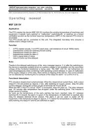
13 Type V4<br />
Dimensions in mm<br />
45<br />
58<br />
48<br />
16,5<br />
1 2 3<br />
1 Cover<br />
2 Base<br />
3 Bar for snap mounting<br />
4 Latch for sealing<br />
5 Front panel<br />
6 Position downward<br />
7 For fixing to wall with screws, Ø 4,2 mm.<br />
3<br />
(90)<br />
4<br />
Sie fin<strong>de</strong>n diese und weitere Betriebsanleitungen, soweit verfügbar auch in englisch, auf unserer Homepage<br />
www.<strong>ziehl</strong>.<strong>de</strong>.<br />
You find this and other operating-manuals on our homepage www.<strong>ziehl</strong>.<strong>de</strong>, as far as available also in<br />
English.<br />
<strong>FR</strong>(<strong>MU</strong>)<strong>1000</strong> 12460-0701-03 Page 15 / 15 www.<strong>ziehl</strong>.<strong>de</strong><br />
5<br />
116<br />
98<br />
6<br />
70<br />
Option<br />
7