Work Instruction for the Locator® Retentive System - Camlog
Work Instruction for the Locator® Retentive System - Camlog
Work Instruction for the Locator® Retentive System - Camlog

Create successful ePaper yourself
Turn your PDF publications into a flip-book with our unique Google optimized e-Paper software.
<strong>Work</strong> <strong>Instruction</strong><br />
<strong>for</strong> <strong>the</strong> Locator ®<br />
<strong>Retentive</strong> <strong>System</strong><br />
1. Introduction<br />
This work instruction serves as an addition<br />
to <strong>the</strong> instruction manual <strong>for</strong> <strong>the</strong> Locator ®<br />
abutment. It is intended to provide users<br />
who are not fully familiar with it with a clear<br />
instruction of <strong>the</strong> proper use of <strong>the</strong> system<br />
components.<br />
2. <strong>System</strong> Description<br />
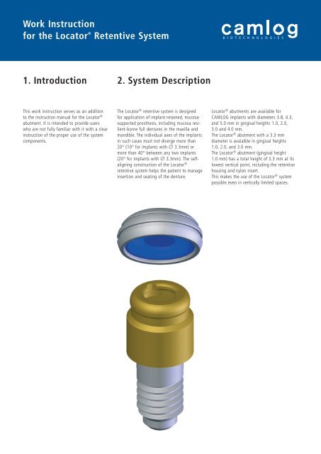
The Locator ® retentive system is designed<br />
<strong>for</strong> application of implant-retained, mucosasupported<br />
pros<strong>the</strong>sis, including mucosa resilient-borne<br />
full dentures in <strong>the</strong> maxilla and<br />
mandible. The individual axes of <strong>the</strong> implants<br />
in such cases must not diverge more than<br />
20° (10° <strong>for</strong> implants with Ø 3.3mm) or<br />
more than 40° between any two implants<br />
(20° <strong>for</strong> implants with Ø 3.3mm). The selfaligning<br />
construction of <strong>the</strong> Locator ®<br />
retentive system helps <strong>the</strong> patient to manage<br />
insertion and seating of <strong>the</strong> denture.<br />
Locator ® abutments are available <strong>for</strong><br />
CAMLOG implants with diameters 3.8, 4.3,<br />
and 5.0 mm in gingival heights 1.0, 2.0,<br />
3.0 and 4.0 mm.<br />
The Locator ® abutment with a 3.3 mm<br />
diameter is avaialble in gingival heights<br />
1.0, 2.0, and 3.0 mm.<br />
The Locator ® abutment (gingival height<br />
1.0 mm) has a total height of 3.3 mm at its<br />
lowest vertical point, including <strong>the</strong> retention<br />
housing and nylon insert.<br />
This makes <strong>the</strong> use of <strong>the</strong> Locator ® system<br />
possible even in vertically limited spaces.
<strong>Work</strong> <strong>Instruction</strong><br />
<strong>for</strong> <strong>the</strong> Locator ®<br />
<strong>Retentive</strong> <strong>System</strong><br />
2
5. Product Overview<br />
Art. No.<br />
J2253.3310<br />
J2253.3320<br />
J2253.3330<br />
J2253.3810<br />
J2253.3820<br />
J2253.3830<br />
J2253.3840<br />
J2253.4310<br />
J2253.4320<br />
J2253.4330<br />
J2253.4340<br />
J2253.5010<br />
J2253.5020<br />
J2253.5030<br />
J2253.5040<br />
J2253.0340<br />
J2253.0350<br />
J2253.0102<br />
J2253.0401<br />
Quantity<br />
1 p.<br />
1 p.<br />
1 p.<br />
1 p.<br />
4 p.<br />
4 p.<br />
2 p.<br />
20 p.<br />
p: piece<br />
per package<br />
Article<br />
Locator ® abutment<br />
- sterilizable -<br />
Ø 3.3 mm, GH 1.0 mm<br />
Ø 3.3 mm, GH 2.0 mm<br />
Ø 3.3 mm, GH 3.0 mm<br />
Locator ® abutment<br />
- sterilizable -<br />
Ø 3.8 mm, GH 1.0 mm<br />
Ø 3.8 mm, GH 2.0 mm<br />
Ø 3.8 mm, GH 3.0 mm<br />
Ø 3.8 mm, GH 4.0 mm<br />
Locator ® abutment<br />
- sterilizable -<br />
Ø 4.3 mm, GH 1.0 mm<br />
Ø 4.3 mm, GH 2.0 mm<br />
Ø 4.3 mm, GH 3.0 mm<br />
Ø 4.3 mm, GH 4.0 mm<br />
Locator ® abutment<br />
- sterilizable -<br />
Ø 5.0 mm, GH 1.0 mm<br />
Ø 5.0 mm, GH 2.0 mm<br />
Ø 5.0 mm, GH 3.0 mm<br />
Ø 5.0 mm, GH 4.0 mm<br />
Locator ® analog Ø 4.0 mm,<br />
<strong>for</strong> implants with Ø 3.3, Ø 3.8 mm<br />
Locator ® analog Ø 5.0 mm,<br />
<strong>for</strong> implants with Ø 4.3, Ø 5.0 mm<br />
Locator ® male processing<br />
package<br />
Consists of a replacement male<br />
(in clear, pink and blue), block-out<br />
spacer, and retention housing with<br />
black processing replacement male<br />
- disinfectable -<br />
Locator ® block-out spacer<br />
- disinfectable -<br />
GH = gingival height<br />
Material/Specifications<br />
Ti6Al4V with (TiN)<br />
titanium nitride coating<br />
Ti6Al4V with (TiN)<br />
titanium nitride coating<br />
Ti6Al4V with (TiN)<br />
titanium nitride coating<br />
Ti6Al4V with (TiN)<br />
titanium nitride coating<br />
Aluminium<br />
Aluminium<br />
retention housing (Ti6Al4V),<br />
processing replacement male<br />
(polyethylene),<br />
block-out spacer (teflon),<br />
replacement male (nylon)<br />
Teflon (white)<br />
3
<strong>Work</strong> <strong>Instruction</strong><br />
<strong>for</strong> <strong>the</strong> Locator ®<br />
<strong>Retentive</strong> <strong>System</strong><br />
4<br />
Art. No.<br />
J2253.0402<br />
J2253.1005<br />
J2253.1003<br />
J2253.1002<br />
J2253.2004<br />
J2253.2002<br />
J2253.0200<br />
J2253.0004<br />
J2253.0003<br />
J2253.0002<br />
J2253.0001<br />
Quantity<br />
4 p.<br />
4 p.<br />
4 p.<br />
4 p.<br />
4 p.<br />
4 p.<br />
4 p.<br />
4 p.<br />
1 p.<br />
1 p.<br />
1 p.<br />
Article<br />
Locator ® processing replacement<br />
male - disinfectable -<br />
Locator ® replacement male (clear)<br />
- disinfectable -<br />
Locator ® replacement male (pink)<br />
- disinfectable -<br />
Locator ® replacement male (blue)<br />
- disinfectable -<br />
Locator ® replacement male (green)<br />
<strong>for</strong> extended range<br />
Not <strong>for</strong> use with Ø 3.3 mm!<br />
- disinfectable -<br />
Locator ® replacement male (red)<br />
<strong>for</strong> extended range<br />
Not <strong>for</strong> use with Ø 3.3 mm!<br />
- disinfectable -<br />
Locator ® impression cap<br />
- disinfectable -<br />
Locator ® parallel post<br />
- disinfectable -<br />
Locator ® angle measurement guide<br />
- sterilizable -<br />
Locator ® core tool<br />
3-piece<br />
- sterilizable -<br />
Driver <strong>for</strong> Locator ® abutment<br />
manual/ratchet<br />
- sterilizable -<br />
Material/Specifications<br />
polyethylene (black)<br />
nylon<br />
retention <strong>for</strong>ce: 22.3 N/2‘270 g<br />
axis divergence: 0°-10°<br />
nylon<br />
retention <strong>for</strong>ce: 13.4 N/1‘365 g<br />
axis divergence: 0°-10°<br />
nylon<br />
retention <strong>for</strong>ce: 6.7 N/680 g<br />
axis divergence: 0°-10°<br />
nylon<br />
retention <strong>for</strong>ce: 17.8 N/1’815 g<br />
axis divergence: 10°-20°<br />
nylon<br />
retention <strong>for</strong>ce: 6.7 N/680 g<br />
axis divergence: 10°-20°<br />
aluminium housing with black<br />
processing replacement male<br />
(polyethylene)<br />
polyethylene<br />
stainless steel<br />
stainless steel<br />
replacement male removal tip,<br />
replacement male seating tool,<br />
gold-colored driver <strong>for</strong> Locator ®<br />
abutment<br />
stainless steel
6. Application of <strong>the</strong> Locator ® core tool<br />
The Locator ® core tool consists of three<br />
screw connected parts.<br />
To remove a processing replacement male<br />
or replacement male disengage <strong>the</strong> screw<br />
connected tip three turns anti-clockwise and<br />
plug it into <strong>the</strong> removing male. When<br />
removing, <strong>the</strong> male is held by <strong>the</strong> sharp<br />
retention edge. To remove <strong>the</strong> male from<br />
<strong>the</strong> tip turn it fully clockwise onto <strong>the</strong> tool.<br />
<strong>Retentive</strong> tip<br />
to remove males<br />
Center part<br />
to replace males<br />
To insert a processing replacement male<br />
or replacement male into <strong>the</strong> retention<br />
housing use <strong>the</strong> center part of <strong>the</strong> tool.<br />
Screw off <strong>the</strong> retentive tip. Attach one of<br />
<strong>the</strong> males on <strong>the</strong> visible end and push it<br />
completely into <strong>the</strong> housing.<br />
The gold colored end piece can be unscrewed<br />
and be used as a driver <strong>for</strong> <strong>the</strong><br />
Locator ® abutment.<br />
Gold colored end piece<br />
(driver)<br />
5
<strong>Work</strong> <strong>Instruction</strong><br />
<strong>for</strong> <strong>the</strong> Locator ®<br />
<strong>Retentive</strong> <strong>System</strong><br />
7. Application<br />
6<br />
The divergence of <strong>the</strong> implant axes<br />
between two implants must not exceed<br />
40° (20° per implant). With implants of<br />
3.3 mm diameter, <strong>the</strong> divergence must<br />
not exceed 20° (10° per implant).<br />
Be<strong>for</strong>e selecting <strong>the</strong> appropriate Locator ®<br />
abutment <strong>the</strong> implant diameter and gingival<br />
height must be known.<br />
Select <strong>the</strong> height of <strong>the</strong> Locator ® abutment<br />
in relation to <strong>the</strong> gingival height. The exact<br />
height of <strong>the</strong> abutment has been selected<br />
when <strong>the</strong> functional area extends 1.5 mm<br />
above <strong>the</strong> surrounding tissue.<br />
The functional area must never be<br />
positioned below <strong>the</strong> gingiva level!<br />
7.1 Locator ® abutment insertion<br />
Remove <strong>the</strong> healing cap and clean <strong>the</strong> inside<br />
of <strong>the</strong> implant. Make sure that <strong>the</strong> contact<br />
surface between implant and abutment is<br />
free of bone and soft tissue. This is <strong>the</strong> only<br />
way to ensure satisfactory seating of <strong>the</strong><br />
abutment on <strong>the</strong> implant.<br />
When inserting <strong>the</strong> Locator ® abutment into<br />
<strong>the</strong> implant, use <strong>the</strong> driver <strong>for</strong> Locator ®<br />
abutment manual or <strong>the</strong> gold-colored driver<br />
of <strong>the</strong> Locator ® core tool.<br />
Locator ® abutments must be secured<br />
during insertion into <strong>the</strong> mouth to<br />
prevent aspiration (e.g. with dental floss).<br />
Locator ® abutments with 3.3 mm diameter<br />
are tightened with a torque of<br />
20 Ncm. Abutments with 3.8, 4.3, and<br />
5.0 mm diameters are tightened with a<br />
torque of 30 Ncm. The abutments must<br />
be retightened after 5 minutes with <strong>the</strong><br />
respective torque.<br />
7.2 Measurement of implant axis with<br />
parallel posts and <strong>the</strong> angle measurement<br />
guide<br />
The black parallel posts are slipped onto <strong>the</strong><br />
inserted abutments until detectable pressure<br />
is felt. Then use <strong>the</strong> Locator ® angle measurement<br />
guide to measure <strong>the</strong> angles of <strong>the</strong><br />
individual implant abutments.<br />
Up to an angle of 10° per implant (up to<br />
20° between two implants) three replacement<br />
males can be selected: clear: 22.3 N/<br />
2270 g, pink: 13.4 N/1365 g, and blue:<br />
6.7 N/680 g.<br />
The following replacement males <strong>for</strong> axial<br />
divergences of 10° - 20° per implant are<br />
available (extended range):<br />
green: 17.8 N/1815 g, and red: 6.7 N/680 g.<br />
With Ø 3.3 mm implants, <strong>the</strong>se males must<br />
not be used!
7.3 Incorporation of <strong>the</strong> retention<br />
housing<br />
The placement of <strong>the</strong> retention housing (supplied<br />
in each laboratory set) can be done ei<strong>the</strong>r<br />
in <strong>the</strong> dental laboratory or chairside.<br />
Tip: A metal cast streng<strong>the</strong>ns <strong>the</strong> stability<br />
of <strong>the</strong> denture.<br />
7.3.1 Fabrication of a new denture with<br />
Locator ® components<br />
The Locator ® components are directly<br />
incorporated into <strong>the</strong> new denture during<br />
processing.<br />
Insert <strong>the</strong> Locator ® abutments of matched<br />
diameters and gingival heights in <strong>the</strong> manner<br />
described in 7.1 "Locator ® abutment insertion"<br />
on page 6.<br />
Locator ® abutments must be secured<br />
during insertion into <strong>the</strong> mouth to prevent<br />
aspiration (e.g. with dental floss).<br />
Locator ® abutments with 3.3 mm diameter<br />
are tightened with a torque of<br />
20 Ncm, and abutments with 3.8, 4.3,<br />
and 5.0 mm diameters are tightened with<br />
a torque of 30 Ncm. The abutments must<br />
be retightened after 5 minutes with <strong>the</strong><br />
respective torque.<br />
Chairside:<br />
Place a Locator ® impression cap on each<br />
Locator ® abutment <strong>for</strong> <strong>the</strong> functional<br />
impression. Make sure that <strong>the</strong> impression<br />
cap is properly seated during <strong>the</strong> procedure.<br />
Use a firm impression material (e.g. polye<strong>the</strong>r<br />
or silicone) to ensure that <strong>the</strong> impression cap<br />
will remain securely in <strong>the</strong> impression.<br />
In <strong>the</strong> dental lab:<br />
After <strong>the</strong> impression is taken, place <strong>the</strong><br />
analogs (Ø 4.0 mm or Ø 5.0 mm) into <strong>the</strong><br />
impression caps and fabricate <strong>the</strong> master<br />
cast.<br />
After <strong>the</strong> master cast is finished, place <strong>the</strong><br />
white block-out spacer (supplied with <strong>the</strong><br />
male processing package) over <strong>the</strong> functional<br />
areas of <strong>the</strong> Locator ® analogs to prevent<br />
acrylic from penetrating into <strong>the</strong> retention<br />
housing.<br />
Mount <strong>the</strong> retention housings with <strong>the</strong> black<br />
processing replacement male on each analog<br />
over <strong>the</strong> previously inserted block-out spacer<br />
until pressure is felt. The black processing<br />
replacement male will ensure both secure<br />
seating <strong>for</strong> <strong>the</strong> retention housing and<br />
resilience.<br />
Selection of matching analogs<br />
Locator ® impression cap<br />
Undercuts between <strong>the</strong> retention housing<br />
and surrounding tissue which <strong>the</strong> blockout<br />
spacer does not reach must be blocked<br />
out. Do not allow any acrylic to enter<br />
<strong>the</strong> retention housing during processing!<br />
The denture can be completed by <strong>the</strong> conventional<br />
technique.<br />
Locator ® analog Ø 4.0 mm Locator ® analog Ø 5.0 mm<br />
Locator ®<br />
abutment<br />
Ø 3.3 mm<br />
Locator ®<br />
abutment<br />
Ø 3.8 mm<br />
Locator ®<br />
abutment<br />
Ø 4.3 mm<br />
Locator ®<br />
abutment<br />
Ø 5.0 mm<br />
7
<strong>Work</strong> <strong>Instruction</strong><br />
<strong>for</strong> <strong>the</strong> Locator ®<br />
<strong>Retentive</strong> <strong>System</strong><br />
Insertion of <strong>the</strong> replacement males<br />
After completion of <strong>the</strong> denture, remove <strong>the</strong><br />
white block-out spacer.<br />
Be<strong>for</strong>e insertion into <strong>the</strong> mouth, replace <strong>the</strong><br />
black processing replacement males with<br />
respective colored replacement males with<br />
<strong>the</strong> aid of <strong>the</strong> Locator ® core tool.<br />
Insert <strong>the</strong> grip on <strong>the</strong> tip into <strong>the</strong> black<br />
processing replacement male and pull it out<br />
from <strong>the</strong> retention housing.<br />
With <strong>the</strong> seating tool of <strong>the</strong> Locator ® core<br />
tool (middle piece) insert <strong>the</strong> appropriate<br />
replacement male into <strong>the</strong> empty retention<br />
housing, to match <strong>the</strong> angle and <strong>the</strong> desired<br />
retentive <strong>for</strong>ce.<br />
8<br />
The replacement males have no friction<br />
on <strong>the</strong> seating tool. There<strong>for</strong>e keep <strong>the</strong><br />
seating tool perpendicular and insert <strong>the</strong><br />
replacement male from basal direction.<br />
7.3.2 Adjusting an existing denture<br />
with Locator ® components<br />
Locator ® components can be incorporated<br />
into an existing full denture.<br />
Insert <strong>the</strong> Locator ® abutments of matched<br />
diameters and gingival heights in <strong>the</strong> manner<br />
described in 7.1 "Locator ® abutment insertion"<br />
on page 6.<br />
Locator ® abutments must be secured<br />
during insertion in <strong>the</strong> mouth to prevent<br />
aspiration (e.g. with dental floss).<br />
Locator ® abutments with 3.3 mm diameter<br />
are tightened with a torque of<br />
20 Ncm. Abutments with 3.8, 4.3, and<br />
5.0 mm diameters are tightened with a<br />
torque of 30 Ncm. The abutments must<br />
be retightened after 5 minutes with <strong>the</strong><br />
respective torque.<br />
Chairside:<br />
Place a Locator ® impression cap on each<br />
Locator ® abutment <strong>for</strong> <strong>the</strong> functional<br />
impression. Make sure that <strong>the</strong> impression<br />
cap is properly seated during <strong>the</strong> procedure.<br />
Relieve <strong>the</strong> existing denture in <strong>the</strong> areas of<br />
<strong>the</strong> impression caps.<br />
The impression caps mounted on <strong>the</strong><br />
Locator ® abutments should not touch <strong>the</strong><br />
denture during <strong>the</strong> oral try-in.<br />
In <strong>the</strong> case of a small denture base, it is also<br />
possible to take an impression with retention<br />
housings with <strong>the</strong> black processing replacement<br />
males. Be aware of <strong>the</strong> reduced retention<br />
potential in <strong>the</strong> impression material.<br />
Take <strong>the</strong> impression with <strong>the</strong> relieved denture<br />
directly over <strong>the</strong> impression caps. Use only an
appropriate impression material (e.g.<br />
polye<strong>the</strong>r or silicone) to ensure that <strong>the</strong><br />
impression caps will remain securely in <strong>the</strong><br />
impression.<br />
In <strong>the</strong> dental lab:<br />
The matching analog is selected as described<br />
in <strong>the</strong> diagram "In <strong>the</strong> dental lab: Selection<br />
of matching analogs" on page 7, and<br />
inserted into <strong>the</strong> impression caps in <strong>the</strong><br />
impression. Fabricate <strong>the</strong> master cast and<br />
ensure <strong>the</strong> fixation of <strong>the</strong> defined position<br />
and occlusal height of <strong>the</strong> denture and<br />
occlusal plane.<br />
After <strong>the</strong> master cast is finished, place <strong>the</strong><br />
white block-out spacer (supplied with <strong>the</strong><br />
male processing package) over <strong>the</strong> functional<br />
areas of <strong>the</strong> Locator ® analogs to prevent<br />
acrylic from penetrating into <strong>the</strong> retention<br />
housing.<br />
Mount <strong>the</strong> retention housing with <strong>the</strong> black<br />
processing replacement male over <strong>the</strong><br />
previously inserted block-out spacer until<br />
pressure is felt. The black processing replacement<br />
male will ensure both secure seating<br />
<strong>for</strong> <strong>the</strong> retention housing and resilience.<br />
Undercuts between <strong>the</strong> retention housing<br />
and surrounding tissue which <strong>the</strong> blockout<br />
spacer does not reach must be blocked<br />
out. Do not allow any acrylic to enter<br />
<strong>the</strong> retention housing during preparation!<br />
Do cure <strong>the</strong> retention housings into <strong>the</strong> relieved<br />
denture base.<br />
After <strong>the</strong> denture has been finished and<br />
polished, remove <strong>the</strong> black processing replacement<br />
males as described in "Insertion of<br />
<strong>the</strong> replacement males" on page 8, and<br />
exchange <strong>the</strong>m with <strong>the</strong> matching replacement<br />
males.<br />
Insert <strong>the</strong> finished denture and check <strong>the</strong><br />
occlusion.<br />
7.3.3 Adjusting an existing denture<br />
with Locator ® components in <strong>the</strong><br />
dentist’s office<br />
Locator ® components can also be incorporated<br />
into an existing full denture in <strong>the</strong> dentist's<br />
office. Locator ® abutments of matched<br />
diameters and gingival heights are inserted in<br />
<strong>the</strong> manner described in 7.1 "Locator ® abutment<br />
insertion" on page 6.<br />
Locator ® abutments must be secured<br />
during insertion in <strong>the</strong> mouth to prevent<br />
aspiration (e.g. with dental floss).<br />
Locator ® abutments with 3.3 mm diameter<br />
are tightened with a torque of<br />
20 Ncm. Abutments with 3.8, 4.3, and<br />
5.0 mm diameters are tightened with a<br />
torque of 30 Ncm. The abutments must<br />
be retightened after 5 minutes with <strong>the</strong><br />
respective torque.<br />
Place <strong>the</strong> white block-out spacer (supplied<br />
with <strong>the</strong> male processing package) over <strong>the</strong><br />
functional areas of <strong>the</strong> Locator ® abutments<br />
to prevent acrylic from penetrating into <strong>the</strong><br />
retention housings.<br />
Mount <strong>the</strong> retention housings with <strong>the</strong> black<br />
processing replacement males over <strong>the</strong><br />
previously inserted block-out spacer until<br />
pressure is felt.<br />
The black processing replacement male will<br />
ensure both secure seating <strong>for</strong> <strong>the</strong> retention<br />
housing and resilience.<br />
Undercuts between <strong>the</strong> retention housing<br />
and surrounding tissue which <strong>the</strong> blockout<br />
spacer does not reach must be blocked<br />
out. Do not allow any acrylic to enter<br />
<strong>the</strong> retention housing during preparation!<br />
9
<strong>Work</strong> <strong>Instruction</strong><br />
<strong>for</strong> <strong>the</strong> Locator ®<br />
<strong>Retentive</strong> <strong>System</strong><br />
Carefully relieve <strong>the</strong> denture at <strong>the</strong> intended<br />
area <strong>for</strong> <strong>the</strong> retention housings and <strong>the</strong>n<br />
per<strong>for</strong>ate it above <strong>the</strong> housings (as a release<br />
<strong>for</strong> excess acrylic and <strong>for</strong> checking). Grind <strong>the</strong><br />
denture area intended <strong>for</strong> <strong>the</strong> retention<br />
housings sufficiently to permit <strong>the</strong> inserted<br />
denture to be seated over <strong>the</strong> housings<br />
without making contact. Any contact can<br />
alter <strong>the</strong> proper fit of <strong>the</strong> denture.<br />
To cure <strong>the</strong> retention housings, apply selfcuring<br />
acrylic and process it in accordance<br />
with manufacturer instructions. Apply a<br />
small amount into <strong>the</strong> relieved areas in <strong>the</strong><br />
denture and also apply some to <strong>the</strong> retention<br />
housings as well.<br />
Remove <strong>the</strong> denture from <strong>the</strong> patient's mouth<br />
after <strong>the</strong> acrylic has cured, remove excess<br />
acrylic, and polish.<br />
Remove <strong>the</strong> black processing replacement<br />
males as described in "Insertion of <strong>the</strong><br />
replacement males" on page 8, and exchange<br />
<strong>the</strong>m with <strong>the</strong> according replacement males.<br />
Insert <strong>the</strong> finished denture and check <strong>the</strong><br />
occlusion.<br />
10<br />
7.4 Exchange of <strong>the</strong> replacement males<br />
Follow <strong>the</strong> same procedure in exchanging<br />
<strong>the</strong> replacement males as <strong>for</strong> removal of <strong>the</strong><br />
processing replacement males with <strong>the</strong><br />
Locator ® core tool and insertion with <strong>the</strong><br />
seating tool (middle piece).<br />
7.5 Restoring or relining of <strong>the</strong> denture<br />
base<br />
Chairside:<br />
Remove all colored replacement males from<br />
<strong>the</strong> retention housings in <strong>the</strong> denture as<br />
described in "7.4 Exchange of <strong>the</strong> replacement<br />
males" and replace <strong>the</strong>m with <strong>the</strong> black<br />
processing replacement males.<br />
The black processing replacement male will<br />
ensure secure fixation of <strong>the</strong> denture while<br />
taking <strong>the</strong> impression. Do not apply any<br />
impression material in or around <strong>the</strong><br />
Locator ® .<br />
While taking a relining impression, make sure<br />
<strong>the</strong> denture is correctly seated on <strong>the</strong><br />
Locator ® abutments.<br />
Leave <strong>the</strong> black processing replacement<br />
males in <strong>the</strong> retention housings after removal<br />
of <strong>the</strong> relined denture base.
In <strong>the</strong> dental lab:<br />
Selection of analogs as described in <strong>the</strong><br />
diagram "In <strong>the</strong> dental lab: Selection of<br />
matching analogs" on page 7.<br />
After <strong>the</strong> impression is taken, place <strong>the</strong><br />
analogs (Ø 4.0 mm or Ø 5.0 mm) into <strong>the</strong><br />
retention housings and fabricate <strong>the</strong> relining<br />
model.<br />
It is advisable to use a new male processing<br />
package. Alternatively, carefully<br />
remove <strong>the</strong> previous retention housing<br />
from <strong>the</strong> denture and re-use it.<br />
Be<strong>for</strong>e relining <strong>the</strong> denture, place <strong>the</strong> white<br />
block-out spacer over <strong>the</strong> functional areas of<br />
<strong>the</strong> Locator ® analogs to prevent <strong>the</strong> acrylic<br />
from penetrating into <strong>the</strong> retention housings.<br />
Mount <strong>the</strong> retention housings with <strong>the</strong> black<br />
processing replacement males over each<br />
analog over <strong>the</strong> previously inserted block-out<br />
spacer until pressure is felt. The black<br />
processing replacement males will ensure<br />
both secure seating <strong>for</strong> <strong>the</strong> retention<br />
housings and resilience.<br />
Undercuts between <strong>the</strong> retention housing<br />
and surrounding tissue which <strong>the</strong> blockout<br />
spacer does not reach must be<br />
blocked out. Do not allow any acrylic to<br />
enter <strong>the</strong> retention housings during<br />
preparation!<br />
The denture can be relined by <strong>the</strong> conventional<br />
technique.<br />
After <strong>the</strong> denture has been finished and<br />
polished, remove <strong>the</strong> black processing replacement<br />
males as described in ”Insertion of<br />
<strong>the</strong> replacement males” on page 8, and<br />
exchange <strong>the</strong>m with <strong>the</strong> respective replacement<br />
males.<br />
Insert <strong>the</strong> finished denture and check <strong>the</strong><br />
occlusion.<br />
8. Explanation<br />
of Symbols<br />
Components are delivered<br />
NON-STERILE.<br />
WARNING! Comply with <strong>the</strong><br />
<strong>Instruction</strong> Manual<br />
Not <strong>for</strong> re-use<br />
Lot designation<br />
Article Number<br />
Color-coding of <strong>the</strong> diameters in <strong>the</strong><br />
CAMLOG ® Implant <strong>System</strong>:<br />
Color<br />
Grey<br />
Yellow<br />
Red<br />
Blue<br />
Green<br />
Implant diameter<br />
3.3 mm<br />
3.8 mm<br />
4.3 mm<br />
5.0 mm<br />
6.0 mm<br />
11
Headquarters:<br />
CAMLOG Biotechnologies AG<br />
Margare<strong>the</strong>nstrasse 38<br />
CH-4053 Basel<br />
Phone +41 (0) 61/565 41 00<br />
Fax +41 (0) 61/565 41 01<br />
info@camlog.com<br />
www.camlog.com<br />
Manufacturer Locator ® :<br />
Zest Anchors, Inc.<br />
Escondido, CA 92029<br />
USA<br />
Locator ® is a registered trademark of<br />
Zest Anchors, Inc.<br />
Visit our website at www.camlog.com.<br />
Subject to change · X.J8000.0039 Rev.0