Work Instruction for the Locator® Retentive System - Camlog
Work Instruction for the Locator® Retentive System - Camlog
Work Instruction for the Locator® Retentive System - Camlog

You also want an ePaper? Increase the reach of your titles
YUMPU automatically turns print PDFs into web optimized ePapers that Google loves.
<strong>Work</strong> <strong>Instruction</strong><br />
<strong>for</strong> <strong>the</strong> Locator ®<br />
<strong>Retentive</strong> <strong>System</strong><br />
7. Application<br />
6<br />
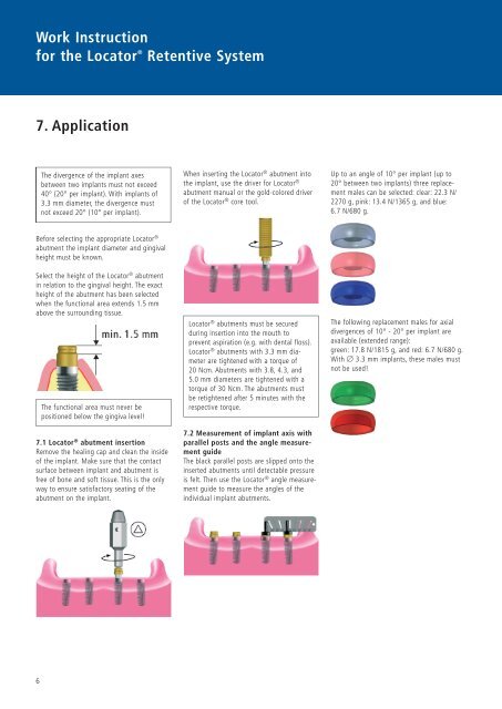
The divergence of <strong>the</strong> implant axes<br />
between two implants must not exceed<br />
40° (20° per implant). With implants of<br />
3.3 mm diameter, <strong>the</strong> divergence must<br />
not exceed 20° (10° per implant).<br />
Be<strong>for</strong>e selecting <strong>the</strong> appropriate Locator ®<br />
abutment <strong>the</strong> implant diameter and gingival<br />
height must be known.<br />
Select <strong>the</strong> height of <strong>the</strong> Locator ® abutment<br />
in relation to <strong>the</strong> gingival height. The exact<br />
height of <strong>the</strong> abutment has been selected<br />
when <strong>the</strong> functional area extends 1.5 mm<br />
above <strong>the</strong> surrounding tissue.<br />
The functional area must never be<br />
positioned below <strong>the</strong> gingiva level!<br />
7.1 Locator ® abutment insertion<br />
Remove <strong>the</strong> healing cap and clean <strong>the</strong> inside<br />
of <strong>the</strong> implant. Make sure that <strong>the</strong> contact<br />
surface between implant and abutment is<br />
free of bone and soft tissue. This is <strong>the</strong> only<br />
way to ensure satisfactory seating of <strong>the</strong><br />
abutment on <strong>the</strong> implant.<br />
When inserting <strong>the</strong> Locator ® abutment into<br />
<strong>the</strong> implant, use <strong>the</strong> driver <strong>for</strong> Locator ®<br />
abutment manual or <strong>the</strong> gold-colored driver<br />
of <strong>the</strong> Locator ® core tool.<br />
Locator ® abutments must be secured<br />
during insertion into <strong>the</strong> mouth to<br />
prevent aspiration (e.g. with dental floss).<br />
Locator ® abutments with 3.3 mm diameter<br />
are tightened with a torque of<br />
20 Ncm. Abutments with 3.8, 4.3, and<br />
5.0 mm diameters are tightened with a<br />
torque of 30 Ncm. The abutments must<br />
be retightened after 5 minutes with <strong>the</strong><br />
respective torque.<br />
7.2 Measurement of implant axis with<br />
parallel posts and <strong>the</strong> angle measurement<br />
guide<br />
The black parallel posts are slipped onto <strong>the</strong><br />
inserted abutments until detectable pressure<br />
is felt. Then use <strong>the</strong> Locator ® angle measurement<br />
guide to measure <strong>the</strong> angles of <strong>the</strong><br />
individual implant abutments.<br />
Up to an angle of 10° per implant (up to<br />
20° between two implants) three replacement<br />
males can be selected: clear: 22.3 N/<br />
2270 g, pink: 13.4 N/1365 g, and blue:<br />
6.7 N/680 g.<br />
The following replacement males <strong>for</strong> axial<br />
divergences of 10° - 20° per implant are<br />
available (extended range):<br />
green: 17.8 N/1815 g, and red: 6.7 N/680 g.<br />
With Ø 3.3 mm implants, <strong>the</strong>se males must<br />
not be used!