Work Instruction for the Locator® Retentive System - Camlog
Work Instruction for the Locator® Retentive System - Camlog
Work Instruction for the Locator® Retentive System - Camlog

Create successful ePaper yourself
Turn your PDF publications into a flip-book with our unique Google optimized e-Paper software.
In <strong>the</strong> dental lab:<br />
Selection of analogs as described in <strong>the</strong><br />
diagram "In <strong>the</strong> dental lab: Selection of<br />
matching analogs" on page 7.<br />
After <strong>the</strong> impression is taken, place <strong>the</strong><br />
analogs (Ø 4.0 mm or Ø 5.0 mm) into <strong>the</strong><br />
retention housings and fabricate <strong>the</strong> relining<br />
model.<br />
It is advisable to use a new male processing<br />
package. Alternatively, carefully<br />
remove <strong>the</strong> previous retention housing<br />
from <strong>the</strong> denture and re-use it.<br />
Be<strong>for</strong>e relining <strong>the</strong> denture, place <strong>the</strong> white<br />
block-out spacer over <strong>the</strong> functional areas of<br />
<strong>the</strong> Locator ® analogs to prevent <strong>the</strong> acrylic<br />
from penetrating into <strong>the</strong> retention housings.<br />
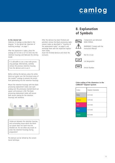
Mount <strong>the</strong> retention housings with <strong>the</strong> black<br />
processing replacement males over each<br />
analog over <strong>the</strong> previously inserted block-out<br />
spacer until pressure is felt. The black<br />
processing replacement males will ensure<br />
both secure seating <strong>for</strong> <strong>the</strong> retention<br />
housings and resilience.<br />
Undercuts between <strong>the</strong> retention housing<br />
and surrounding tissue which <strong>the</strong> blockout<br />
spacer does not reach must be<br />
blocked out. Do not allow any acrylic to<br />
enter <strong>the</strong> retention housings during<br />
preparation!<br />
The denture can be relined by <strong>the</strong> conventional<br />
technique.<br />
After <strong>the</strong> denture has been finished and<br />
polished, remove <strong>the</strong> black processing replacement<br />
males as described in ”Insertion of<br />
<strong>the</strong> replacement males” on page 8, and<br />
exchange <strong>the</strong>m with <strong>the</strong> respective replacement<br />
males.<br />
Insert <strong>the</strong> finished denture and check <strong>the</strong><br />
occlusion.<br />
8. Explanation<br />
of Symbols<br />
Components are delivered<br />
NON-STERILE.<br />
WARNING! Comply with <strong>the</strong><br />
<strong>Instruction</strong> Manual<br />
Not <strong>for</strong> re-use<br />
Lot designation<br />
Article Number<br />
Color-coding of <strong>the</strong> diameters in <strong>the</strong><br />
CAMLOG ® Implant <strong>System</strong>:<br />
Color<br />
Grey<br />
Yellow<br />
Red<br />
Blue<br />
Green<br />
Implant diameter<br />
3.3 mm<br />
3.8 mm<br />
4.3 mm<br />
5.0 mm<br />
6.0 mm<br />
11