CONELOG® Implant System Prosthetic Restorations - Camlog
CONELOG® Implant System Prosthetic Restorations - Camlog
CONELOG® Implant System Prosthetic Restorations - Camlog

You also want an ePaper? Increase the reach of your titles
YUMPU automatically turns print PDFs into web optimized ePapers that Google loves.
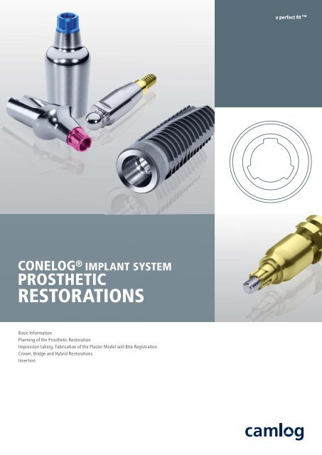
CONELOG ® IMPLANT SYSTEM<br />
PROSTHETIC<br />
RESTORATIONS<br />
Basic Information<br />
Planning of the <strong>Prosthetic</strong> Restoration<br />
Impression taking, Fabrication of the Plaster Model and Bite Registration<br />
Crown, Bridge and Hybrid <strong>Restorations</strong><br />
Insertion<br />
a perfect fit ©<br />
a perfect fit
CONELOG ® IMPLANT SYSTEM<br />
PROSTHETIC RESTORATIONS<br />
2
TABLE OF CONTENTS<br />
GENERAL SYSTEM INFORMATION ABOUT THE CAMLOG ® AND CONELOG ®<br />
IMPLANT SYSTEM<br />
CONELOG ® IMPLANT SYSTEM<br />
PROSTHETIC RESTORATIONS<br />
SYSTEM INTRODUCTION<br />
GENERAL GUIDELINES FOR THE FABRICATION OF IMPLANT-SUPPORTED PROSTHETICS 5<br />
CONELOG ® IMPLANT ABUTMENT CONNECTION 6<br />
CONELOG ® IMPLANT/BAR ABUTMENT/BALL ABUTMENT CONNECTION 7<br />
CONELOG ® 5<br />
5<br />
6<br />
7<br />
PROSTHETIC COMPONENTS<br />
8<br />
PLANNING OF THE PROSTHETIC RESTORATION<br />
CONELOG ® IMPRESSION TAKING<br />
CONELOG ® CAST FABRICATION<br />
CONELOG ® BITE REGISTRATION POSTS<br />
CONELOG ® TEMPORARY RESTORATION<br />
CONELOG ® ESTHOMIC ® LINE OF ABUTMENTS<br />
CONELOG ® LOGFIT ® PROSTHETIC SYSTEM<br />
CONELOG ® GOLD-PLASTIC ABUTMENT<br />
CONELOG ® UNIVERSAL AND TELESCOPE ABUTMENT<br />
CONELOG ® TITANIUM BASE CAD/CAM<br />
CONELOG ® VARIO SR ABUTMENTS<br />
CONELOG ® BAR ABUTMENT<br />
CONELOG ® BALL ABUTMENT<br />
CONELOG ® LOCATOR ® ABUTMENT<br />
ACCESSORIES AND PROSTHETIC INSTRUMENTS<br />
MATERIALS<br />
FURTHER DOCUMENTATION<br />
4<br />
12<br />
18<br />
25<br />
29<br />
33<br />
36<br />
48<br />
57<br />
67<br />
72<br />
76<br />
104<br />
122<br />
135<br />
146<br />
147<br />
149<br />
3
CONELOG ® IMPLANT SYSTEM<br />
PROSTHETIC RESTORATIONS<br />
GENERAL<br />
SYSTEM INFORMATION ABOUT THE<br />
CAMLOG ® AND CONELOG ® IMPLANT SYSTEM<br />
4<br />
THE CAMLOG ® AND CONELOG ® IMPLANT SYSTEM<br />
The CONELOG ® <strong>Implant</strong> <strong>System</strong> has been developed on the basis of many<br />
years of clinical and laboratory experience. It is a user-friendly, consistently<br />
prosthesis-oriented implant system.<br />
All CAMLOG ® and CONELOG ® products are always manufactured with the<br />
most state-of-the-art technology. The CAMLOG ® and CONELOG ® <strong>Implant</strong><br />
<strong>System</strong> is continuously being developed by the company’s research and<br />
development team in collaboration with clinics, universities and dental<br />
technicians and therefore stays abreast of the latest technology.<br />
The CAMLOG ® <strong>Implant</strong> <strong>System</strong> is very well documented scientifically.<br />
Numerous studies based on various parameters, e. g. implant surface, time<br />
of implantation and/or implant loading, primary stability, connection<br />
design or type of superstructure, support this. The long-term results of the<br />
CAMLOG ® <strong>Implant</strong> <strong>System</strong> are convincing.<br />
IMPORTANT NOTE<br />
The descriptions that follow are not adequate to permit immediate use<br />
of the CAMLOG ® and CONELOG ® <strong>Implant</strong> <strong>System</strong>. Instruction by a<br />
surgeon experienced in using the CAMLOG ® and CONELOG ® <strong>Implant</strong><br />
<strong>System</strong> is strongly recommended. CAMLOG ® and CONELOG ® dental<br />
implants and abutments should only be used by dentists, physicians,<br />
surgeons and dental technicians who have been trained in using the<br />
system. CAMLOG regularly offers relevant courses and training sessions.<br />
Methodical errors made during the treatment can result in loss<br />
of the implant and significant loss of the peri-implant bone.
SYSTEM INTRODUCTION<br />
GENERAL GUIDELINES FOR THE FABRICATION OF<br />
IMPLANT-SUPPORTED PROSTHETICS<br />
Modern implant prosthetics is now an established component of dentistry.<br />
The expectations and demands of patients are steadily increasing. Therefore,<br />
the ultimate goal of modern implant-supported treatment concepts is<br />
for full esthetic, functional, phonetic, and psychosocial rehabilitation. This<br />
applies equally to replacements of lost single incisors associated with<br />
trauma and the complex rehabilitation of periodontally compromised remaining<br />
teeth or the treatment of an edentulous heavily atrophied maxilla<br />
and mandible.<br />
Increasingly higher demands for quality and specialization require a multidisciplinary<br />
team approach to combine the members acquired knowledge<br />
and experience. Modern implant-supported restorations need a high level<br />
of attention to detail and clinical experience. This is true equally for the<br />
restorative dentist, the surgeon, the dental technician, and the dental office<br />
support staff such as the nurse, hygienist, and chair assistant. The<br />
CAMLOG team concept takes all of these demands into consideration. The<br />
sequence of treatment procedures is structured, and specific procedures are<br />
clearly assigned to specific team members once the joint planning phase is<br />
complete.<br />
The implant-supported prosthetic restoration should be designed as simple<br />
and as safe as possible in regards to planning and fabrication. The required<br />
number of implants, as well as their length and diameter are determined<br />
based on the restoration planned later and the available bony implant site.<br />
The pre-implantation planning should be oriented exclusively to prosthetic<br />
needs (backward planning).<br />
The patient is the focus of the implantological restoration. The patients<br />
needs and desires must play a part in the fabrication of the prosthetic restoration.<br />
This also requires taking into account anatomical relationships<br />
and conditions. Natural teeth are attached elastically by the periodontium<br />
to the alveolar bone. However, implants are rigidly anchored to the alveolar<br />
bone by the ankylotic connection to the bone substance. Mastication<br />
forces placed on implant-borne crown and bridge restorations are transferred<br />
directly to the bone. For this reason, the mastication forces should<br />
be transferred by a possible physiological process in the form of a suitable<br />
occlusion design thus supporting the long-term success of the integrated<br />
implants.<br />
CONELOG ® IMPLANT SYSTEM<br />
PROSTHETIC RESTORATIONS<br />
This can be achieved in the posterior occlusal area with a surface area of<br />
approx. 1 mm² that allows lateral freedom of movement of approx. 1 mm<br />
in habitual intercuspation. This makes it possible for the cusps to glide<br />
smoothly between the retrusive contact position (centric occlusion) and the<br />
maximum intercuspal position called «freedom in centric». In conjunction<br />
with a premolarized forming, overloads can be avoided. Extreme cusp<br />
formations should be avoided due to dentition that is too strong and vertical<br />
mastication forces affect the implant/antagonist axis preferably physiologically.<br />
Guidance functions of crown restorations on individual implants<br />
can lead to lateral force affects that are too strong and should be avoided.<br />
Appropriate planning should occur (e.g. wax-up) in advance.<br />
RECALL<br />
Resilient supported full dentures with retention devices should be regularly<br />
checked in three-month intervals after insertion. When harmful movements<br />
of the prosthesis occur, they can be eliminated promptly by through appropriate<br />
measures (occlusion check, activation / replacement of the matrices,<br />
relining). Patients with inadequate oral hygiene are remotivated and instructed<br />
again as part of oral hygiene and denture care. For patients with<br />
good oral hygiene, the intervals between the functional and hygiene checks<br />
can be extended.<br />
5
CONELOG ® IMPLANT SYSTEM<br />
PROSTHETIC RESTORATIONS<br />
SYSTEM INTRODUCTION<br />
CONELOG ®<br />
IMPLANT/ABUTMENT CONNECTION<br />
CONELOG ® SCREW-LINE implants and CONELOG ® lab analogs are<br />
equipped with a cone (7.5°) and three grooves in the inner configuration for<br />
positioning CONELOG ® abutments. The CONELOG ® abutments are apical<br />
with a cone and three cams, and lock into the conical connection and the<br />
three grooves of the CONELOG ® implant/lab analog. The CONELOG ® abutment<br />
does not cover the implant shoulder (integrated Platform Switching).<br />
A CONELOG ® lab screw is used for fabrication of the restoration to set<br />
CONELOG ® abutments in the CONELOG ® lab analog. For definitive insertion,<br />
a CONELOG ® abutment screw is used.<br />
CONELOG ®<br />
SCREW-LINE <strong>Implant</strong><br />
6<br />
7.5° conical connection<br />
Conical CONELOG ® <strong>Implant</strong>/abutment connection<br />
CONELOG ® SCREW-LINE <strong>Implant</strong><br />
CONELOG ®<br />
Lab analog<br />
CONELOG ® Abutment<br />
Integrated Platform<br />
Switching<br />
CONELOG ®<br />
Abutment guide in the<br />
CONELOG ® e<br />
<strong>Implant</strong> nt<br />
CONELOG ®<br />
<strong>Implant</strong> inner thread d<br />
CONELOG ® Abutment<br />
CONELOG ®<br />
Abutment screw<br />
Conical CONELOG ®<br />
implant/abutment<br />
connection<br />
CONELOG ®<br />
groove/cam design<br />
CONELOG ®<br />
SCREW-LINE <strong>Implant</strong>
CONELOG ® IMPLANT/BAR ABUTMENT/<br />
BALL ABUTMENT/LOCATOR ® ABUTMENT<br />
CONNECTION<br />
CONELOG ® IMPLANT SYSTEM<br />
PROSTHETIC RESTORATIONS<br />
Various CONELOG ® abutments, CONELOG ® bar, ball and Locator ® abutments<br />
for anchoring of an implant-retained full denture with varying geometries<br />
are available for the CONELOG ® <strong>Implant</strong> <strong>System</strong>. The abutments<br />
differ in the apical region with two different types of connection.<br />
CONELOG ® bar, ball and Locator ® abutments have a thread in the apical<br />
region that engages the inner thread of the CONELOG ® lab analog or<br />
CONELOG ® implant. The abutments are screwed into the CONELOG ® implant<br />
or lab analog with a defined torque using the corresponding drivers.<br />
CONELOG ® Bar abutment CONELOG ® Ball abutment CONELOG ® Locator ®<br />
Abutment<br />
Due to the design of the screw connection, the abutments do not have<br />
cams.<br />
Screw-retained<br />
CONELOG ® abutment<br />
Inner thread<br />
CONELOG ® <strong>Implant</strong><br />
Example: CONELOG ® ball abutment (Ø 4.3 mm) in a CONELOG ® SCREW-LINE implant<br />
7
CONELOG ® IMPLANT SYSTEM<br />
PROSTHETIC RESTORATIONS<br />
SYSTEM INTRODUCTION<br />
CONELOG ® PROSTHETIC COMPONENTS<br />
The prosthetic treatment of the CONELOG ® SCREW-LINE implants is completed<br />
with single crowns, bridges or full dentures. Own CONELOG ® pros-<br />
IMPRESSION TAKING AND FABRICATION OF THE PLASTER MODEL<br />
CONELOG ® Impression posts<br />
open and closed tray<br />
PROSTHETIC RESTORATION<br />
CONELOG ®<br />
Temporary abutment<br />
CONELOG ® Vario SR abutment,<br />
straight<br />
CONELOG ®<br />
Universal abutment<br />
8<br />
CONELOG ® Lab analogs,<br />
Ø 3.3/3.8/4.3/5.0 mm<br />
CONELOG ®<br />
Esthomic ® abutments<br />
CONELOG ® Vario SR abutment,<br />
20° angled<br />
CONELOG ®<br />
Telescope abutment<br />
thetic components such as CONELOG ® impression posts, CONELOG ® lab<br />
analogs and CONELOG ® abutments are available for fabrication of the restoration.<br />
CONELOG ® Lab analog with<br />
two retention notches<br />
CONELOG ®<br />
Gold-plastic abutment<br />
CONELOG ® Vario SR abutment,<br />
30° angled<br />
CONELOG ®<br />
Bar abutment<br />
CONELOG ®<br />
Logfit ® abutment<br />
CONELOG ®<br />
Ball abutment<br />
CONELOG ®<br />
Locator ® abutment
CONELOG ®<br />
Screw design<br />
CONELOG ® IMPLANT SYSTEM<br />
PROSTHETIC RESTORATIONS<br />
IMPORTANT NOTE<br />
Due to the conical inner configuration of the CONELOG ® SCREW-LINE<br />
implants, they are only compatible with CONELOG ® components!<br />
CONELOG ® Lab analog<br />
CONELOG ® Abutment<br />
CONELOG ® LAB SCREW<br />
To protect the CONELOG ® abutment screw when fabricating the prosthetic<br />
restoration, we recommend using a CONELOG ® lab screw with the corresponding<br />
diameter.<br />
CONELOG ® ART. NO.<br />
Lab screw,<br />
hex, brown anodized<br />
C4006.1601 C4006.2001<br />
For implant Ø 3.3/3.8/4.3 mm, 5.0 mm,<br />
Thread M 1.6 Thread M 2.0<br />
IMPORTANT NOTE<br />
The CONELOG ® lab screws must not be used in the patient!<br />
9
CONELOG ® IMPLANT SYSTEM<br />
PROSTHETIC RESTORATIONS<br />
SYSTEM INTRODUCTION<br />
CONELOG ® DISCONNECTOR FOR<br />
CONELOG ® ABUTMENTS<br />
CONELOG ® abutments (not CONELOG ® bar, ball and Locator ® abutments)<br />
are removed from or pushed out of the CONELOG ® implants and lab implants<br />
using the CONELOG ® disconnector for CONELOG ® abutments. First<br />
the CONELOG ® abutment screw or CONELOG ® lab screw is removed and<br />
the disconnector is screwed into the screw canal until the abutment releases<br />
from the internal taper of the CONELOG ® implant or lab implant. If<br />
the abutment does not come loose, the torque wrench (locked setting) can<br />
be placed on the disconnector and the abutment can be loosened by turning<br />
clockwise.<br />
CONELOG ® disconnector for<br />
CONELOG ® ART. NO. C5300.1601 C5300.2001<br />
abutments<br />
<strong>Implant</strong> Ø mm 3.3/3.8/4.3 5.0<br />
Thread M 1.6 M 2.0<br />
PRODUCTION PRECISION<br />
The inner and outer geometry of the CONELOG ® implants and abutments<br />
are rotary machined for the most part. The tolerances can therefore be keep<br />
very low. The result is excellent part precision without impacting the material<br />
structure. The CONELOG ® implant/abutment connection ensures a very<br />
precise, stable and rotation-resistant connection to the CONELOG ® prosthetic<br />
components.<br />
10<br />
CONELOG ® disconnector<br />
CONELOG ® Abutment Locked torque wrench<br />
CONELOG ® <strong>Implant</strong>/abutment<br />
connection<br />
CONELOG ® <strong>Implant</strong>
COLOR-CODING<br />
CONELOG ® IMPLANT SYSTEM<br />
PROSTHETIC RESTORATIONS<br />
COLOR-CODING OF THE SURGICAL AND PROSTHETICAL<br />
CAMLOG ® AND CONELOG ® PRODUCTS<br />
COLOR DIAMETER<br />
gray 3.3 mm<br />
yellow 3.8 mm<br />
red 4.3 mm<br />
blue 5.0 mm<br />
green 6.0 mm<br />
IMPORTANT NOTE<br />
No components of different diameters should be used together. The<br />
system components must not be modified.<br />
11
CONELOG ® IMPLANT SYSTEM<br />
PROSTHETIC RESTORATIONS<br />
PLANNING OF THE<br />
PROSTHETIC RESTORATION<br />
INTRODUCTION<br />
Modern implant prosthetics is planned by working back from the desired<br />
therapy goal; this is referred to as «backward planning». It applies particularly<br />
to pre-implantation augmentation procedures to restore sufficient<br />
bony structure to allow placement of implants in the optimal prosthetic position.<br />
Function, phonetics, and hygienic potential require prosthetically oriented<br />
implant positioning and dimensioning, which the dental technician defines<br />
on the basis of the wax-up/set-up. The prosthetic design and the required<br />
implant position(s) and axial alignment(s) are planned by the dentist and<br />
dental technician working closely together. This requires both to be fully informed<br />
of the treatment options.<br />
If implant positions (implants approximating the former tooth positions)<br />
cannot be implemented for a fixed denture for whatever reason – functional<br />
(implant loading, crown length), esthetic (soft tissue support) or hygienic –<br />
a removable denture must be planned.<br />
12<br />
DIMENSION CONTROL, WAX-UP/SET-UP<br />
A silicone index is used to represent the space requirement for the planned<br />
restoration on the cast. The restoration is modeled directly without abutment<br />
in wax as a wax-up/set-up. The planned prosthetic result, the implant<br />
axis, the course of the gingiva, the alveolar ridge and the residual teeth are<br />
taken into account.
SILICONE INDEX<br />
The silicone index is then fabricated over the wax-up/set-up. The index<br />
should embrace the tooth arch from oral to vestibular. After curing, the<br />
index is divided along the incisal or occlusal midline. After removing the<br />
wax-up/set-up, the corresponding silicone index half (buccal or palatinal/<br />
lingual half) shows the space requirement for the prosthetic restoration.<br />
After inserting the abutment into the cast, the necessary preparation for an<br />
optimal esthetic and function of the prosthetic reconstruction can be determined.<br />
This process makes simple, fast dimension control for the prosthetic restoration<br />
options on CONELOG ® abutments possible and can be used further<br />
in the subsequent work steps.<br />
ARCH RELATIONS<br />
CONELOG ® IMPLANT SYSTEM<br />
PROSTHETIC RESTORATIONS<br />
The arch relations has effects on the load direction and therefore on the<br />
axial alignment of the implants. This is particularly important with crossbite<br />
situations. Crowns cannot be placed precisely over the implants in the<br />
presence of Angle Class II dentition because the soft tissues must be supported<br />
and the space for the tongue must not be reduced. A removable denture<br />
is indicated in this situation.<br />
DIAGNOSTIC CASTS<br />
The diagnostic casts must clearly show not only the occlusal surfaces but<br />
also the vestibular fold and retromolar areas. The diagnostic casts are<br />
mounted in an adjustable articulator with the aid of an arbitrary face bow<br />
and centric registration as in perioprosthetics. If the occlusal height requires<br />
correction, this must be done with a splint therapy or long-term provisional<br />
before the implant-supported prosthetic restoration begins.<br />
PLANNING TEMPLATE<br />
A planning template is fabricated to review the planned implant positions<br />
in the mouth. The template can be converted to a drilling template later.<br />
Markings can be integrated in the planning template as needed to check<br />
the template position when converting the template into a drilling template.<br />
13
CONELOG ® IMPLANT SYSTEM<br />
PROSTHETIC RESTORATIONS<br />
PLANNING OF THE<br />
PROSTHETIC RESTORATION<br />
X-RAY/DRILLING TEMPLATE WITH CT-TUBES<br />
FOR CT PLANNING<br />
CT-tubes for the CT planning are integrated at the ideal implant positions<br />
in the planning templates created from the wax-up/set-up and are used as<br />
reference positions in the X-ray image. The CT-tubes have two parts and<br />
the titanium alloy material does not cause any scattering of rays in the<br />
CT/DVT. The lower section is polymerized into the template. The upper section<br />
is pluggable. The entire CT-tube is used for the radiological diagnostics;<br />
the upper section can be removed for surgery. Depending on the software<br />
used for the evaluation, titanium CT-tubes or other radio-opaque positioning<br />
elements (e.g. steel, barium sulfate) are integrated for the CT/DVT-<br />
supported planning. Placing the CT-tubes directly on the mucosa makes it<br />
possible to determine density in the CT/DVT. The documentation included<br />
with these systems contains more information on this topic.<br />
14<br />
10 mm<br />
Ø 2.1 mm<br />
internal diameter<br />
Ø 2.5 mm<br />
external diameter<br />
4 mm<br />
Example:<br />
CT-tubes for CT planning<br />
for pilot drill Ø 2.0 mm<br />
Drill for placement<br />
of CT-tubes<br />
Planning template with CT-tubes for CT/DVT planning<br />
Template without upper tube section for use as<br />
drilling template<br />
X-ray template, outlined with tubes<br />
X-ray template with radio-opaque teeth, pre-inserted<br />
tubes and reference element for computer-based implant<br />
planning
ABUTMENT SELECTION<br />
In consideration of the previous prosthetic planning, abutments should be<br />
selected in collaboration with the dentist and dental technician. CONELOG ®<br />
Esthomic ® selection abutments are available for CONELOG ® Esthomic ®<br />
abutments.<br />
The previously prepared silicone index is used to specifically select the suitable<br />
abutment on the cast. The following information when making the<br />
selection is important: implant axis, implant length, gingival height,<br />
groove position (important for angled CONELOG ® Esthomic ® abutments)<br />
and the vertical dimension of the implant to the occlusion level.<br />
IMPLANT AXIS<br />
With a straight abutment, it is possible to correct implant axes of up to approx.<br />
10° in axial alignment. If larger axis corrections are required, angled<br />
CONELOG ® Esthomic ® abutments or the CONELOG ® gold-plastic abutment<br />
for creating an individual mesostructure must be selected.<br />
SELECTING THE GINGIVAL HEIGHT FOR<br />
CONELOG ® ESTHOMIC ® ABUTMENTS<br />
As a selection criterion, the maximum mucosal thickness is the focus here.<br />
Because the final crown margin should lie vestibular 1.0–1.5 mm subgingivally,<br />
an CONELOG ® Esthomic ® abutment with appropriate gingival height<br />
must be selected. The crown margin can be prepared later for hygiene and<br />
esthetic reasons accordingly. To safely remove any remaining cement, the<br />
cement gap should not lie deeper than 1.5–2.0 mm subgingivally for cemented<br />
restorations.<br />
NARROW SPACES<br />
If the space is limited, the CONELOG ® Esthomic ® abutment, Inset, is an appropriate<br />
solution. The distinctiveness of this abutment is that its maximum<br />
diameter is identical to the respective implant diameter.<br />
ANCHORING OPTIONS<br />
In consideration of the previous prosthetic planning, the anchoring option<br />
with CONELOG ® bar, ball and Locator ® abutments or with CONELOG ® abutments<br />
for double crown restorations should be select in collaboration with<br />
the dentist and dental technician.<br />
The previously prepared silicone index is used to select the suitable<br />
CONELOG ® abutment on the cast. <strong>Implant</strong> axis, length, diameter and gingival<br />
height must be taken into account.<br />
CL = Crown Length<br />
IL = <strong>Implant</strong> Length<br />
CONELOG ® IMPLANT SYSTEM<br />
PROSTHETIC RESTORATIONS<br />
VERTICAL DIMENSION TO THE OCCLUSION LEVEL<br />
Information from implantologists for the length of implants used plays an<br />
important role in the prosthetic planning respectively restoration. Loading<br />
of the implant-bone interface is a result of the leverage relation generated<br />
by osseointegration-related resistance to the prosthesis load arm (equivalent<br />
to the supracrestal implant length plus the length of the crown above<br />
the implant shoulder). If IL is smaller than CL, then the load must be reduced<br />
(e.g. through prosthetic splinting). The length ratio of single crown to implant<br />
should be max. CL 0.8 : IL 1.<br />
CL<br />
IL<br />
15
CONELOG ® IMPLANT SYSTEM<br />
PROSTHETIC RESTORATIONS<br />
PLANNING OF THE<br />
PROSTHETIC RESTORATION<br />
APPLICATIONS FOR CONELOG ®<br />
ABUTMENT TYPES<br />
CONELOG ® TEMPORARY ABUTMENT<br />
Temporary restorations for single crown restorations in esthetically critical<br />
zones.<br />
CONELOG ® ESTHOMIC ® ABUTMENTS (STRAIGHT/ANGLED)<br />
Cementable single crown and bridge restorations in esthetically critical<br />
zones.<br />
CONELOG ® LOGFIT ® ABUTMENT<br />
Cementable single crown and bridge restorations<br />
CONELOG ® GOLD-PLASTIC ABUTMENTS<br />
Cast-on technique, single crowns, individual implant pillars for cementable<br />
bridge restorations, telescopic crown technique.<br />
CONELOG ® TITANIUM BASE CAD/CAM<br />
Restoration with individual and high-precision two-piece abutments made<br />
of zirconium oxide. Bonding base for individual implant-borne restorations<br />
such as mesostructures, as well as crown, bridge and double crown restorations.<br />
CONELOG ® UNIVERSAL ABUTMENT<br />
Cementable single crown and bridge restorations, double crown restorations.<br />
16
IMPORTANT NOTE<br />
Because of the conical CONELOG ® implant abutment connection and the<br />
CONELOG ® groove/cam design, CONELOG ® prosthetic components are<br />
only compatible with CONELOG ® implants or lab analogs!<br />
CONELOG ® IMPLANT SYSTEM<br />
PROSTHETIC RESTORATIONS<br />
CONELOG ® TELESCOPE ABUTMENT<br />
Cementable single crown and bridge restorations, double crown restorations.<br />
CONELOG ® VARIO SR ABUTMENTS (STRAIGHT, 20° AND 30° ANGLED)<br />
Occlusally screw-retained crown, bridge and bar restorations<br />
APPLICATIONS FOR CONELOG ® BAR,<br />
BALL AND LOCATOR ® ABUTMENTS<br />
CONELOG ® BAR ABUTMENT<br />
Anchoring of implant-supported full dentures for the edentulous maxilla in<br />
combination with 4 or more CONELOG ® implants and in the edentulous<br />
mandible in combination with 2, 4 or more CONELOG ® implants.<br />
CONELOG ® BALL ABUTMENT<br />
Resilient anchoring of implant-supported full dentures for the edentulous<br />
maxilla and/or mandible in combination with 2 CONELOG ® implants to<br />
secure a tangential rotation axis. Anchoring of implant-supported full dentures<br />
for the edentulous maxilla and/or mandible in combination with<br />
4 CONELOG ® implants.<br />
CONELOG ® LOCATOR ® ABUTMENT<br />
Resilient anchoring of implant-supported full dentures for the edentulous<br />
maxilla and mandible.<br />
17
CONELOG ® IMPLANT SYSTEM<br />
PROSTHETIC RESTORATIONS<br />
CONELOG ®<br />
IMPRESSION TAKING<br />
IMPRESSION TAKING OF CONELOG ® IMPLANTS<br />
INTRODUCTION<br />
The CONELOG ® impression taking components provide a highly precise,<br />
rotation-resistant transfer system for both closed and open tray impression<br />
methods. The CONELOG ® impression posts do not lock into the cone<br />
of the CONELOG ® implants, but lie on the implant shoulder. A vertical<br />
offset is prevented when taking the impression. The antirotational mechanism<br />
is ensured by the CONELOG ® groove/cam connection.<br />
All system components are color-coded by implant diameter. You should<br />
make sure to apply only implants and impression components of the<br />
same diameter (by color-coding). No components of different diameters<br />
should be joined to one another. The system components must not be<br />
modified.<br />
IMPRESSION METHODS, OPEN AND CLOSED TRAY<br />
The open or closed tray method may be selected for impression taking.<br />
If heavily divergent implant axes are present or combination with a functional<br />
impression-taking is desired, the open tray impression-taking<br />
method should be used.<br />
IMPRESSION MATERIAL<br />
Silicone or polyether materials can be used as impression-taking materials<br />
for the open and closed tray impression-taking methods.<br />
18<br />
NOTE<br />
The impression-taking of CONELOG ® SCREW-LINE implants is only possible<br />
with CONELOG ® impression posts, open and/or closed tray.<br />
CONELOG ® Impression posts, open and<br />
closed tray<br />
CONELOG ® CONELOG<br />
Impression posts,<br />
open tray, incl. fixing screw<br />
® IMPRESSION POSTS, OPEN TRAY<br />
ART. NO. C2121.3300 C2121.3800 C2121.4300 C2121.5000<br />
<strong>Implant</strong> Ø mm 3.3 3.8 4.3 5.0<br />
PH mm 10.0 10.0 10.0 10.0<br />
PH: <strong>Prosthetic</strong> height
CONELOG ® CONELOG<br />
Impression posts,<br />
closed tray, incl. impression cap,<br />
bite registration cap and fixing<br />
screw<br />
® IMPRESSION POSTS, CLOSED TRAY<br />
ART. NO. C2110.3300 C2110.3800 C2110.4300 C2110.5000<br />
<strong>Implant</strong> Ø mm 3.3 3.8 4.3 5.0<br />
PH mm 10.7 10.7 10.7 10.7<br />
PH: <strong>Prosthetic</strong> height<br />
SPARE IMPRESSION CAP<br />
ART. NO. J2111.3300 J2111.3800 J2111.4300 J2111.5000<br />
Impression cap for impression<br />
posts, closed tray (5 units)<br />
<strong>Implant</strong> Ø mm 3.3 3.8 4.3 5.0<br />
REQUIRED INSTRUMENTS/LAB ANALOGS:<br />
CONELOG ® IMPLANT SYSTEM<br />
PROSTHETIC RESTORATIONS<br />
CONELOG ® Screwdriver, hex, extra short, short, long Lab analogs, Ø 3.3/3.8/4.3/5.0 mm<br />
CONELOG ® Lab analogs with two retention notches<br />
IMPORTANT NOTE<br />
All components for impression taking of CONELOG ® implants are for<br />
single use only and must not be modified.<br />
19
CONELOG ® IMPLANT SYSTEM<br />
PROSTHETIC RESTORATIONS<br />
CONELOG ®<br />
IMPRESSION TAKING<br />
OPEN-TRAY IMPRESSION-TAKING METHOD<br />
The open-tray impression-taking method requires a custom-made impression<br />
tray that is perforated for the protrusion of the fixing screw extending<br />
from the implant axis.<br />
CONELOG ® Impression posts, open tray<br />
The fixing screw is secured in the CONELOG ® impression post with an<br />
O-ring and must only be tightened by hand using the screwdriver, hex, both<br />
in the CONELOG ® implant as well as in the CONELOG ® lab analog.<br />
20<br />
NOTE<br />
Before removing the impression, the loosened screw must be withdrawn<br />
until you can feel the limit stop (O-ring). Otherwise the axis divergences<br />
of the implant can make removing the impression difficult or can deform<br />
the impression due to the high compression.<br />
Impressions can be taken with implant axis divergences of up to 20°<br />
(10° for each CONELOG ® implant).<br />
The fixing screw is equipped with a predetermined breaking point. If space<br />
limitations are encountered, it can be shortened by 3.0 mm by breaking it<br />
off with a screwdriver, hex.<br />
Caution: Shorten extra-orally only!<br />
IMPORTANT NOTE<br />
During intraoral use, products must be secured in general against aspiration<br />
and swallowing.<br />
3.0 mm<br />
O-ring<br />
<strong>Prosthetic</strong> height<br />
10.0 mm<br />
O-ring
CONELOG ® IMPRESSION POST INSERTION<br />
The healing cap or temporary restoration is removed.<br />
The impression post open-tray is placed on the implant and the fixing screw<br />
is gently tightened. The impression post is rotation-symmetrical and does<br />
not require any specific orientation. Carefully rotate the impression post in<br />
the implant until the cams engage with the grooves of the implant.<br />
Tighten the fixing screw manually with the screwdriver, hex. We recommend<br />
taking an x-ray to check that the impression post is seated correctly<br />
before taking the impression, particularly where gingiva is tight and thick.<br />
CONELOG ® IMPLANT SYSTEM<br />
PROSTHETIC RESTORATIONS<br />
CAUTION!<br />
Height difference if cams are not snapped into place is approx. 0.6 mm!<br />
21
CONELOG ® IMPLANT SYSTEM<br />
PROSTHETIC RESTORATIONS<br />
CONELOG ®<br />
IMPRESSION TAKING<br />
IMPRESSION TAKING<br />
Before taking the impression, check the tray for a precision fit. The fixing<br />
screws protruding from the perforations must not touch the tray. The impression<br />
is then taken with silicone or polyether impression material.<br />
To remove the impression, loosen the fixing screw, pull it back and then lift<br />
off the impression.<br />
TIP: To simplify the procedure, we recommend sending the laboratory the<br />
corresponding CONELOG ® lab analog as well.<br />
22
CLOSED TRAY IMPRESSION-TAKING METHOD<br />
The CONELOG ® impression posts, closed tray, are color-coded, have an<br />
internal fixing screw and are delivered with an impression cap and a bite<br />
registration cap. A prefabricated impression tray can be used for the closedtray<br />
impression-taking method.<br />
CONELOG ® Impression posts, closed tray<br />
with impression caps<br />
The fixing screw in the CONELOG ® impression post must only be tightened<br />
by hand using the screwdriver, hex, both in the CONELOG ® implant as well<br />
as in the CONELOG ® lab analog.<br />
CONELOG ® IMPRESSION POST INSERTION<br />
After removing the healing cap or the temporary restoration, the impression<br />
post (with inserted fixing screw) is inserted into the implant. As you rotate<br />
it, you will feel the cams snap into the grooves of the implant.<br />
2.0 mm<br />
When the impression post is<br />
inserted, the fixing screw<br />
protrudes approx. 2.0 mm.<br />
<strong>Prosthetic</strong> height<br />
10.7 mm<br />
CONELOG ® IMPLANT SYSTEM<br />
PROSTHETIC RESTORATIONS<br />
After tightening the fixing screw,<br />
it sits flush with the upper edge of the<br />
impression post (4–5 rotations).<br />
23
CONELOG ® IMPLANT SYSTEM<br />
PROSTHETIC RESTORATIONS<br />
CONELOG ®<br />
IMPRESSION TAKING<br />
24<br />
NOTE<br />
After the impression post has locked in place and before screwing in, the<br />
fixing screw protrudes approximately 2 mm from the post.<br />
Tighten the fixing screw manually with the screwdriver, hex. We recommend<br />
taking an x-ray to check that the impression post is seated correctly<br />
before taking the impression, particularly where gingiva is tight and thick.<br />
IMPRESSION TAKING<br />
The color-coded impression cap is now placed onto the impression post using<br />
the guide grooves until a detectable pressure point is reached and the<br />
impression cap is clearly fixed into place. Three guide grooves on the impression<br />
post (each at 120°) allow for a contact-free placement with respect<br />
to the adjacent impression caps or adjacent teeth. The extensions of the impression<br />
caps must not be removed.<br />
Right before taking the impression, check again to ensure that the impression<br />
caps are seated correctly.<br />
The impression caps stay in the impression after the impression tray has<br />
been removed. If this is not the case, take the impression again.<br />
TIP: To simplify the procedure, we recommend sending the laboratory the<br />
corresponding CONELOG ® lab analogs as well.<br />
To prevent loss of the fixing screw, the impression post must be shipped attached<br />
to the lab analog.<br />
1<br />
3<br />
2<br />
Three guide grooves make<br />
three positioning options<br />
possible for the impression cap
CONELOG ®<br />
CAST FABRICATION<br />
STANDARDIZED CAST FABRICATION<br />
The impression is taken and the working cast manufactured with prefabricated<br />
components of the CONELOG ® <strong>Implant</strong> <strong>System</strong>. The CNC processing<br />
technique is used to fabricate all components. A precision rotation-resistant<br />
impression system for both closed and open tray impression methods is<br />
available. Simple standardized handling is available to the user and accurate<br />
transfer of the implant position to the cast is ensured. The impression<br />
is taken without abutment and in the CONELOG ® implant directly, see<br />
page 18.<br />
To fabricate the cast, a screwdriver (hex) and the CONELOG ® lab analogs<br />
corresponding to the diameters are required in addition to the CONELOG ®<br />
impression posts in the impression. A screwdriver (hex) is used to handtighten<br />
the CONELOG ® impression post fixing screws with the CONELOG ®<br />
lab analogs for cast fabrication.<br />
Screwdriver, hex, extra short, short, long<br />
CONELOG ® Impression posts,<br />
open and closed tray<br />
IMPORTANT NOTE<br />
The impression posts and lab analogs may not be modified!<br />
CONELOG ® Lab analogs, Ø 3.3/3.8/4.3/5.0 mm<br />
CONELOG ® Lab analog with two<br />
retention notches<br />
CONELOG ® IMPLANT SYSTEM<br />
PROSTHETIC RESTORATIONS<br />
25
CONELOG ® IMPLANT SYSTEM<br />
PROSTHETIC RESTORATIONS<br />
CONELOG ®<br />
CAST FABRICATION<br />
CAST FABRICATION, CLOSED TRAY<br />
PREPARATION<br />
After the impression is taken, the impression cap remains in the impression.<br />
Impression cap<br />
In the dental laboratory the CONELOG ® impression posts, closed tray, are<br />
attached to the corresponding CONELOG ® lab analog (note proper seating).<br />
CONELOG ®<br />
Lab analog<br />
A screwdriver (hex) is used to hand-tighten the fixing screw. The components repositioned in the impression caps. Make sure that the<br />
grooves correctly engage in the impression cap. Do not use bonding material!<br />
26<br />
CONELOG ® Impression<br />
post, closed tray<br />
Fixing screw<br />
Groove
CONELOG ® IMPLANT SYSTEM<br />
PROSTHETIC RESTORATIONS<br />
CAST FABRICATION<br />
The impression is cast with appropriate cast plaster and the impression<br />
posts may not loosen. After curing, the impression is removed and the impression<br />
posts loosened from the lab analogs.<br />
TIP: We recommend that you fabricate the cast with a gingival mask. The<br />
surrounding gingiva is represented elastically and true to the situation<br />
especially for subgingival crown margins and restorations in esthetic areas.<br />
An optimal design of the crown contour is easier to achieve.<br />
TIP: After removing the impression, the bite registration caps can be installed<br />
on the impression posts in the plaster cast for mounting. After that,<br />
the bite registration can be placed on the caps and the casts mounted in the<br />
articulator.<br />
Bite registration cap<br />
27
CONELOG ® IMPLANT SYSTEM<br />
PROSTHETIC RESTORATIONS<br />
CONELOG ®<br />
CAST FABRICATION<br />
OPEN TRAY<br />
PREPARATION<br />
After the impression is taken, the CONELOG ® impression posts, open tray,<br />
are in the impression.<br />
The CONELOG ® lab analogs corresponding to the diameters are attached<br />
to the CONELOG ® impression posts, open tray, in the impression (note<br />
proper seating). A screwdriver (hex) is used to hand-tighten the fixing screw.<br />
CAST FABRICATION<br />
The impression is cast with appropriate model material. After curing, the<br />
CONELOG ® impression posts are loosened from the CONELOG ® lab analogs<br />
and the impression is removed.<br />
28<br />
TIP: We recommend that you fabricate the cast with a gingival mask. The<br />
surrounding gingiva is represented elastically and true to the situation especially<br />
for subgingival crown margins and restorations in esthetic areas.<br />
An optimal design of the crown contour is easier to achieve.
CONELOG ®<br />
BITE REGISTRATION POSTS<br />
INTRODUCTION<br />
Color-coded CONELOG ® bite registration posts are available for all<br />
CONELOG ® implant diameters for accurate implant-supported measurement<br />
of arch relations and their transfer to the cast situations. The posts include<br />
a bite registration cap and an integrated fixing screw.<br />
There are two options for taking the bite registration:<br />
• Option A. Bite registration with mounted bite registration caps<br />
• Option B. Bite registration with splinted bite register without caps<br />
The CONELOG ® bite registration posts have a prosthetic height of 8.1 mm<br />
and are suitable for limited occlusal space conditions. A shortened post/<br />
implant connection in comparison to the abutment and impression post<br />
connection make the use of splinted bite registration posts with implant<br />
abutment divergences of up to 20° possible.<br />
PH: <strong>Prosthetic</strong> height<br />
CONELOG ® Bite registration post<br />
<strong>Prosthetic</strong> height 8.1 mm<br />
CONELOG ® IMPLANT SYSTEM<br />
PROSTHETIC RESTORATIONS<br />
CONELOG ® CONELOG<br />
Bite registration<br />
post incl. fixing screw and bite<br />
registration cap<br />
® BITE REGISTRATION POST INCL. BITE REGISTRATION CAP<br />
ART. NO. C2140.3300 C2140.3800 C2140.4300 C2140.5000<br />
<strong>Implant</strong> Ø mm 3.3 3.8 4.3 5.0<br />
PH mm 8.1 8.1 8.1 8.1<br />
SPARE BITE REGISTRATION CAP<br />
ART. NO. J2112.3300 J2112.3800 J2112.4300 J2112.5000<br />
Bite registration cap (5 units)<br />
<strong>Implant</strong> Ø mm 3.3 3.8 4.3 5.0<br />
IMPORTANT NOTE<br />
All components for implant-supported bite registration on CONELOG ®<br />
implants are for single use only and must not be modified.<br />
29
CONELOG ® IMPLANT SYSTEM<br />
PROSTHETIC RESTORATIONS<br />
CONELOG ®<br />
BITE REGISTRATION POSTS<br />
APPLICATION<br />
<strong>Implant</strong>-supported measurement of the arch relations and there transfer to<br />
the cast situation may be carried out using CONELOG ® bite registration<br />
posts with mounted bite registration caps or splinted bite registration posts<br />
as a one-piece bite register.<br />
OPTION A.<br />
BITE REGISTRATION WITH MOUNTED<br />
BITE REGISTRATION CAPS<br />
The bite registration posts are placed in the previously cleaned implants and<br />
a screwdriver (hex) is used to hand-tighten the fixing screws.<br />
The bite registration caps are placed on the bite registration posts based on<br />
the color code and the occlusion is checked. Correct seating is indicated by<br />
a perceptible locking feel.<br />
It follows the registration of the arch relations with usual standard materials.<br />
The caps should not be allowed to bond to the register.<br />
30
Remove the bite register, the bite registration caps and the bite registration<br />
posts (by loosening the fixing screws) and give all to the dental laboratory.<br />
Screw in the bite registration posts into the color-coded lab analogs in the<br />
cast and mount the bite registration caps in the final position. Place the bite<br />
registration on the caps. Connect the bite registration to the opposing jaw<br />
cast and mount the casts in an articulator.<br />
TIP: If bite registration posts cannot be used due to limited space conditions<br />
(to prevent bite elevation), a healing cap, cylindrical, height 6 mm,<br />
may be used. Record the diameter, the position, and the height of the<br />
healing cap on the information work sheet and deliver it with the corresponding<br />
healing cap to the dental laboratory.<br />
OPTION B.<br />
BITE REGISTRATION WITH<br />
SPLINTED BITE REGISTER<br />
After taking the impression and fabricating the cast, fix the CONELOG ® bite<br />
registration posts in the lab analogs and fabricate a bite register splinted<br />
with the posts on the working cast. Coat and connect the bite registration<br />
posts with a suitable plastic. Do not cover the fixing screws.<br />
TIP: To avoid distortion stress with larger restorations (edentulous jaw,<br />
large gaps), we recommend disconnecting the register between the implant<br />
pillars and then reconnecting in the mouth with suitable plastic after attaching<br />
to the implants.<br />
CONELOG ® IMPLANT SYSTEM<br />
PROSTHETIC RESTORATIONS<br />
31
CONELOG ® IMPLANT SYSTEM<br />
PROSTHETIC RESTORATIONS<br />
CONELOG ®<br />
BITE REGISTRATION POSTS<br />
Once the register has been created, it is inserted in the mouth, a screwdriver<br />
(hex) is used to hand-tighten the fixing screws and the occlusion is checked.<br />
It follows the registration of the arch relations with usual standard materials.<br />
Loosen the fixing screws after curing. To safely remove the bite register,<br />
extract the screws from the posts to the stop position. Remove the bite register<br />
with the integrated bite registration posts and give it to the dental laboratory.<br />
Mount the bite register with integrated bite registration posts on the lab<br />
analogs in the cast and screw on. Connect the bite registration to the opposing<br />
jaw cast and mount the casts in an articulator.<br />
32<br />
Fixing screw extracted<br />
to the stop position
CONELOG ® TEMPORARY<br />
RESTORATION<br />
CONELOG ® TEMPORARY ABUTMENT<br />
The CONELOG ® temporary abutment is made of titanium alloy and is<br />
designed for single-tooth immediate restorations in the esthetic region. If<br />
needed, it can be used for long-term temporary restorations. The benefits<br />
of immediate implantation with an esthetic, non-functional immediate restoration<br />
consist in preservation of the structures of the periodontal or periimplant<br />
tissue in esthetically critical zones. Once an adequate healing (osseointegration)<br />
period for the implant has elapsed and the peri-implant soft<br />
tissue has matured, a new impression for the final restoration can be taken.<br />
The color-coded CONELOG ® temporary abutment is provide with a<br />
CONELOG ® abutment screw and has a prosthetic height of 11.0 mm. The<br />
abutment screw is tightened by hand with the screwdriver, hex. The<br />
CONELOG ® temporary abutment can be shortened to a custom length.<br />
OPTIONAL:<br />
For fixation of the long-term temporary restoration, the tightening torque<br />
is 20 Ncm after a successful healing period of the implant.<br />
PH: PROSTHETIC HEIGHT<br />
The prosthetic height (PH) is the distance between the implant shoulder surface<br />
up to the occlusal abutment edge of the CONELOG ® abutment screwed<br />
into the CONELOG ® implant.<br />
<strong>Prosthetic</strong> height<br />
11.0 mm<br />
CONELOG ®<br />
Abutment screw<br />
CONELOG ® Temporary abutment<br />
(titanium alloy), incl. CONELOG ®<br />
CONELOG<br />
abutment screw<br />
® TEMPORARY ABUTMENT<br />
ART. NO. C2239.3300 C2239.3800 C2239.4300 C2239.5000<br />
PH: <strong>Prosthetic</strong> height (measured from the implant shoulder surface to occlusal abutment edge<br />
with the CONELOG ® abutment screwed into the CONELOG ® <strong>Implant</strong> Ø mm 3.3 3.8 4.3 5.0<br />
PH mm 11.0 11.0 11.0 11.0<br />
implant)<br />
CONELOG ® IMPLANT SYSTEM<br />
PROSTHETIC RESTORATIONS<br />
33
CONELOG ® IMPLANT SYSTEM<br />
PROSTHETIC RESTORATIONS<br />
CONELOG ® TEMPORARY<br />
RESTORATION<br />
FABRICATION OF A TEMPORARY<br />
SINGLE-TOOTH RESTORATION<br />
EXAMPLE CHAIR-SIDE<br />
The CONELOG ® temporary abutment is inserted into the CONELOG ® implant<br />
and turned until the cams engage with the grooves of the implant.<br />
Next, the CONELOG ® abutment screw is inserted into the CONELOG ® temporary<br />
abutment and tightened by hand with a screwdriver, hex. The vestibular<br />
center and the desired occlusal height are marked on the abutment.<br />
Inserting the CONELOG ® Temporary abutment<br />
The custom shortening and/or grinding of the CONELOG ® temporary abutment<br />
is performed extraorally in order to prevent contamination of the surrounding<br />
tissue with particles from the grinding. To simplify handling, the<br />
abutment can be screwed onto a CONELOG ® lab analog or onto a CONELOG ®<br />
abutment collect for the universal holder.<br />
To protect the CONELOG ® abutment screw, we recommend using a<br />
CONELOG ® lab screw with matching diameter.<br />
CONELOG ® ART. NO.<br />
Lab screw,<br />
hex, brown anodized<br />
C4006.1601 C4006.2001<br />
<strong>Implant</strong> Ø mm 3.3/3.8/4.3 5.0<br />
Thread M 1.6 M 2.0<br />
34<br />
IMPORTANT NOTE<br />
The CONELOG ® lab screws must not be used on the patient!<br />
CONELOG ® Abutment collect with universal holder<br />
CONELOG ® Screw design
After customizing and covering with opaque, the CONELOG ® temporary<br />
abutment is inserted and screwed into the CONELOG ® implant.<br />
A temporary crown (strip crown) is filled with the appropriate acrylic<br />
material and attached to the temporary abutment. To prevent acrylic<br />
material from flowing into the screw channel, the channel can be sealed<br />
with wax in advance. To loosen the crown again, after the acrylic has<br />
hardened, the screw channel of the abutment must be opened for the<br />
screwdriver. The crown is then shaped and the abutment inserted back<br />
into the implant. The abutment screw is tightened manually.<br />
FABRICATION OF A TEMPORARY<br />
SINGLE-TOOTH RESTORATION<br />
EXAMPLE LAB-SIDE<br />
The temporary restoration can also be fabricated in the dental laboratory<br />
on the working cast based on the procedure for fabricating temporary solutions<br />
similar to those used in conventional crown restorations.<br />
INSERTION OF THE TEMPORARY CROWN<br />
The inner configuration of the CONELOG ® implant is thoroughly cleaned<br />
and dried before inserting the CONELOG ® temporary abutment. The temporary<br />
abutment is inserted into the implant and turned until the cams<br />
engage with the grooves of the implant. After tightening the CONELOG ®<br />
abutment screw manually with a screwdriver, hex, the screw head is sealed<br />
with an easily removable material (e.g. gutta-percha). The screw canal can<br />
be sealed for esthetic and hygienic reasons with a material that can be removed<br />
again later (e.g. composite).<br />
Customized temporary abutment<br />
on the working cast<br />
CONELOG ® IMPLANT SYSTEM<br />
PROSTHETIC RESTORATIONS<br />
35
CONELOG ® IMPLANT SYSTEM<br />
PROSTHETIC RESTORATIONS<br />
CONELOG ® ESTHOMIC ®<br />
LINE OF ABUTMENTS<br />
CONELOG ® ESTHOMIC ® ABUTMENTS<br />
With CONELOG ® Esthomic ® abutments, cementable crown and bridge restorations<br />
can be fabricated in esthetically challenging areas. CONELOG ®<br />
Esthomic ® abutments are made of a titanium alloy, are available in straight<br />
and angled versions (15° and 20°, each as Type A and B) and can be modified<br />
individually in regards to prosthetic height. CONELOG ® Esthomic ®<br />
abutments are color-coded according to the diameter of the implant and<br />
include a CONELOG ® abutment screw.<br />
Due to the anatomically appropriate forming of the shoulder and the two<br />
selectable gingival heights, individual modifications are reduced in the<br />
shoulder area and the processing time shortened. Selectable gingival<br />
heights (GH) are 1.5–2.5 mm and 3.0–4.5 mm.<br />
CONELOG ® Esthomic ® abutments are available based on the gingival<br />
height in various prosthetic heights (prosthetic height x¹/x², see information<br />
in the tables). The prosthetic height (PH) is the distance between the implant<br />
shoulder surface up to the occlusal abutment edge of the CONELOG ®<br />
abutment screwed into the CONELOG ® implant.<br />
The oval base form of the abutment serves as an antirotational mechanism<br />
for single crowns.<br />
36<br />
Gingival heights<br />
1.5–2.5 mm<br />
Gingival heights<br />
3.0–4.5 mm<br />
<strong>Prosthetic</strong><br />
height x 1<br />
<strong>Prosthetic</strong><br />
height x 2
CONELOG ® ESTHOMIC ® ABUTMENTS, STRAIGHT<br />
Processing of straight and angled CONELOG ® Esthomic ® abutments is identical.<br />
CONELOG ® ESTHOMIC ® ABUTMENTS,<br />
15° AND 20° ANGLED, TYPE A AND B<br />
Type A and B angled abutments are available in the CONELOG ® Esthomic ®<br />
line of abutments. Type A has a cam opposing the angle direction. In contrast<br />
to type A, type B has a 60° offset cam. Both types make six different<br />
rotation positions possible to achieve an optimal prosthetic axis alignment.<br />
CONELOG ® Abutment cam alignments g<br />
Type A: Cam alignment<br />
against the angle<br />
Type A: below<br />
Type B: Cam alignment<br />
in direction to the angle<br />
CONELOG ® IMPLANT SYSTEM<br />
PROSTHETIC RESTORATIONS<br />
CONELOG ® ESTHOMIC ® ABUTMENT, STRAIGHT, preparable, incl. CONELOG ® Abutment screw, (Ti6Al4V)<br />
ART. NO. C2226.3815 C2226.3830 C2226.4315 C2226.4330 C2226.5015 C2226.5030<br />
<strong>Implant</strong> Ø mm 3.8 3.8 4.3 4.3 5.0 5.0<br />
GH mm 1.5–2.5 3.0–4.5 1.5–2.5 3.0–4.5 1.5–2.5 3.0–4.5<br />
PH mm 9.7 11.7 9.7 11.7 9.7 11.7<br />
GH: Gingival height<br />
PH: <strong>Prosthetic</strong> height (measured from the implant shoulder surface to occlusal abutment edge<br />
with the CONELOG ® abutment screwed into the CONELOG ® implant)<br />
60°<br />
Type B: below Cam 60° offset<br />
CONELOG ® ESTHOMIC ® ABUTMENT, 15° ANGLED, TYPE A, preparable, incl. CONELOG ® Abutment screw, (Ti6Al4V)<br />
ART. NO. C2227.3815 C2227.3830 C2227.4315 C2227.4330 C2227.5015 C2227.5030<br />
<strong>Implant</strong> Ø mm 3.8 3.8 4.3 4.3 5.0 5.0<br />
GH mm 1.5–2.5 3.0–4.5 1.5–2.5 3.0–4.5 1.5–2.5 3.0–4.5<br />
PH mm 9.4 11.4 9.4 11.4 9.4 11.4<br />
CONELOG ® ESTHOMIC ® ABUTMENT, 15° ANGLED, TYPE B, preparable, incl. CONELOG ® Abutment screw, (Ti6Al4V)<br />
ART. NO. C2228.3815 C2228.3830 C2228.4315 C2228.4330 C2228.5015 C2228.5030<br />
<strong>Implant</strong> Ø mm 3.8 3.8 4.3 4.3 5.0 5.0<br />
GH mm 1.5–2.5 3.0–4.5 1.5–2.5 3.0–4.5 1.5–2.5 3.0–4.5<br />
PH mm 9.4 11.4 9.4 11.4 9.4 11.4<br />
37
CONELOG ® IMPLANT SYSTEM<br />
PROSTHETIC RESTORATIONS<br />
CONELOG ® ESTHOMIC ®<br />
LINE OF ABUTMENTS<br />
CONELOG ® ESTHOMIC ® ABUTMENT, 20° ANGLED, TYP A, preparable, incl. CONELOG ® Abutment screw, (Ti6Al4V)<br />
ART. NO. C2231.3815 C2231.3830 C2231.4315 C2231.4330 C2231.5015 C2231.5030<br />
<strong>Implant</strong> Ø mm 3.8 3.8 4.3 4.3 5.0 5.0<br />
GH mm 1.5–2.5 3.0–4.5 1.5–2.5 3.0–4.5 1.5–2.5 3.0–4.5<br />
PH mm 9.4 11.2 9.6 11.3 9.6 11.4<br />
CONELOG ® ESTHOMIC ® ABUTMENT, 20° ANGLED, TYPE B, preparable, incl. CONELOG ® Abutment screw, (Ti6Al4V)<br />
ART. NO. C2232.3815 C2232.3830 C2232.4315 C2232.4330 C2232.5015 C2232.5030<br />
<strong>Implant</strong> Ø mm 3.8 3.8 4.3 4.3 5.0 5.0<br />
GH mm 1.5–2.5 3.0–4.5 1.5–2.5 3.0–4.5 1.5–2.5 3.0–4.5<br />
PH mm 9.4 11.2 9.6 11.5 9.6 11.4<br />
CONELOG ® ESTHOMIC ® ABUTMENT, INSET<br />
If space is limited, the CONELOG ® Esthomic ® abutment inset can be used.<br />
The diameter of the abutment shoulder is identical to the corresponding implant<br />
diameter. The CONELOG ® Esthomic ® abutment inset is available in<br />
gingival height 2.0–3.3 mm.<br />
CONELOG ® ESTHOMIC ® ABUTMENT, INSET, preparable, incl. CONELOG ® Abutment screw, (Ti6Al4V)<br />
ART. NO. C2235.3320 C2235.3820 C2235.4320 C2235.5020<br />
GH: Gingival height<br />
PH: <strong>Prosthetic</strong> height (measured from the implant shoulder surface to occlusal abutment edge<br />
with the CONELOG ® abutment screwed into the CONELOG ® <strong>Implant</strong> Ø mm 3.3 3.8 4.3 5.0<br />
GH mm 2.0–3.3 2.0–3.3 2.0–3.3 2.0–3.3<br />
PH mm 9.0 9.0 9.0 9.0<br />
implant)<br />
38
CONELOG ® ESTHOMIC ®<br />
SELECTION ABUTMENT KIT<br />
After fabricating the master cast, the CONELOG ® Esthomic ® abutments<br />
suitable for the superstructures can be quickly and easily selected using the<br />
color-coded CONELOG ® Esthomic ® selection abutments in the dental laboratory.<br />
There is no longer any need for expensive and complicated storage<br />
of the original abutments, either by the dentist or at the prosthodontist or<br />
dental laboratory.<br />
The CONELOG ® Esthomic ® selection abutments are identical in geometry<br />
to the original CONELOG ® Esthomic ® abutments. The CONELOG ® Esthomic ®<br />
selection abutments are made of plastic, have only one cam and are fully<br />
pigmented. CONELOG ® Esthomic ® selection abutments are available in the<br />
CONELOG ® Esthomic ® Selection Abutment Kit (contains 2 units each).<br />
The appropriate abutments are selected on the master cast. The implant<br />
axis, groove position, gingival line/thickness and implant diameter are<br />
taken into account. The CONELOG ® Esthomic ® selection abutments can be<br />
inserted directly into the CONELOG ® lab analog and are reusable.<br />
CAUTION!<br />
CONELOG ® Esthomic ® selection abutments must not be used on the<br />
patient!<br />
CONELOG ® Esthomic ® Selection abutments<br />
Straight 15° and 20° angled as type A and B<br />
CONELOG ® IMPLANT SYSTEM<br />
PROSTHETIC RESTORATIONS<br />
CONELOG ® Esthomic Selection Abutment Kit, content (2 units each):<br />
CONELOG ® Esthomic Selection abutments, straight<br />
CONELOG ® Esthomic Selection abutments, 15° angled, type A<br />
CONELOG ® Esthomic Selection abutments, 15° angled, type B<br />
CONELOG ® Esthomic Selection abutments, 20° angled, type A<br />
CONELOG ® ART. NO. ARTICLE MATERIAL<br />
C8011.1000<br />
Esthomic Selection abutments, 20° angled, type B<br />
POM<br />
39
CONELOG ® IMPLANT SYSTEM<br />
PROSTHETIC RESTORATIONS<br />
CONELOG ® ESTHOMIC ®<br />
LINE OF ABUTMENTS<br />
To protect the CONELOG ® abutment screw when fabricating the prosthetic<br />
restoration, we recommend using a CONELOG ® lab screw with the corresponding<br />
diameter.<br />
40<br />
IMPORTANT NOTE<br />
The CONELOG ® lab screws must not be used on the patient!<br />
PROCESSING THE CONELOG ®<br />
ESTHOMIC ® ABUTMENT<br />
INDIVIDUAL PROCESSING/PREPARATION<br />
(EXAMPLE: CEMENTED SINGLE CROWN)<br />
After selecting the suitable CONELOG ® Esthomic ® abutment, it is individually<br />
modified in consideration of the anatomical conditions.<br />
To prepare the abutment and to fabricate the superstructure on the plaster<br />
cast, the brown anodized CONELOG ® lab screw should be used.<br />
The silicone index prepared in the planning phase is used on the plaster cast<br />
for visualization of the desired prosthetic design and as support for achieving<br />
the optimal forming of the CONELOG ® abutment.<br />
CONELOG ® ART. NO.<br />
Lab screw, hex,<br />
brown anodized<br />
C4006.1601 C4006.2001<br />
<strong>Implant</strong> Ø mm 3.3/3.8/4.3 5.0<br />
Thread M 1.6 M 2.0<br />
The course of the preparation edge, as well as the height and axial alignment<br />
are marked.<br />
To simplify processing the CONELOG ® abutment, the universal holder can<br />
be used with diameter-matched, color-coded CONELOG ® abutment collets.<br />
The integrated clamping screw (hex) fixes the required insert (abutment collect)<br />
in the handle and the lab screw secures the abutment in the insert.<br />
CONELOG ®<br />
Lab screw<br />
Clamping screw,<br />
hex
PREPARATION<br />
Abrasive wheels suitable for titanium machining are used for the preparation.<br />
For fine preparation and to create the chamfer, we recommend finely<br />
toothed titanium milling cutter. For grinding, the speeds recommended by<br />
the respective manufacturer of the abrasive particles should be maintained.<br />
Use only low pressure to avoid overheating the titanium. Overheating<br />
causes a heavy «alpha-case» layer to form. It is very hard and can make further<br />
processing difficult.<br />
First, the abutment height and axial inclination are adapted, then followed<br />
by preparation similar to standard chamfer preparation of a tooth stump<br />
based on the perioprosthetics. The ideal preparation angle is approx. 2–4°.<br />
For esthetic reasons, the crown margin should lie vestibular 1–1.5 mm subgingivally.<br />
CAUTION!<br />
To safely remove any remaining cement, the cement gap should not lie<br />
deeper than 1.5–2.0 mm subgingivally for cemented restorations.<br />
During the preparation process, we recommend to return the abutment into<br />
the cast and use the silicone index to check the forming. At the conclusion<br />
of the modification, the ground surface is smoothed (e.g. with a gumming<br />
unit).<br />
CONELOG ® IMPLANT SYSTEM<br />
PROSTHETIC RESTORATIONS<br />
TIP: To make later integration of the crown easier and to ensure antirotational<br />
support, the preparation cross-section should not circular, but oval<br />
similar to the root cross-section of the natural teeth and include a milled<br />
conical guide groove.<br />
TIP: To make orientation/alignment easier when inserting the abutment<br />
into the mouth, a mark in the form of a milled depression on the vestibular<br />
side can be attached. This mark is also transferred to the plaster cast and<br />
makes handling on the cast easier in practice. This is particularly helpful<br />
with several abutments.<br />
41
CONELOG ® IMPLANT SYSTEM<br />
PROSTHETIC RESTORATIONS<br />
CONELOG ® ESTHOMIC ®<br />
LINE OF ABUTMENTS<br />
FABRICATION OF A CEMENTABLE CROWN ON A<br />
CONELOG ® ESTHOMIC ® ABUTMENT<br />
After completing the modifications, the abutment can be restored prosthetically.<br />
Before shaping of a wax or plastic cap, the screw head must be covered with<br />
a soft material and the screw channel closed with a removable material.<br />
Covering the screw head Closing the screw channel<br />
The abutment is coated with suitable separating medium. The wax-up is<br />
carried out in the conventional manner similar to perioprosthetics in consideration<br />
of function, esthetics and hygienic potential.<br />
42
TIP: So that the cast crown framework for veneering can be held with an<br />
artery clip and for better removing from the abutment for the framework<br />
try-in, we recommend attaching a thin wax wire on the palatinal/lingual<br />
area for the wax-up. In practice, the wire also cast can then be removed<br />
before the final insertion.<br />
After the cast is made, the crown is veneered and completed.<br />
TIP: A vestibular mark makes orienting/aligning easier when inserting the<br />
crown in the mouth. This should be identical to the marks made previously<br />
on the abutment and cast. This is particularly helpful with several abutments/crowns.<br />
CONELOG ® IMPLANT SYSTEM<br />
PROSTHETIC RESTORATIONS<br />
INSERTING THE CONELOG ® ESTHOMIC ® ABUTMENT<br />
AND THE CEMENTABLE CROWN<br />
Clean and disinfect the prosthetic components prior to insertion. We recommend<br />
additional sterilization. Clean the internal configuration of the<br />
implant with water spray, check for residues and allow to dry. The peri-<br />
implant hard and soft tissue situation must allow gapless insertion of the<br />
CONELOG ® Esthomic ® abutment and crown.<br />
To insert, the abutment mark is vestibularly oriented and the abutment slid<br />
into the implant. After seating the cams in the CONELOG ® implant internal<br />
configuration, the CONELOG ® abutment is lightly rotated until the cams<br />
noticeably slide into the grooves of the CONELOG ® implant. The CONELOG ®<br />
abutment sinks 1.2 mm into the internal configuration of the implant.<br />
43
CONELOG ® IMPLANT SYSTEM<br />
PROSTHETIC RESTORATIONS<br />
CONELOG ® ESTHOMIC ®<br />
LINE OF ABUTMENTS<br />
The CONELOG ® abutment screw is inserted into the screw channel and<br />
tightened with a screwdriver (hex) and the torque wrench with a force of<br />
20 Ncm.<br />
We recommend that you retighten the CONELOG ® abutment screw after<br />
5 minutes with the same force to achieve maximum pre-tension on the<br />
screws. Only use new and unused abutment screws.<br />
CONELOG ®<br />
ART. NO.<br />
Abutment screw<br />
C4005.1601 C4005.2001<br />
<strong>Implant</strong> Ø mm 3.3/3.8/4.3 5.0<br />
Thread M 1.6 M 2.0<br />
After tightening the CONELOG ® abutment screw, use a removable material<br />
to close the screw channel concave. A convex overage should be avoided<br />
as this would negatively affect the correct seat of the crown.<br />
44<br />
Before cementing, the abutment and crown are cleaned and dried in the<br />
usual manner. We recommend phosphate or carboxylate cement for the<br />
final cementation. Manufacture instructions must be observed. To avoid an<br />
air cushion, only a thin layer of cement should be brushed into the crown.<br />
IMPORTANT NOTE<br />
Cement residues in the sulcus must be carefully removed.<br />
ALL-CERAMIC CROWNS<br />
All-ceramic crowns are conditioned and cemented/bonded according to the<br />
specifications of the respective ceramic manufacturer.
INDIVIDUAL PROCESSING/PREPARATION<br />
(EXAMPLE: CEMENTED BRIDGE)<br />
After implantation, the implant axes in the jaw rarely match. Therefore, a<br />
uniform insertion direction for the individual abutments must be found for<br />
fabricating a bridge construction on CONELOG ® Esthomic ® abutments. The<br />
abutments must be modified in their prosthetic area accordingly.<br />
IMPORTANT NOTE<br />
The insertion direction may not be achieved by grinding the CONELOG ®<br />
implant abutment connection. This would destroy the precision fit of the<br />
abutment in the implant.<br />
The suitable CONELOG ® Esthomic ® abutments are set in the CONELOG ® lab<br />
analogs and manually fixed with CONELOG ® lab screws. The gingival line is<br />
then marked to define the crown margin and occlusal abutment height.<br />
CONELOG ® IMPLANT SYSTEM<br />
PROSTHETIC RESTORATIONS<br />
The cast is inserted into a parallelometer or milling machine. The uniform<br />
insertion direction of the individual abutments is checked and determined.<br />
The uniform insertion direction of the abutments are prepared:<br />
• Manually in the universal holder with alternating control of the master<br />
cast loaded in the parallelometer<br />
• On the plaster cast/milling cast loaded in the milling machine<br />
TIP: To protect the plaster cast when processing the CONELOG ® Esthomic ®<br />
abutments, we recommend that you fabricate a corresponding milling cast.<br />
45
CONELOG ® IMPLANT SYSTEM<br />
PROSTHETIC RESTORATIONS<br />
CONELOG ® ESTHOMIC ®<br />
LINE OF ABUTMENTS<br />
FABRICATING A MILLING CAST:<br />
To transfer the cast situation to an individually fabricated milling base,<br />
CONELOG ® impression posts, open tray and CONELOG ® lab analogs corresponding<br />
to the implant diameter are required (see color-coding). The impression<br />
posts are mounted to the lab analogs in the cast. Note the proper<br />
seating.<br />
The posts are firmly attached with a transfer assistance with cold-curing<br />
plastic in the retentive area (NOT on the fixing screw). After the plastic has<br />
cured, loosening and completely backing out the fixing screw, the transfer<br />
assistance with the CONELOG ® impression posts is removed from the cast.<br />
46<br />
The CONELOG ® impression posts are bolted together with the appropriate<br />
CONELOG ® lab analogs and inserted in a milling disk filled with super-hard<br />
dental stone.<br />
The uniform insertion direction previously determined on the master cast<br />
represents the milling axis.
PREPARATION:<br />
The abutment heights and axial inclinations are adapted, then followed by<br />
preparation similar to standard chamfer preparation of a tooth stump based<br />
on the perioprosthetics. The ideal preparation angle is approx. 2–4°. For esthetic<br />
reasons, the crown margin should lie vestibular 1–1.5 mm subgingivally.<br />
CAUTION!<br />
To safely remove any remaining cement, the cementable gap should not<br />
lie deeper than 1.5-2.0 mm subgingivally for cemented restorations.<br />
During the preparation process, we recommend to return the abutment into<br />
the cast and use the silicone index to check the forming.<br />
At the conclusion of the modification, the ground surface is smoothed<br />
(e.g. with a gumming unit).<br />
CONELOG ® IMPLANT SYSTEM<br />
PROSTHETIC RESTORATIONS<br />
Fabrication of a bridge construction on CONELOG ® Esthomic ® abutments is<br />
identical to «Fabrication of a cementable crown» as described on page 42.<br />
The modified CONELOG ® Esthomic ® abutments and fabricated bridge construction<br />
are cleaned, disinfected and inserted. We recommend additional<br />
sterilization (see also description on page 43, «Inserting the CONELOG ®<br />
Esthomic ® abutment and the cementable crown»).<br />
47
CONELOG ® IMPLANT SYSTEM<br />
PROSTHETIC RESTORATIONS<br />
CONELOG ® LOGFIT ®<br />
PROSTHETIC SYSTEM<br />
INTRODUCTION<br />
The CONELOG ® Logfit ® <strong>Prosthetic</strong> <strong>System</strong> enables the fabrication of cementable<br />
fixed crown and bridge restorations intended for maintenance of<br />
CONELOG ® implants in the maxilla and mandible. The Logfit ® <strong>Prosthetic</strong><br />
<strong>System</strong> consists of prefabricated components precisely matched to one another<br />
that standardize the clinical and technical procedure. The result is a<br />
lower workload and considerable time savings for the practice and laboratory.<br />
The Logfit ® <strong>Prosthetic</strong> <strong>System</strong> consists of color-coded CONELOG ® Logfit ®<br />
abutments with two selectable gingival heights (1.0 and 2.5 mm), Logfit ®<br />
impression caps, Logfit ® analogs and burn-out Logfit ® plastic copings with<br />
and without rotation security for the manufacture of casted crown and<br />
bridge structures.<br />
The CONELOG ® Logfit ® abutment can also be scanned using current dental<br />
scanners and the digitally captured geometries used in the fabrication<br />
of mesostructures or crown and bridge structures with CAD/CAM techniques.<br />
48
CONELOG ® LOGFIT ® ABUTMENTS<br />
CONELOG ® Logfit ® abutments are available in gingival heights (GH) 1.0 mm<br />
and 2.5 mm and in implant diameters 3.8/4.3/5.0 mm. They are color-coded<br />
according to the diameter of the implant and include a CONELOG ® abutment<br />
screw.<br />
CONELOG ® Logfit ® abutments are available based on the gingival height<br />
in various prosthetic heights.<br />
The coronal cone of the CONELOG ® Logfit ® abutment has an angle of 6°.<br />
The results are bridge structures with implant abutment divergences of<br />
up to 12°.<br />
Gingival<br />
height:<br />
1.0 mm<br />
CONELOG ®<br />
Abutment screw<br />
<strong>Prosthetic</strong><br />
height:<br />
6.0 mm<br />
Gingival<br />
height:<br />
2.5 mm<br />
CONELOG ® IMPLANT SYSTEM<br />
PROSTHETIC RESTORATIONS<br />
<strong>Implant</strong> Ø mm 3.8 3.8 4.3 4.3 5.0 5.0<br />
GH mm 1.0 2.5 1.0 2.5 1.0 2.5<br />
PH mm 6.0 7.5 6.0 7.5 6.0 7.5<br />
GH: Gingival height (in mm)<br />
PH: <strong>Prosthetic</strong> height (in mm, measured from the implant shoulder surface to<br />
occlusal abutment edge)<br />
<strong>Prosthetic</strong><br />
height:<br />
7.5 mm<br />
CONELOG ® LOGFIT ® ABUTMENT incl. CONELOG ® Abutment screw (Ti6Al4V)<br />
ART. NO. C2550.3810 C2550.3825 C2550.4310 C2550.4325 C2550.5010 C2550.5025<br />
49
CONELOG ® IMPLANT SYSTEM<br />
PROSTHETIC RESTORATIONS<br />
CONELOG ® LOGFIT ®<br />
PROSTHETIC SYSTEM<br />
SYSTEM OVERVIEW<br />
The overview shows the assignment of the individual Logfit ® components<br />
for the respective worksteps.<br />
<strong>Implant</strong> Ø mm 3.8 4.3 5.0<br />
ART. NO. C2550.3810 C2550.3825 C2550.4310 C2550.4325 C2550.5010 C2550.5025<br />
CONELOG ®<br />
Logfit ®<br />
abutment<br />
GH mm 1.0 2.5 1.0 2.5 1.0 2.5<br />
<strong>Prosthetic</strong><br />
diameter 4.8 mm* 4.8 mm* 4.8 mm* 4.8 mm* 6.5 mm* 6.5 mm*<br />
ART. NO. J2551.4300 J2551.6000<br />
Logfit ®<br />
Impression cap<br />
ART. NO. J2552.4300 J2552.6000<br />
Logfit ®<br />
Analog<br />
ART. NO. J2553.4302 J2553.6002<br />
Logfit ®<br />
Plastic coping,<br />
crown<br />
ART. NO.<br />
Logfit<br />
J2553.4301 J2553.6001<br />
®<br />
Plastic coping,<br />
bridge<br />
GH: Gingival height (in mm)<br />
*CONELOG ® Logfit ® abutments for implant diameters 3.8 and 4.3 mm have<br />
a prosthetic diameter of 4.8 mm and abutments for implant diameter<br />
5.0 mm, a prosthetic diameter of 6.5 mm. The associated components are<br />
matched based on this diameter.<br />
50
USE<br />
SELECTION AND INSERTION OF THE<br />
CONELOG ® LOGFIT ® ABUTMENT<br />
The clinician selects the CONELOG ® Logfit ® abutment based on the clinical<br />
situation on the patient directly. Selecting the abutment gingival height is<br />
based on the given mucosal thickness.<br />
To safely remove any remaining cement, the cement gap should not lie<br />
deeper than 1.5–2.0 mm subgingivally.<br />
IMPORTANT NOTE<br />
During intraoral use, products must be secured in general against aspiration<br />
and swallowing.<br />
Clean the internal configuration of the implant after removing the healing<br />
cap. The selected CONELOG ® Logfit ® abutment is inserted in the implant<br />
and rotated until tactile engagement of the cams in the grooves of the implant.<br />
The abutment is then in the final position.<br />
A screwdriver (hex) and torque wrench are then used to tighten the<br />
CONELOG ® abutment screw with a torque of 20 Ncm. To achieve maximum<br />
pre-tension on the screws, the abutment screw should be retightened with<br />
the same torque after approx. 5 minutes.<br />
We recommend taking a control x-ray to make sure the abutment is correctly<br />
seated on the implant.<br />
IMPORTANT NOTE<br />
CONELOG ® Logfit ® abutments must not be modified. Doing so would<br />
disrupt the design of the snap action of the Logfit ® impression caps and<br />
compromise the matched shape of the Logfit ® plastic copings.<br />
Screwdriver (hex) and torque wrench with<br />
continuous torque adjustment<br />
Max. 1.5 – 2.0 mm<br />
CONELOG ® IMPLANT SYSTEM<br />
PROSTHETIC RESTORATIONS<br />
20 Ncm<br />
51
CONELOG ® IMPLANT SYSTEM<br />
PROSTHETIC RESTORATIONS<br />
CONELOG ® LOGFIT ®<br />
PROSTHETIC SYSTEM<br />
LOGFIT ® IMPRESSION TAKING<br />
The Logfit ® impression caps are used over the CONELOG ® Logfit ® abutments<br />
directly to take impressions of the oral situation. Impression taking<br />
of the abutment diameters 3.8/4.3 mm and 5.0 mm are taken with a separate<br />
Logfit ® impression cap.<br />
ART. NO. ARTICLE IMPLANT Ø MM<br />
J2551.4300 Logfit ® Impression cap 3.8 4.3<br />
(POM)<br />
J2551.6000 Logfit ® Impression cap 5.0<br />
(POM)<br />
The Logfit ® impression cap is placed on the CONELOG ® Logfit ® abutment,<br />
turned lightly until the rotation protection interlocks and pressed downward<br />
carefully. A detectable locking sensation signals the final position.<br />
Three plastic retainers hold the impression cap in position while taking the<br />
impression.<br />
52<br />
Snap function<br />
Use a silicone or polyether impression material and a closed tray to take the<br />
impression. The impression cap remains in the impression tray after the impression<br />
is taken.<br />
After the impression is taken successfully, seal the screw channel of the<br />
Logfit ® abutment with an easily removable material; the surface should be<br />
concave. Logfit ® abutments can then be supplied with a temporary restoration<br />
in the conventional manner.<br />
TIP: To further simplify the workflow, we recommend that you inform the<br />
dental laboratory of the implant diameter used.
LOGFIT ® CAST FABRICATION<br />
For cast fabrication, two separate Logfit ® analogs are available for abutment<br />
diameters 3.8/4.3 mm and 5.0 mm that are compatible with the<br />
specified impression caps.<br />
ART. NO. ARTICLE IMPLANT Ø MM<br />
J2552.4300 Logfit ® Analog 3.8 4.3<br />
(Ti6Al4V)<br />
J2552.6000 Logfit ® Analog 5.0<br />
(Ti6Al4V)<br />
Insert the appropriate Logfit ® analog into the impression cap based on the<br />
impression cap used and carefully rotate until the rotation protection interlocks.<br />
Then carefully press in the analog until a detectable locking sensation<br />
signals the final position. During cast fabrication, the analog is secured<br />
in the impression cap by the snap function mechanism.<br />
The impression is cast out with appropriate cast plaster and the analog may<br />
not loosen. After curing, the impression is removed and the impression caps<br />
remain in the impression.<br />
TIP: We recommend that you fabricate the cast with a gingival mask. The<br />
surrounding gingiva is represented elastically and true to the situation especially<br />
for subgingival crown margins and restorations in esthetic areas.<br />
An optimal design of the crown contour is easier to achieve.<br />
CONELOG ® IMPLANT SYSTEM<br />
PROSTHETIC RESTORATIONS<br />
53
CONELOG ® IMPLANT SYSTEM<br />
PROSTHETIC RESTORATIONS<br />
CONELOG ® LOGFIT ®<br />
PROSTHETIC SYSTEM<br />
FABRICATION OF THE PROSTHETIC<br />
RESTORATION<br />
To fabricate the prosthetic restoration, prefabricated burn-out Logfit ® plastic<br />
copings are available for crowns with rotation protection and for bridges<br />
with round inner configuration.<br />
Plastic copings are available for abutment diameters 3.8/4.3 mm and<br />
5.0 mm and compatible with the Logfit ® analogs. The prefabricated plastic<br />
copings allow a cement gap of 20–50 μm for casting with a suitable alloy.<br />
A prerequisite is compliance with the instructions of the alloy and investment<br />
materials manufacturer.<br />
Place a Logfit ® plastic coping crown that matches the implant diameter on<br />
a matching Logfit ® n<br />
analog in the cast and carefully rotate until the rotation n<br />
protection interlocks (example: single-crown restoration). Then carefully y<br />
press down the plastic coping until it snaps over the O-ring of the analog.<br />
The O-ring ensures appropriate attachment on the analog during the subb-<br />
sequent wax-up of the restoration.<br />
54<br />
Logfit ® L fi Plastic coping crown with<br />
three antirotational surfaces<br />
® Pl i i<br />
ART. NO. ARTICLE IMPLANT Ø MM<br />
J2553.4301 Logfit ® Plastic coping 3.8 4.3<br />
bridge burn-out (POM)<br />
J2553.4302 Logfit ® Plastic coping 3.8 4.3<br />
crown burn-out (POM)<br />
J2553.6001 Logfit ® Plastic coping 5.0<br />
bridge burn-out (POM)<br />
J2553.6002 Logfit ® Plastic coping 5.0<br />
crown burn-out (POM)<br />
IMPORTANT NOTE<br />
Logfit ® components must not be modified. This would compromise the<br />
matched shape of the Logfit ® plastic copings to the Logfit ® abutments.<br />
O-ring on the Logfit ® Analog<br />
Logfit ® Plastic copying bridge<br />
with round inner configuration
CONELOG ® IMPLANT SYSTEM<br />
PROSTHETIC RESTORATIONS<br />
WAX-UP<br />
The framework is waxed up in the usual manner according to the design of<br />
the «reduced crown shape». Take care that adequate and uniform ceramic<br />
layer can be achieved for the veneering. The minimum wax thickness over<br />
the plastic coping should be at least 0.3 mm. Do not cast over the delicate<br />
coping edge.<br />
IMPORTANT NOTE<br />
When burning out the casting muffle, swelling may occur due to the thermal<br />
expansion of the plastic and damage the investment compound in<br />
the area of the plastic coping. This can cause investment compound to<br />
be included in the casting metal. Therefore, a minimum wax thickness of<br />
0.3 mm should be applied to the plastic coping. When heating, the wax<br />
softens first and gives the plastic enough space to expand.<br />
The ideal framework form can be controlled with a previously prepared<br />
silicone index.<br />
TIP: To prevent non-axial loads and over-contouring in the posterior area,<br />
we recommend reducing wax-up to premolar size.<br />
55
CONELOG ® IMPLANT SYSTEM<br />
PROSTHETIC RESTORATIONS<br />
CONELOG ® LOGFIT ®<br />
PROSTHETIC SYSTEM<br />
INVESTMENT, CAST AND DEVESTMENT<br />
The abutment is embedded according to the instruction manual of the muffle<br />
system used. We do not recommend the use of wax wetting agents.<br />
However, if wax wetting agents are used, it must be suitable for use with<br />
POM plastic components. When embedding, the correct placement of the<br />
wax-up in the casting muffle is of importance. Volume ratios and pin angles<br />
must be selected so that the required temperature for casting is achieved.<br />
This is particularly important for voluminous casts.<br />
We recommend phosphate bound investment materials. The manufacturer›s<br />
processing instructions must be observed and the mixing ratios and preheating<br />
times accurately observed. We recommend you do not use any<br />
quick heating processes (speed investment compounds). The cast delay<br />
time must be kept as brief as possible.<br />
After casting, the cast object must be slowly cooled to room temperature<br />
and the object gently devested. We recommend gentle devestment in an<br />
ultrasonic bath with waterjet or stripping.<br />
After trimming, the cast object is prepared for ceramic veneering. The ceramic<br />
to be used must be compatible with the alloy (observe heat expansion<br />
coefficient). The occlusal surface should be designed based on the<br />
«Freedom in centric» concept.<br />
56<br />
INSERTION AND CEMENTING OF THE<br />
PROSTHETIC RESTORATION<br />
Clean and disinfect the prosthetic components prior to insertion. We recommend<br />
component sterilization (see also the «Preparation Instructions for<br />
the CAMLOG ® /CONELOG ® <strong>Implant</strong> <strong>System</strong>», Art. No. J8000.0032). The<br />
peri-implant hard and soft tissue situation must allow gapless insertion of<br />
the restoration on the CONELOG ® Logfit ® abutment.<br />
We recommend phosphate and carboxylate cements for the final cementation.<br />
Manufacture instructions must be observed. To avoid an air cushion,<br />
only a thin layer of cement should be brushed into the restoration.<br />
IMPORTANT NOTE<br />
Cement residues in the sulcus must be carefully removed.
CONELOG ®<br />
GOLD-PLASTIC ABUTMENT<br />
CONELOG ® GOLD-PLASTIC ABUTMENT<br />
The CONELOG ® gold-plastic abutment consists of a prefabricated cast-on<br />
base part made of a high-melting cast-on gold alloy and a screw channel<br />
made of burn-out plastic (POM). The screw channel represents a modeling<br />
aid and ensure a clean finish of the screw channel. The screw channel is<br />
color-coded, firmly connected to the base part and can be individually<br />
shortened occlusally.<br />
The CONELOG ® gold-plastic abutment can be used to fabricate singlecrowns,<br />
individual implant abutments (mesostructures) for cementable<br />
bridge restorations and primary abutments for bridging implant axis divergences<br />
in the telescopic crown technique using the cast-on technique. The<br />
high-melting cast-on gold alloy is only suitable for the cast-on procedure<br />
with high-gold alloys.<br />
The prosthetic height (PH) is the distance between the implant shoulder surface<br />
up to the occlusal abutment edge of the CONELOG ® abutment screwed<br />
into the CONELOG ® implant.<br />
Plastic screw<br />
channel<br />
Cast-on<br />
base part<br />
<strong>Prosthetic</strong> height<br />
CONELOG ® IMPLANT SYSTEM<br />
PROSTHETIC RESTORATIONS<br />
CONELOG ® Abutment screw<br />
CONELOG ® GOLD-PLASTIC ABUTMENT, cast-on, incl. CONELOG ® Abutment screw<br />
ART. NO. C2246.3300 C2246.3800 C2246.4300 C2246.5000<br />
PH: <strong>Prosthetic</strong> height (measured from the implant shoulder surface to occlusal abutment edge<br />
with the CONELOG ® abutment screwed into the CONELOG ® <strong>Implant</strong> Ø mm 3.3 3.8 4.3 5.0<br />
PH mm 11.75 11.75 11.75 11.75<br />
implant)<br />
57
CONELOG ® IMPLANT SYSTEM<br />
PROSTHETIC RESTORATIONS<br />
CONELOG ®<br />
GOLD-PLASTIC ABUTMENT<br />
PROCESSING (EXAMPLE: PORCELAIN-FUSED-TO-GOLD<br />
CROWN) MODIFICATION OF THE SCREW CHANNEL<br />
The CONELOG ® gold-plastic abutment is set into the CONELOG ® lab analog<br />
and a screwdriver (hex) used to hand-tighten the CONELOG ® lab screw.<br />
Using a previously prepared silicone index, the required height of the screw<br />
channel is indicated and shortened accordingly.<br />
WAX-UP<br />
The framework is waxed up in the usual manner according to the design of<br />
the «reduced crown shape». Take care that adequate and uniform ceramic<br />
layer can be achieved for the veneering.<br />
The minimum wax thickness over the base part must be 0.7 mm to achieve<br />
an optimal discharge behavior of the cast-on alloy and to ensure the minimum<br />
thickness. The base part consists of a non-oxidizing high-melting caston<br />
gold alloy and therefore cannot be ceramically veneered (no adhesive<br />
oxide formation and a different heat expansion coefficient of the ceramic<br />
lead to crack formation in the bonding ceramic).<br />
The ideal framework form can be controlled with the previously prepared<br />
silicone index.<br />
TIP: To prevent non-axial loads and over-contouring in the posterior area,<br />
we recommend reducing wax-up to premolar size.<br />
58<br />
CONELOG ® ART. NO.<br />
Lab screw, hex,<br />
brown anodized<br />
C4006.1601 C4006.2001<br />
<strong>Implant</strong> Ø mm 3.3/3.8/4.3 5.0<br />
Thread M 1.6 M 2.0
CAUTION!<br />
Do not cover the fine gold margin (0.1 mm) with wax. This can lead to a<br />
surplus of cast-on alloy on the conical surface of the implant abutment<br />
connection and ruin the precise fit.<br />
After the wax-up is finished, a suitable agent must be used to clean the fine<br />
gold margin and the conical surface of the implant abutment connection of<br />
separating medium and wax particles (e.g. with a cotton swab soaked in<br />
alcohol).<br />
EMBEDDING AND CASTING<br />
The abutment is embedded according to the instruction manual of the muffle<br />
system used. We do not recommend the use of wax wetting agents. The<br />
fine film from the agent can lead to a surplus of cast-on alloy on the margin<br />
or on the conical surface of the implant abutment connection. When embedding,<br />
the correct placement of the wax-up in the casting muffle is of importance.<br />
Volume ratios and pin angles must be selected so that the required<br />
temperature for formation of a metallic connection is achieved. This<br />
is particularly important for voluminous casts.<br />
The investment material must be matched with the cast-on alloy and the<br />
casting alloy used. We recommend phosphate bound investment materials.<br />
The manufacturer›s processing instructions must be observed and the mixing<br />
ratios and preheating times accurately observed. We recommend you<br />
do not use any quick heating processes (speed investment materials). The<br />
cast delay time must be kept as brief as possible.<br />
0.1 mm gold margin<br />
Conical implant abutment<br />
connection<br />
CONELOG ® groove/cam<br />
design<br />
CONELOG ® IMPLANT SYSTEM<br />
PROSTHETIC RESTORATIONS<br />
INSTRUCTIONS FOR THE CAST-ON ALLOYS<br />
The cast-on alloy may not exceed the liquidus temperature of 1350°C<br />
(2462°F) in its melting range. The melting range of the high-melting cast-on<br />
gold alloy lies between 1400°C–1490°C (2552°F–2714°F). The cast-on alloy<br />
must be highly gold-bearing in its components and be compatible with the<br />
high-melting cast-on gold alloy. Observe the instructions of the alloy manufacturer.<br />
The use of other cast-on alloys is not recommended.<br />
Components of an unsuitable alloy can lead to phases with reduced corrosion<br />
resistance, less stability or a low melting range thanks to «diffusion processes»<br />
in the border zone «casting alloy/cast-on alloy».<br />
59
CONELOG ® IMPLANT SYSTEM<br />
PROSTHETIC RESTORATIONS<br />
CONELOG ®<br />
GOLD-PLASTIC ABUTMENT<br />
DEVESTMENT<br />
After casting, the cast object must be slowly cooled to room temperature<br />
and the object gently devested.<br />
60<br />
IMPORTANT NOTE<br />
Never use sandblasting to devest the cast; this would destroy the precise<br />
fit of the CONELOG ® abutment in the conical internal configuration of the<br />
implant!<br />
We recommend gentle devestment in an ultrasonic bath with waterjet or<br />
stripping.<br />
CASTING QUALITY<br />
If the cast object exhibits casting defects after devestment such as incomplete<br />
effluence or casting fins/bubbles over the margin on the cone, the<br />
work should be repeated. The precision of the prefabricated base part is severely<br />
affected and also the long-term success of the prosthetic restoration.<br />
TRIMMING AND VENEERING<br />
To prevent tension cracks in the ceramic, the minimum metal thickness of<br />
the metal ceramic alloy must not fall below 0.3 mm in the cast-on area of<br />
the base part. If the cast-on alloy is ground through, the work must be<br />
repeated because the alloy of the base part does not form any adhesive oxides<br />
during the ceramic firing which leads to cracks/spalling in the ceramic.<br />
TIP: We recommend the use of a stereo microscope.<br />
After trimming, the cast object is prepared for ceramic veneering. To protect<br />
the CONELOG ® implant abutment connection, the cast object should<br />
be fixed with a CONELOG ® lab analog before sandblasting.<br />
The ceramic to be used must be compatible with the cast-on alloy (observe<br />
heat expansion coefficient). The occlusal surface should be designed based<br />
on the «Freedom in centric» concept.
DOUBLE CROWN RESTORATION WITH THE<br />
CONELOG ® GOLD-PLASTIC ABUTMENT<br />
INTRODUCTION<br />
CONELOG ® gold-plastic abutments can be used to fabricate a double crown<br />
restoration. The rotational stability of the CONELOG ® implant abutment<br />
connection and high precision manufacturing make the CONELOG ® abutments<br />
(including universal and telescope abutments) well-suited for fabrication<br />
of double crown restorations.<br />
Two different methods are used for fabricating the secondary copings:<br />
• Electroformed secondary copings.<br />
• Cast secondary copings similar to the double crown technique.<br />
For removable superstructures of this type, we recommend inserting at<br />
least 6 implants in the maxilla and at least 4 implants in the mandible. The<br />
prosthesis design should prevent overloads by extensions. The tension-free<br />
seat of a secondary (double crown) or primary (bar) splinted structure on<br />
implants is called as «passive fit». With double crown constructions, this is<br />
obtained through intraoral bonding of the secondary copings (e.g. electroformed<br />
copings) to a tertiary framework. The tension-free seat of the superstructure<br />
is of paramount importance for the long-term prognosis of a prosthetic<br />
restoration. We recommend bonding secondary copings intraorally<br />
in the tertiary framework.<br />
IMPRESSION TAKING AND FABRICATION<br />
OF THE PLASTER MODEL<br />
For double crown restorations, the impression is taken with CONELOG ®<br />
impression post, open or closed tray (see pages 18–24).<br />
For cast fabrication, CONELOG ® lab analogs are used (see pages 25–28).<br />
CONELOG ® IMPLANT SYSTEM<br />
PROSTHETIC RESTORATIONS<br />
CAST FABRICATION FOR MILLING TECHNIQUE<br />
For milling the CONELOG ® abutments, we generally recommend creating a<br />
separate milling cast. The milling cast is fabricated by transferring the<br />
CONELOG ® lab analog positions from the working cast using CONELOG ®<br />
impression posts, which are connected in a transfer construction with suitable<br />
acrylic. The construction is connected with acrylic in the retentive area<br />
of the impression posts. Acrylic must not get on the fixing screws.<br />
Working cast with CONELOG ® Lab<br />
analogs<br />
Placing the CONELOG ® Impression<br />
post, open tray<br />
61
CONELOG ® IMPLANT SYSTEM<br />
PROSTHETIC RESTORATIONS<br />
CONELOG ®<br />
GOLD-PLASTIC ABUTMENT<br />
Acrylic connection with transfer construction<br />
in the parallelometer<br />
62<br />
Screw connection with<br />
CONELOG ® Lab analog<br />
Releasing the CONELOG ® Impression post<br />
After the acrylic cures, the CONELOG ® impression posts are attached to<br />
CONELOG ® lab analogs and the milling cast is created in super-hard dental<br />
stone. Pay attention to the correct diameter (color-coding).<br />
Fabricating the milling cast<br />
CONELOG ® LAB SCREWS (HEX)<br />
To fabricate the prosthetic restoration, we recommend using the CONELOG ®<br />
lab screws (hex) exclusively for fixation the CONELOG ® abutments to the<br />
casts.<br />
ART. NO. C4006.1601 C4006.2001<br />
CONELOG ®<br />
Lab screws (hex)<br />
<strong>Implant</strong> Ø mm 3.8/4.3 5.0<br />
Thread M 1.6 M 2.0<br />
The CONELOG ® lab screws are brown anodized and tightened by hand only.<br />
New unused CONELOG ® abutment screws (hex) are used for final insertion<br />
of the restoration.
CONELOG ® IMPLANT SYSTEM<br />
PROSTHETIC RESTORATIONS<br />
FABRICATION OF A DOUBLE CROWN RESTORATION<br />
WITH THE CONELOG ® GOLD-PLASTIC ABUTMENT<br />
MODIFICATION OF THE SCREW CHANNEL<br />
After fabricating the cast, the CONELOG ® gold-plastic abutments are inserted<br />
into the CONELOG ® lab analogs and fixed with the CONELOG ® lab<br />
screw. A previously prepared silicone index is used to mark the required<br />
height on the plastic sleeve. The height of the circular functional surface<br />
must not fall below 5 mm, otherwise sufficient retention strength of the<br />
construction cannot be achieved.<br />
NOTE<br />
The CONELOG ® gold-plastic abutment with Ø 3.3 mm is not suitable for<br />
double crown restorations.<br />
The high-melting cast-on gold alloy is only suitable for the cast-on procedure<br />
with high-gold alloys.<br />
63
CONELOG ® IMPLANT SYSTEM<br />
PROSTHETIC RESTORATIONS<br />
CONELOG ®<br />
GOLD-PLASTIC ABUTMENT<br />
WAX-UP OF THE PRIMARY COMPONENTS<br />
The primary crowns are waxed up with the CONELOG ® gold-plastic abutment<br />
similar to the conventional double crown technique. The minimum<br />
wax thickness over the base part must be 0.7 mm to achieve an optimal<br />
discharge behavior of the cast-on alloy.<br />
EMBEDDING AND CASTING<br />
Embedding and casting are carried out as described on pages 59–60.<br />
64<br />
CAUTION!<br />
Do not cover the fine gold margin (0.1 mm) with wax. This can lead to a<br />
surplus of cast-on alloy on the conical surface of the implant abutment<br />
connection and ruin the precise fit.<br />
After the wax-up is finished, a suitable agent must be used to clean the fine<br />
gold margin of separating medium and wax particles (e.g. with a cotton<br />
swab soaked in alcohol).<br />
0.1 mm gold margin<br />
Conical implant abutment<br />
connection<br />
CONELOG ® groove/cam<br />
design
PROCESSING<br />
After casting, the CONELOG ® gold-plastic abutments can be processed on<br />
a previously prepared milling cast with suitable abrasives in the parallelometer.<br />
For fabrication of double crowns using the electroplating technique, the<br />
manufacturer›s specifications must be observed. The preparation for the<br />
cast fabrication of double crowns occurs similar to the cone-telescopic<br />
crown technique. To prevent the caps from rotating, the abutments are<br />
lightly ground in oval form. The surface must be homogeneous.<br />
TIP: To make orientation/alignment easier when inserting the abutment<br />
into the mouth, a mark in the form of a milled depression on the vestibular<br />
side can be attached. This mark is also transferred to the plaster cast and<br />
makes handling on the cast easier in practice. This is particularly helpful<br />
with several abutments.<br />
The space for the tertiary framework required to receive the secondary<br />
crowns can be tested at every phase of preparation with the silicone index<br />
with the denture teeth in position.<br />
CONELOG ® IMPLANT SYSTEM<br />
PROSTHETIC RESTORATIONS<br />
65
CONELOG ® IMPLANT SYSTEM<br />
PROSTHETIC RESTORATIONS<br />
CONELOG ®<br />
GOLD-PLASTIC ABUTMENT<br />
FABRICATING SECONDARY COPINGS<br />
The secondary crowns or superstructure are then fabricated. The tensionfree<br />
seat of the superstructure is of paramount importance for the longterm<br />
success of an implant-prosthetic restoration. We recommend bonding<br />
the secondary copings intraorally into the tertiary framework (passive fit).<br />
66<br />
NOTES<br />
Electroformed secondary copings<br />
Electroforming is conducted as specified by the manufacturer. The<br />
CONELOG ® abutments are inserted into a CONELOG ® lab analog of the<br />
appropriate diameter and fixed with a CONELOG ® lab screw. The thickness<br />
should be 0.2–0.3 mm. The special feature of the low layer thickness<br />
of the electroformed components and the resulting low stability of<br />
the secondary coping prevent direct polymerization in the acrylic denture<br />
base. For this reason, a tertiary framework must be fabricated over<br />
the secondary copings for reinforcement.<br />
Cast secondary copings<br />
The wall thickness of the secondary copings should be approx. 0.5 mm.<br />
Fabrication is similar to standard crown and bridge technique.<br />
CAUTION!<br />
Do not mix up the CONELOG ® abutments and secondary copings! We<br />
recommend a color buccal marker on the abutment, coping and working<br />
cast.<br />
For information about «Fabricating a tertiary framework for double crown<br />
restorations», «Bonding of the secondary coping intraorally» and «Insertion<br />
of the prosthetic restoration», see pages 70–71.
CONELOG ® UNIVERSAL<br />
AND TELESCOPE ABUTMENT<br />
CONELOG ® UNIVERSAL ABUTMENT<br />
The CONELOG ® universal abutment can be used for individually fabricated<br />
cementable crown and bridge restorations as well as double crown restorations.<br />
The abutment is made of a titanium alloy and can be custom<br />
trimmed. Divergences of max. 20° to the implant axis can be compensated<br />
for by a suitably adapted forming and bridge restorations inserted.<br />
The CONELOG ® universal abutment is color-coded according to the diameter<br />
of the implant and includes a CONELOG ® abutment screw.<br />
The prosthetic height (PH) is the distance between the implant shoulder surface<br />
up to the occlusal abutment edge of the CONELOG ® abutment screwed<br />
into the CONELOG ® implant.<br />
IMPORTANT NOTE<br />
The CONELOG ® universal abutment with Ø 3.3 mm is not suitable for<br />
double crown restorations due to stability reasons.<br />
<strong>Prosthetic</strong> height<br />
CONELOG ® Abutment screw<br />
CONELOG ® IMPLANT SYSTEM<br />
PROSTHETIC RESTORATIONS<br />
CONELOG ® UNIVERSAL ABUTMENT, preparable, incl. CONELOG ® Abutment screw, (Ti6Al4V)<br />
ART. NO. C2211.3300* C2211.3800 C2211.4300 C2211.5000<br />
<strong>Implant</strong> Ø mm 3.3 3.8 4.3 5.0<br />
PH mm 11.0 11.0 11.0 11.0<br />
PH: <strong>Prosthetic</strong> height (measured from the implant shoulder surface to occlusal abutment edge<br />
with the CONELOG ® abutment screwed into the CONELOG ® implant)<br />
*Only for crown restorations in the region of the upper lateral and lower lateral and central<br />
incisors<br />
67
CONELOG ® IMPLANT SYSTEM<br />
PROSTHETIC RESTORATIONS<br />
CONELOG ® UNIVERSAL<br />
AND TELESCOPE ABUTMENT<br />
CONELOG ® TELESCOPE ABUTMENT<br />
The CONELOG ® telescope abutment can be used for the fabrication of double<br />
crowns (cone/telescope). The abutment is made of a titanium alloy and<br />
can be custom trimmed. The abutment has an occlusally widened cone angle<br />
of 5° to offset large angulation corrections in the case of disparallelplaced<br />
implants. The CONELOG ® telescope abutment is color-coded according<br />
to the diameter of the implant and includes a CONELOG ® abutment<br />
screw.<br />
INDIVIDUAL PROCESSING/PREPARATION OF THE CONELOG ®<br />
UNIVERSAL AND TELESCOPE ABUTMENT<br />
After selecting the suitable CONELOG ® universal or telescope abutment for<br />
the planned prosthetic restoration, it is individually modified in consideration<br />
of the anatomical conditions. To prepare the abutment and to fabricate<br />
the superstructure on the plaster cast, the brown anodized CONELOG ®<br />
lab screw should be used.<br />
For milling the abutments for a double crown restoration, we recommend<br />
fabrication of a milling cast, see pages 61 and 62. Preparation, manufacture<br />
of a crown or bridge restoration and insertion are similar to the abutments<br />
of the CONELOG ® Esthomic ® line of abutments as described on pages 40–47.<br />
68<br />
<strong>Prosthetic</strong> height<br />
CONELOG ® Abutment screw<br />
CONELOG ® TELESCOPE ABUTMENT, preparable, incl. CONELOG ® Abutment screw, (Ti6Al4V)<br />
ART. NO. C2212.3800 C2212.4300 C2212.5000<br />
<strong>Implant</strong> Ø mm 3.8 4.3 5.0<br />
PH mm 12.0 12.0 12.0<br />
PH: <strong>Prosthetic</strong> height (measured from the implant shoulder surface to occlusal abutment edge<br />
with the CONELOG ® abutment screwed into the CONELOG ® implant)<br />
CONELOG ® ART. NO.<br />
Lab screw, hex,<br />
brown anodized<br />
C4006.1601 C4006.2001<br />
<strong>Implant</strong> Ø mm 3.3/3.8/4.3 5.0<br />
Thread M 1.6 M 2.0
PROCESSING THE CONELOG ® ABUTMENTS<br />
EXAMPLE CONELOG ® UNIVERSAL ABUTMENTS<br />
After fabricating the cast, the CONELOG ® universal abutments are inserted<br />
into the CONELOG ® lab analogs and fixed with the CONELOG ® lab screw.<br />
A previously prepared silicone index is used to mark the height and axis<br />
alignments.<br />
The height of the abutments is first adjusted. The height of the circular functional<br />
surface must not fall below 5 mm, otherwise sufficient retention<br />
strength of the construction cannot be achieved. The uniform insertion<br />
direction is then determined and the abutments are machined with suitable<br />
abrasives in the parallelometer. The specified speeds of each abrasive used<br />
for titanium machining must be observed.<br />
Overheating the titanium leads to a very hard surface (alpha case layer) and<br />
should be avoided.<br />
For fabrication of double crowns using the electroplating technique, the<br />
manufacturer's specifications must be observed. The preparation for the<br />
cast fabrication of double crowns occurs similar to the cone-telescopic<br />
crown technique. To prevent the caps from rotating, the abutments are<br />
lightly ground in oval form. The surface must be homogeneous.<br />
CONELOG ® IMPLANT SYSTEM<br />
PROSTHETIC RESTORATIONS<br />
The space for the tertiary framework required to receive the secondary<br />
crowns can be tested at every phase of preparation with the silicone index<br />
with the denture teeth in position.<br />
Check of the space conditions with the silicone index on the working cast<br />
FABRICATING THE SECONDARY CROWNS<br />
The secondary crowns or superstructure are then fabricated. The tensionfree<br />
seat of the superstructure is of paramount importance for the longterm<br />
success of an implant-prosthetic restoration. We recommend bonding<br />
the secondary copings intraorally into the tertiary framework (passive fit).<br />
NOTES<br />
Electroformed secondary copings<br />
Electroforming is conducted as specified by the manufacturer. The<br />
CONELOG ® abutments are inserted into a CONELOG ® lab analog of the<br />
appropriate diameter and fixed with a CONELOG ® lab screw. The thickness<br />
should be 0.2–0.3 mm. The special feature of the low layer thickness<br />
of the electroformed components and the resulting low stability of the<br />
secondary coping prevent direct polymerization in the acrylic denture<br />
base. For this reason, a tertiary framework must be fabricated over the<br />
secondary copings for reinforcement.<br />
Cast secondary copings<br />
The wall thickness of the secondary copings should be approx. 0.5 mm.<br />
Fabrication is similar to standard crown and bridge technique.<br />
CAUTION!<br />
Do not mix up the CONELOG ® abutments and secondary copings! We<br />
recommend a color buccal marker on the abutment, coping and working<br />
cast.<br />
69
CONELOG ® IMPLANT SYSTEM<br />
PROSTHETIC RESTORATIONS<br />
CONELOG ® UNIVERSAL<br />
AND TELESCOPE ABUTMENT<br />
FABRICATING A TERTIARY FRAMEWORK<br />
FOR DOUBLE CROWN RESTORATIONS<br />
A metal framework is essential for stabilizing the acrylic base and securely<br />
retaining the secondary coping. To fabricate the tertiary framework, the<br />
working cast is blocked out, the copings are waxed over (0.3 mm for bonding<br />
gap) and then duplicated.<br />
The tertiary framework is built in wax on the duplicate cast with the silicone<br />
index as a control.<br />
The cervical margin of the secondary coping must be completely covered in<br />
metal.<br />
The tertiary framework can be fabricated from titanium or non-precious alloy.<br />
Then roughen (e.g. sandblasting) the adhesive bonding surfaces of the<br />
secondary copings and tertiary framework to improve adhesion. The subsequent<br />
steps for complete fixation of the secondary components are done<br />
in the patient’s mouth.<br />
BONDING OF THE SECONDARY COPING INTRAORALLY<br />
We recommend bonding the secondary copings in the tertiary framework<br />
intraorally with a suitable metal bonding material. The modified CONELOG ®<br />
abutments (primary crowns) are placed in the cleaned CONELOG ® implants<br />
and the CONELOG ® abutment screw is hand-tightened. The secondary copings<br />
are then placed on the CONELOG ® abutments. Then the tertiary framework<br />
is placed and the fit is checked with the secondary coping to ensure<br />
that it is seated securely and with an even cement gap.<br />
70<br />
Overwaxing/blocking out<br />
the working cast<br />
Finished duplication<br />
cast
Follow the manufacturer's instructions for bonding.<br />
After the metal bonding material has set, the framework is removed from<br />
the mouth with the secondary coping bonded in without tension. The abutments<br />
are removed and sent to the dental laboratory for finishing the secondary<br />
coping/CONELOG ® abutment transition. If the bonded tertiary<br />
framework cannot be replaced on the master cast without tension, the interfering<br />
abutment is removed from the master cast for further procedures.<br />
The bonded points are trimmed (removal of excess material and filling of<br />
the gap if too little adhesive was used), the construction is coated with a<br />
denture-colored opaque layer to improve the cosmetic appearance (optional)<br />
and the denture is finished.<br />
INSERTION OF THE PROSTHETIC RESTORATION<br />
The modified CONELOG ® abutments (primary crowns) are placed in the<br />
cleaned CONELOG ® implants and fixed with new unused CONELOG ® abutment<br />
screws. The torque wrench and a screwdriver (hex) are used to tighten<br />
the screws in the implant to the specified torque of 20 Ncm.<br />
CONELOG ® abutment screws must be retightened to the same torque after<br />
about five minutes to reach the maximum retaining screw tension. This prevents<br />
screws from loosening.<br />
The screw channels can then be sealed with suitable materials (e.g. composite)<br />
for hygiene reasons. The screw inner configurations are first filled<br />
with pliable removable material.<br />
TIP: When sealing the screw channel in the abutments (primary components),<br />
ensure that the final surface is concave. All acrylic residue must be<br />
removed to ensure that the prosthesis is perfectly seated.<br />
CONELOG ® IMPLANT SYSTEM<br />
PROSTHETIC RESTORATIONS<br />
71
CONELOG ® IMPLANT SYSTEM<br />
PROSTHETIC RESTORATIONS<br />
CONELOG ®<br />
TITANIUM BASE CAD/CAM<br />
PRODUCT DESCRIPTION<br />
CONELOG ® TITANIUM BASE CAD/CAM,<br />
BONDING BASE FOR INDIVIDUAL CAD/CAM<br />
FABRICATED PROSTHETIC RESTORATIONS<br />
The CONELOG ® Titanium base CAD/CAM enables restorations with individual,<br />
highly precise two-part abutments made from zirconium oxide on<br />
CONELOG ® SCREW-LINE <strong>Implant</strong>s.<br />
The base is available in two gingival heights (0.8 and 2.0 mm) and is used as<br />
a bonding base for individual implant-supported reconstructions such as mesostructures<br />
and crown-, bridge- and double crown-restorations. The<br />
CONELOG ® titanium base CAD/CAM includes a CONELOG ® abutment screw<br />
and a CONELOG ® bonding aid.<br />
72<br />
Gingival<br />
height<br />
0.8 mm<br />
Antirotational protection for<br />
the prosthetic restoration<br />
<strong>Prosthetic</strong><br />
height<br />
5.5 mm<br />
CONELOG ® Titanium base CAD/CAM<br />
GH 0.8/2.0 mm<br />
CONELOG ® Abutment screws<br />
M 1.6/M 2.0<br />
Gingival<br />
height<br />
2.0 mm<br />
<strong>Prosthetic</strong><br />
height<br />
6.7 mm<br />
CONELOG ® TITANIUM BASE CAD/CAM, incl. CONELOG ® Abutment screw (Ti6Al4V) and CONELOG ® Bonding aid (POM)<br />
ART. NO. C2244.3308* C2244.3320* C2244.3808 C2244.3820 C2244.4308 C2244.4320 C2244.5008 C2244.5020<br />
<strong>Implant</strong><br />
Ø mm 3.3 3.3 3.8 3.8 4.3 4.3 5.0 5.0<br />
GH mm 0.8 2.0 0.8 2.0 0.8 2.0 0.8 2.0<br />
PH mm 5.5 6.7 5.5 6.7 5.5 6.7 5.5 6.7<br />
*Only for crown restorations in the region of the upper lateral and lower lateral and central incisors<br />
GH: Gingival height (in mm, measured from the implant shoulder surface to the support shoulder for the mesostructure or superstructure)<br />
PH: <strong>Prosthetic</strong> height (in mm, measured from the implant shoulder surface to the occlusal base edge)
CONELOG ® BONDING AID<br />
Using the CONELOG ® Bonding aid, the CONELOG ® Titanium base CAD/CAM<br />
can easily be screwed onto the CONELOG ® Analog without the use of instruments.<br />
When blasting the titanium base, the CONELOG ® Bonding aid protects<br />
the screw channel and avoids flowing of glue into the screw channel.<br />
CONELOG ® Bonding aids are available in double packagings in two sizes<br />
each with thread M 1.6 for CONELOG ® Abutments with implant diameters<br />
3.3/3.8/4.3 mm and thread M 2.0 for implant diameter 5.0 mm. CONELOG ®<br />
bonding aids are made out of POM and are pigmented black.<br />
CONELOG ® BONDING AID, black (2 units, POM)<br />
ART. NO. C4009.1600 C4009.2000<br />
<strong>Implant</strong> Ø mm 3.3/3.8/4.3 5.0<br />
Thread M 1.6 M 2.0<br />
PROCESSING<br />
FABRICATION OF A PROSTHETIC RESTORATION<br />
After fabricating the cast, the CONELOG ® titanium base CAD/CAM is placed<br />
in a CONELOG ® lab analog and fixed hand-tight in the lab analog with the<br />
CONELOG ® bonding aid. Optionally the titanium base can also be fixed<br />
hand-tight in the lab analog with the CONELOG ® Lab screw using a screwdriver<br />
(hex). The titanium base must be seated in the lab analog correctly.<br />
The antirotational protection for the prosthetic restoration should be<br />
aligned palatinal/lingual, thus ensuring maximum wall thickness of the restoration<br />
on the vestibular side.<br />
CONELOG ® LAB SCREWS, hex, brown anodized<br />
ART. NO. C4006.1601 C4006.2001<br />
<strong>Implant</strong> Ø mm 3.3/3.8/4.3 5.0<br />
Thread M 1.6 M 2.0<br />
CONELOG ® IMPLANT SYSTEM<br />
PROSTHETIC RESTORATIONS<br />
DIRECT SCANNING OF THE CONELOG ®<br />
TITANIUM BASE CAD/CAM ON THE CAST<br />
The CONELOG ® titanium base CAD/CAM can also be scanned using current<br />
dental scanners and the digitally captured geometry used in the fabrication<br />
of a prosthetic restoration with CAD/CAM techniques. If the titanium base<br />
was fixed with a lab screw, the screw channel must be sealed with a removable<br />
material before scanning. The undercut of the antirotational mechanism<br />
is blocked out. The surface to be scanned is coated with scanspray. The<br />
CONELOG ® titanium base CAD/CAM can then be scanned.<br />
Precision results can be achieved with scan abutments, whose geometry is<br />
saved in applicable dental CAD systems. A current overview of applicable<br />
software is available at www.camlog.com.<br />
CONELOG ® MODELING AID<br />
The CONELOG ® modeling aid is a tool for fabricating mesostructures and<br />
crown frameworks on the CONELOG ® titanium base CAD/CAM. CONELOG ®<br />
bonding aids are available color-coded for CONELOG ® titanium bases<br />
CAD/CAM in implant diameters 3.3/3.8/4.3/5.0 mm. The CONELOG ® modeling<br />
aid burns residue free and can be shortened to a custom length. The<br />
modeling aid can be used for the following procedures:<br />
SCANNING A WAX-UP ON THE CONELOG ®<br />
MODELING AID:<br />
The modeling aid is coated with commercially available wax or plastic for<br />
creating a wax-up. The wax-up is then scanned to digitalize it and read into<br />
suitable CAD software as a three-dimensional dataset for further processing.<br />
The geometry digitally captured in this manner is used in fabricating<br />
prosthetic restorations using CAD/CAM techniques.<br />
CASTING/MOLDING THE CONELOG ®<br />
MODELING AID:<br />
Alternatively, casting technology can be used to transfer the wax-up to a<br />
cast framework or molding techniques used to transfer the wax-up to a<br />
pressed framework.<br />
73
CONELOG ® IMPLANT SYSTEM<br />
PROSTHETIC RESTORATIONS<br />
CONELOG ® MODELING AID*, for CONELOG ® Titanium base CAD/CAM, burn-out (POM)<br />
ART. NO. C2244.3302 C2244.3802 C2244.4302 C2244.5002<br />
<strong>Implant</strong> Ø mm 3.3 3.8 4.3 5.0<br />
* available in summer 2012<br />
BONDING THE PROSTHETIC RESTORATION TO THE<br />
CONELOG ® TITANIUM BASE CAD/CAM<br />
After fabricating the prosthetic restoration out of zirconium oxide, the<br />
bonding surface of the CONELOG ® titanium base CAD/CAM is blasted with<br />
50 μm aluminum oxide at max. 2.0 bar. Then ablate the bonding surface or<br />
clean with alcohol (adhesive surface must be free of dust and grease).<br />
TIP: For blasting and bonding, it is recommended that the CONELOG ®<br />
titanium base be attached to a CONELOG ® lab analog to protect the implant<br />
abutment connection and for easier handling. The CONELOG ® bonding<br />
aid can be used to prevent the seepage of bonding material.<br />
The components are connected using a suitable bonding material. The<br />
bonding material is mixed according to manufacturer›s instructions and<br />
applied to the CONELOG ® titanium base CAD/CAM. The individually fabricated<br />
mesostructure is mounted and turned until the antirotational protection<br />
engages. Then press the mesostructure onto the titanium base as far<br />
as it will go. Excess bonding material must be removed immediately.<br />
74<br />
NOTE<br />
SUITABLE BONDING MATERIAL<br />
To bond the CONELOG ® titanium base CAD/CAM and the prosthetic restoration<br />
together, we recommend the use of «PANAVIA F 2.0»<br />
adhesive from Kuraray Europe GmbH, extra-oral (information available<br />
at: www.kuraray-dental.de/eng).<br />
When using the «PANAVIA F 2.0» adhesive, you may choose between<br />
light or chemical curing. Applying the oxygen blocker «OXYGUARD»<br />
(www.kuraray-dental.eu) to the titanium/ceramic transition (cervical and<br />
in the screw channel) prevents oxygen exposure. Observe the manufacturer›s<br />
instructions. After curing, a rubber polisher is used to remove the excess.<br />
The titanium base CAD/CAM with bonded mesostructure can be set in the<br />
implant and finally provided with the superstructure (all-ceramic crown/<br />
bridge, double crown structure).
CONELOG ® SCANBODY<br />
SCAN-TECHNICAL ACQUISITION OF THE CONELOG ®<br />
IMPLANT-/ANALOG POSITION<br />
The CONELOG ® scanbody is used for the optical 3-dimensional intraoral<br />
localization (incl. determination of the axial inclination and orientation of<br />
the grooves) of CONELOG ® implants and of CONELOG ® lab analogs in the<br />
working model. CONELOG ® scanbodies are available for CONELOG ® implant<br />
diameters 3.3/3.8/4.3/5.0 mm. CONELOG ® scanbodies are labeled<br />
according to the associated implant diameter and are delivered sterile, each<br />
with a CONELOG ® abutment screw.<br />
CONELOG ® IMPLANT SYSTEM<br />
PROSTHETIC RESTORATIONS<br />
CONELOG ® SCANBODY (PEEK), incl. CONELOG ® Abutment screw (Ti6Al4V), sterile<br />
ART. NO. C2600.3310 C2600.4310 C2600.5010<br />
<strong>Implant</strong> Ø mm 3.3 3.8/4.3 5.0<br />
To prevent a vertical offset by the conical implant abutment connection, the<br />
CONELOG ® scanbody is flush with the shoulder of the CONELOG ® implant/<br />
lab analog after attachment.<br />
NOTE<br />
The single use of the CONELOG ® scanbody is limited to use in the mouth.<br />
The CONELOG ® scanbody can be repeatedly used on the working model<br />
taking its integrity into account.<br />
75
CONELOG ® IMPLANT SYSTEM<br />
PROSTHETIC RESTORATIONS<br />
CONELOG ®<br />
VARIO SR ABUTMENTS<br />
VARIO SR PROSTHETIC COMPONENTS<br />
The CONELOG ® Vario SR abutments and the Vario SR prosthetic components<br />
can be used to fabricate occlusally screw-retained crown, bridge and<br />
bar constructions in the maxilla and mandible for the restoration of<br />
CONELOG ® SCREW-LINE implants.<br />
CONELOG ® Vario SR abutments and Vario SR prosthetic components consist<br />
of prefabricated components precisely matched to one another that<br />
standardize the clinical and technical procedure.<br />
CONELOG ® Vario SR prosthetic components contain color-coded CONELOG ®<br />
Vario SR abutments in straight and in 20° and 30° angled versions, Vario<br />
SR impression caps, open/closed tray, Vario SR analogs, burn-out Vario SR<br />
plastic copings, Vario SR titanium caps for temporary and final restorations,<br />
titanium bases for bars for laser welding and a yellow anodized Vario SR<br />
prosthetic screw.<br />
ANATOMICALLY CHALLENGING AREAS<br />
20° and 30° angled CONELOG ® Vario SR abutments are available for bridging<br />
large implant axis divergences. Where bone supply is reduced and<br />
anatomical structures are unfavorable for implantation, the implants can<br />
be placed in the distal direction and an appropriate prosthetic restoration<br />
can be created. Optimum use of the bone supply is thus ensured.<br />
76
CONELOG ® VARIO SR ABUTMENTS<br />
CONELOG ® Vario SR abutments are available in various gingival heights<br />
(GH) and in implant diameters 3.8/4.3/5.0 mm. They are color-coded by<br />
implant diameter. Straight CONELOG ® Vario SR abutments are delivered<br />
with a CONELOG ® Vario SR abutment screw (Art. No. C4007.1600, M 1.6<br />
for Ø 3.8/4.3 mm; Art. No. C4007.2000, M 2.0 for Ø 5.0 mm). Angled<br />
CONELOG ® Vario SR abutments include a CONELOG ® abutment screw<br />
(Art. No. C4005.1601, M 1.6 for Ø 3.8/4.3 mm; Art. No. C4005.2001, M 2.0<br />
for Ø 5.0 mm).<br />
PH<br />
PH<br />
CONELOG ® IMPLANT SYSTEM<br />
PROSTHETIC RESTORATIONS<br />
GH<br />
GH GH<br />
CONELOG ® Vario SR abutments are available based on the gingival height<br />
(GH) in various prosthetic heights (see information in the tables). The prosthetic<br />
height (PH) is the distance between the implant shoulder surface up<br />
to the occlusal abutment edge of the CONELOG ® abutment screwed into<br />
the CONELOG ® implant.<br />
IMPORTANT NOTE<br />
Only Vario SR prosthetic components may be used in combination<br />
(exception: angled CONELOG ® Vario SR abutments 20°/30° with<br />
CONELOG ® abutment screws, Art. No. C4005.1601/2001).<br />
PH<br />
GH GH<br />
CONELOG ® VARIO SR ABUTMENTS, STRAIGHT, incl. CONELOG ® Vario SR abutment screw<br />
ART. NO. C2560.3808 C2560.4308 C2560.5008<br />
<strong>Implant</strong> Ø mm 3.8 4.3 5.0<br />
GH mm 1.0 1.0 1.0<br />
PH mm 4.8 4.8 4.8<br />
CONELOG ® VARIO SR ABUTMENTS, ANGLED, incl. CONELOG ® Abutment screw<br />
ART. NO. C2561.3800 C2561.4300 C2561.5000 C2562.3800 C2562.4300 C2562.5000<br />
<strong>Implant</strong> Ø mm 3.8 4.3 5.0 3.8 4.3 5.0<br />
Angle 20° 20° 20° 30° 30° 30°<br />
GH mm 3.5–1.9 3.5–1.9 4.0–1.8 3.5–1.1 3.5–1.1 4.5–1.3<br />
PH mm 6.5 6.5 7.0 6.0 6.0 7.0<br />
GH: Gingival height<br />
PH: <strong>Prosthetic</strong> height (measured from the implant shoulder surface to occlusal abutment edge<br />
with the CONELOG ® abutment screwed into the CONELOG ® implant)<br />
All CONELOG ® Vario SR abutments incl. the enclosed abutment screws are sterile packed.<br />
77
CONELOG ® IMPLANT SYSTEM<br />
PROSTHETIC RESTORATIONS<br />
CONELOG ®<br />
VARIO SR ABUTMENTS<br />
CONELOG ® VARIO SR ABUTMENT OVERVIEW<br />
Straight, 20° und 30° angled<br />
abutments<br />
Abutment screws<br />
78<br />
CAUTION!<br />
Only use the matching abutment<br />
screw type!<br />
Straight CONELOG ®<br />
Vario SR abutments<br />
Ø 3.8/4.3 mm<br />
CONELOG ®<br />
Vario SR abutment<br />
screw M 1.6<br />
ART. NO. C4007.1600<br />
CONELOG ® VARIO SR SELECTION ABUTMENT KITS<br />
After fabricating the master cast, the CONELOG ® Vario SR abutments suitable<br />
for the superstructure can be quickly and easily selected using the<br />
color-coded CONELOG ® Vario SR selection abutments in the dental laboratory.<br />
The CONELOG ® Vario SR selection abutments are identical in geometry<br />
to the original CONELOG ® Vario SR abutments.<br />
Angled CONELOG ®<br />
Vario SR abutments<br />
Ø 3.8/4.3 mm<br />
CONELOG ®<br />
Abutment screw<br />
M 1.6<br />
ART. NO. C4005.1601<br />
Straight CONELOG ®<br />
Vario SR abutments<br />
Ø 5.0 mm<br />
CONELOG ®<br />
Vario SR abutment<br />
screw M 2.0<br />
ART. NO. C4007.2000<br />
Angled CONELOG ®<br />
Vario SR abutments<br />
Ø 5.0 mm<br />
CONELOG ®<br />
Abutment screw<br />
M 2.0<br />
ART. NO. C4005.2001<br />
The appropriate abutments are selected on the master cast. The CONELOG ®<br />
Vario SR selection abutments can be inserted directly into the CONELOG ®<br />
lab analog and are reusable.<br />
CAUTION!<br />
CONELOG ® Vario SR selection abutments must not be used on the patient!<br />
CONELOG ® Vario SR Selection abutment kit for Ø 3.8 mm,<br />
content (2 units each):<br />
CONELOG ® Vario SR selection abutment, straight<br />
CONELOG ® Vario SR selection abutment, 20° angled<br />
CONELOG ® ART. NO. ARTICLE MATERIAL<br />
C3563.3800<br />
Vario SR selection abutment, 30° angled<br />
POM<br />
C3563.4300<br />
C3563.5000<br />
CONELOG ® Vario SR Selection abutment kit for Ø 4.3 mm,<br />
content (2 units each):<br />
CONELOG ® Vario SR selection abutment, straight<br />
CONELOG ® Vario SR selection abutment, 20° angled<br />
CONELOG ® Vario SR selection abutment, 30° angled<br />
CONELOG ® Vario SR Selection abutment kit for Ø 5.0 mm,<br />
content (2 units each):<br />
CONELOG ® Vario SR selection abutment, straight<br />
CONELOG ® Vario SR selection abutment, 20° angled<br />
CONELOG ® Vario SR selection abutment, 30° angled<br />
POM<br />
POM<br />
POM: Polyoxymethylene
VARIO SR PROSTHETIC COMPONENTS<br />
To fabricate occlusally screw-retained restorations, various Vario SR<br />
prosthetic components are available that are attached to the CONELOG ®<br />
Vario SR abutments and Vario SR analogs using the Vario SR prosthetic<br />
screw (M 2.0).<br />
SYSTEM OVERVIEW OF VARIO SR PROSTHETIC COMPONENTS<br />
IMPRESSION TAKING<br />
Vario SR impression caps<br />
open and closed tray, without antirotational<br />
mechanism, for impression<br />
taking for bar and bridge restorations<br />
Vario SR impression cap, open tray<br />
Ø 3.8/4.3 and 5.0 mm<br />
PH<br />
CAST FABRICATION<br />
Vario SR analogs,<br />
for cast fabrication for bar and bridge<br />
restorations<br />
10.0 mm 11.0 mm<br />
TEMPORARY RESTORATION<br />
Vario SR protection caps,<br />
for initial temporary restoration of the<br />
CONELOG ® Vario SR abutments<br />
PH<br />
FABRICATION OF THE SUPERSTRUCTURE<br />
Vario SR prosthetic screw,<br />
hex, M 2.0, yellow anodized<br />
6.0 mm 6.0 mm<br />
Vario SR prosthetic screw for all Vario SR caps and Ø<br />
Vario SR plastic copings,<br />
burn-out, for single crowns with antirotational<br />
mechanism, for bridge<br />
constructions and cast bar constructions<br />
without antirotational mechanism<br />
PH<br />
Vario SR titanium caps,<br />
bridges, without antirotational<br />
mechanism, for temporary restorations<br />
and/or final bridge restorations<br />
11.0 mm 11.0 mm<br />
PH 11.0 mm 11.0 mm<br />
Vario SR bases for bars,<br />
made of titanium, for fabrication of<br />
laser-welded titanium bar constructions,<br />
without antirotational mechanism<br />
Vario SR analog<br />
Ø 3.8/4.3 mm<br />
Vario SR protection cap<br />
Ø 3.8/4.3 mm<br />
Vario SR plastic copings, crown or bridge<br />
Ø 3.8/4.3 mm<br />
Vario SR titanium cap, bridge<br />
Ø 3.8/4.3 mm<br />
Vario SR base for bar<br />
Ø 3.8/4.3 mm<br />
PH 6.0 mm 6.0 mm<br />
Vario SR caps, copings and analogs are each available for diameters 3.8/4.3 mm<br />
and 5.0 mm.<br />
PH: <strong>Prosthetic</strong> height<br />
Vario SR impression cap, closed tray<br />
Ø 3.8/4.3 and 5.0 mm<br />
Vario SR analog<br />
Ø 5.0 mm<br />
Vario SR protection cap<br />
Ø 5.0 mm<br />
CONELOG ® IMPLANT SYSTEM<br />
PROSTHETIC RESTORATIONS<br />
Vario SR plastic copings, crown or bridge<br />
Ø 5.0 mm<br />
Vario SR titanium cap, bridge<br />
Ø 5.0 mm<br />
Vario SR base for bar<br />
Ø 5.0 mm<br />
79
CONELOG ® IMPLANT SYSTEM<br />
PROSTHETIC RESTORATIONS<br />
CONELOG ®<br />
VARIO SR ABUTMENTS<br />
APPLICATION<br />
SELECTION AND INSERTION OF THE CONELOG ®<br />
VARIO SR ABUTMENTS<br />
The suitable CONELOG ® Vario SR abutment can be selected depending on<br />
the clinical situation for bridge and bar constructions on the patient directly.<br />
CONELOG ® Vario SR abutments are sterile packed incl. the enclosed abutment<br />
screw. Sterilization of the abutment as recommended before insertion<br />
is not required for immediate final integration and when the abutments<br />
remain in the CONELOG ® implant.<br />
CONELOG ®<br />
Insertion post<br />
CONELOG ®<br />
<strong>Implant</strong><br />
The angle of the Vario SR aligning tools is identical to the 20° and 30° angled<br />
CONELOG ® Vario SR abutments.<br />
80<br />
Vario SR aligning tool<br />
The angle points in the opposite<br />
direction of the implant groove.<br />
SELECTING ANGLED CONELOG ® VARIO SR ABUTMENTS<br />
WITH THE ALIGNING TOOLS 20°/30°<br />
After inserting the implant, the Vario SR 20° and 30° aligning tools can be<br />
used when multiple CONELOG ® implants are placed to check the respective<br />
insertion direction and alignment of the implant grooves before inserting<br />
the CONELOG ® Vario SR abutments. The respective aligning tool is simply<br />
placed over the insertion post attached to the implant. If necessary, the user<br />
can slightly adjust the alignment of the grooves of the inner implant configuration.<br />
The Vario SR aligning tools are packed sterile.<br />
Vario SR aligning tool 20°<br />
Vario SR aligning tool and<br />
angled CONELOG ® Vario SR<br />
abutment 20°<br />
Vario SR aligning tool 30°<br />
2 chamfer = 20° 3 chamfer = 30°<br />
Vario SR aligning tool and<br />
angled CONELOG ® Vario SR<br />
abutment 30°<br />
IMPORTANT NOTE<br />
During intraoral use, products must be secured in general against aspiration<br />
and swallowing.
ABUTMENT INSERTION<br />
Clean the internal configuration of the implant before inserting the abutment.<br />
The selected CONELOG ® Vario SR abutment is inserted in the<br />
CONELOG ® implant and rotated until tactile engagement of the cams in the<br />
grooves of the implant. The abutment is then in the final position.<br />
ATTENTION: MAKE SURE THAT THE ABUTMENT<br />
SCREW TYPES MATCH!<br />
• Straight CONELOG ® Vario SR abutments = use CONELOG ®<br />
Vario SR abutment screws<br />
• Angled CONELOG ® Vario SR abutments (20° and 30°) =<br />
use CONELOG ® abutment screws<br />
A screwdriver (hex) and torque wrench are used to tighten the abutment<br />
screw with a torque of 20 Ncm. To achieve maximum pre-tension on the<br />
screws, the abutment screw should be retightened with the same torque<br />
after approx. 5 minutes.<br />
IMPORTANT NOTE<br />
The special design of the CONELOG ® Vario SR abutment screw and<br />
the CONELOG ® Vario SR lab screw for the straight CONELOG ® V ario SR<br />
abutment requires the sole use of the screwdriver, hex, Art. No.<br />
J5316.0501/0502/0503/0504/0510!<br />
We recommend taking a control x-ray to make sure the abutment is correctly<br />
seated on the implant.<br />
IMPORTANT NOTE<br />
CONELOG ® Vario SR abutments may not be modified. This would compromise<br />
the matched shape of the Vario SR prosthetic components.<br />
Screwdriver (hex) and torque wrench with<br />
continuous torque adjustment<br />
Screwdriver, hex, extra short, short, long<br />
CONELOG ® IMPLANT SYSTEM<br />
PROSTHETIC RESTORATIONS<br />
20 Ncm<br />
81
CONELOG ® IMPLANT SYSTEM<br />
PROSTHETIC RESTORATIONS<br />
CONELOG ®<br />
VARIO SR ABUTMENTS<br />
OPTIONS FOR IMPRESSION-TAKING<br />
For bridge and bar constructions, the impression can be taken using Vario<br />
SR impression caps, open and/or closed tray, over the CONELOG ® Vario SR<br />
abutment already in its final position. For single crown restorations, the impression<br />
is taken using the CONELOG ® impression posts, open and/or closed<br />
tray, in the CONELOG ® implant directly.<br />
METHODS OF IMPRESSION TAKING, OPEN AND CLOSED TRAY<br />
Components for the open or closed tray method are available for impression<br />
taking. If heavily divergent implant axes are present or combination<br />
with a functional impression-taking is desired, the open impression-taking<br />
IMPRESSION-TAKING FOR VARIO SR BRIDGE<br />
AND BAR CONSTRUCTIONS<br />
After final fixation of the CONELOG ® Vario SR abutments in CONELOG ®<br />
implants, the impression is taken using the Vario SR impression caps,<br />
open or closed tray, directly over the abutment shoulder.<br />
82<br />
NOTE<br />
Vario SR impression caps, open and closed tray, have no antirotational<br />
mechanism and therefore are only suited for impression-taking directly<br />
over Vario SR abutments for bridge and bar constructions.<br />
method should be used. Never modify the system components. Only implants,<br />
abutments and impression components of the same diameter may<br />
be used together.<br />
IMPRESSION MATERIAL<br />
Silicone or polyether materials are suitable for the open and closed impression-taking<br />
methods.<br />
NOTE<br />
The fixing screws of the CONELOG ® impression posts and the Vario SR<br />
impression caps, open tray, as well as the Vario SR impression caps,<br />
closed tray, may only be tightened by hand!<br />
ART. NO. ARTICLE IMPLANT Ø MM<br />
J2566.4300 Vario SR impression cap, open tray. incl. fixing screw 3.8/4.3<br />
J2566.6000 Vario SR impression cap, open tray. incl. fixing screw 5.0<br />
J2565.4300 Vario SR impression cap, closed tray 3.8/4.3<br />
J2565.6000 Vario SR impression cap, closed tray 5.0
IMPRESSION TAKING WITH VARIO SR IMPRESSION CAP,<br />
OPEN TRAY<br />
Vario SR impression caps, open tray, are equipped with an integrated fixing<br />
screw and are placed directly on the CONELOG ® Vario SR abutment. When<br />
tightening the fixing screw, the thread engages in the occlusal thread of the<br />
angled CONELOG ® Vario SR abutment or in the head thread of the<br />
CONELOG ® Vario SR abutment screw in straight abutments. The fixing<br />
screw has a break-off point in the upper area. With limited occlusal space<br />
conditions, it can be shortened extraorally by 3 mm by breaking it off with<br />
a screwdriver (hex).<br />
CAUTION!<br />
Shorten extra-orally only!<br />
IMPORTANT NOTE<br />
During intraoral use, products must be secured in general against aspiration<br />
and swallowing.<br />
The Vario SR impression cap, open tray, is placed on the CONELOG ® Vario<br />
SR abutment. Tighten the fixing screw manually with the screwdriver, hex.<br />
For tight and thick gingiva in particular, we recommend a radiographic<br />
check of the correct seating of the impression cap prior to taking the impression.<br />
The impression is taken using an individual tray with perforations for the<br />
fixing screw.<br />
Before taking the impression, check the tray for a precision fit. The fixing<br />
screws protruding from the perforations must not touch the tray. The impression<br />
is then taken with silicone or polyether impression material.<br />
3.0 mm<br />
10.0 mm<br />
Vario SR impression cap, open tray<br />
CONELOG ® IMPLANT SYSTEM<br />
PROSTHETIC RESTORATIONS<br />
83
CONELOG ® IMPLANT SYSTEM<br />
PROSTHETIC RESTORATIONS<br />
CONELOG ®<br />
VARIO SR ABUTMENTS<br />
To remove the impression, loosen the fixing screw, pull it back and then lift<br />
off the impression. The impression cap remains in the impression.<br />
TIP: To simplify the procedure, we recommend also sending the matching<br />
Vario SR analog to the laboratory.<br />
IMPRESSION TAKING WITH VARIO SR IMPRESSION CAP,<br />
CLOSED TRAY<br />
Vario SR impression caps, closed tray, are one piece, repositionable and are<br />
screwed on the CONELOG ® Vario SR abutments directly. An internal thread<br />
engages in the occlusal thread of the angled CONELOG ® Vario SR abutment<br />
respectively in the head thread of the CONELOG ® Vario SR abutment screw<br />
in straight abutments. A prefabricated impression tray is used for the closed<br />
impression method.<br />
The Vario SR impression cap, closed tray, is screwed onto the CONELOG ®<br />
abutment. Before taking the impression, check the tray for a precision fit.<br />
For tight and thick gingiva in particular, we recommend a radiographic<br />
check of the correct seating of the impression cap prior to taking the impression.<br />
The impression is then taken with silicone or polyether impression<br />
material.<br />
After removing the impression, the Vario SR impression cap, closed tray,<br />
remains on the abutment. The impression cap is removed and given to<br />
the lab together with the impression.<br />
TIP: To simplify the procedure, we recommend also sending the matching<br />
Vario SR analog to the laboratory.<br />
84<br />
11.0 mm<br />
Vario SR impression cap, closed tray,<br />
repositionable
IMPRESSION-TAKING FOR VARIO SR SINGLE<br />
CROWN FABRICATION<br />
To fabricate single crown restorations on CONELOG ® Vario SR abutments,<br />
the impression is taken in the CONELOG ® implant directly with a colorcoded<br />
CONELOG ® impression post, open or closed tray. The groove<br />
orientation is also transferred over. The impression posts are equipped<br />
with a fixing screw that is tightened by hand on the implant using a screwdriver<br />
(hex).<br />
CONELOG ® IMPRESSION POSTS, OPEN TRAY<br />
ART. NO. C2121.3800 C2121.4300 C2121.5000<br />
PH mm 10.0 10.0 10.0<br />
CONELOG ® IMPRESSION POST, CLOSED TRAY,<br />
incl. impression cap and bite registration cap<br />
ART. NO. C2110.3800 C2110.4300 C2110.5000<br />
PH mm 10.7 10.7 10.7<br />
PH: <strong>Prosthetic</strong> height<br />
CONELOG ® IMPLANT SYSTEM<br />
PROSTHETIC RESTORATIONS<br />
NOTE<br />
Taking the impression directly in the CONELOG ® implant using a<br />
CONELOG ® impression post, open and/or closed tray, requires that the<br />
cast be fabricated using a CONELOG ® lab analog of the same color.<br />
85
CONELOG ® IMPLANT SYSTEM<br />
PROSTHETIC RESTORATIONS<br />
CONELOG ®<br />
VARIO SR ABUTMENTS<br />
BITE REGISTRATION ON CONELOG ®<br />
VARIO SR ABUTMENTS<br />
For accurate implant-supported measurement of arch relations and their<br />
transfer to the cast situations, Vario SR titanium caps, bridge, are placed on<br />
the CONELOG ® Vario SR abutments in the CONELOG ® implant and fixed using<br />
the Vario SR prosthetic screw.<br />
The caps may be shortened occlusally by 5.0 mm (extra-orally) including the<br />
third chamfer.<br />
86<br />
IMPORTANT NOTE<br />
During intraoral use, products must be secured in general against aspiration<br />
and swallowing.<br />
POSSIBLE OPTIONS<br />
<strong>Implant</strong>-supported measurement of the arch relations and their transfer to<br />
the cast situation may be carried out using the Vario SR titanium caps optionally<br />
with applied commercial materials for the bite registration or<br />
splinted Vario SR titanium caps as a one-piece bite register.<br />
EXAMPLE BITE REGISTRATION WITH SPLINTED<br />
VARIO SR TITANIUM CAPS<br />
After taking the impression and fabricating the cast, the Vario SR titanium<br />
caps, bridge, are screwed onto the Vario SR analogs and a bite register<br />
splinted with the caps fabricated on the working cast. The Vario SR titanium<br />
caps, bridge, are wrapped with a suitable plastic and joined. The<br />
Vario SR prosthetic screws must not be covered.<br />
TIP: To correct distortion stress with larger restorations (edentulous jaw,<br />
large gaps), we recommend disconnecting the register between the caps<br />
and then reconnecting in the mouth with suitable plastic after attaching to<br />
the CONELOG ® Vario SR abutments.<br />
11.0 mm<br />
Vario SR titanium cap, bridge,<br />
with Vario SR prosthetic screw<br />
May be shortened by up<br />
to 5.0 mm
Once the register has been created, it is inserted in the mouth with the caps,<br />
a screwdriver (hex) used to hand-tighten the Vario SR prosthetic screws and<br />
the occlusion checked.<br />
Then the registration of the habitual arch relations is carried out using standard<br />
materials.<br />
Loosen the Vario SR prosthetic screws after curing. Remove the bite register<br />
with the integrated caps and give it to the dental laboratory.<br />
Mount the bite register with integrated titanium caps on the Vario SR analogs<br />
in the cast and screw on. Connect the bite registration to the opposing<br />
jaw cast and mount the casts in an articulator.<br />
CONELOG ® IMPLANT SYSTEM<br />
PROSTHETIC RESTORATIONS<br />
87
CONELOG ® IMPLANT SYSTEM<br />
PROSTHETIC RESTORATIONS<br />
CONELOG ®<br />
VARIO SR ABUTMENTS<br />
CAST FABRICATION<br />
STANDARDIZED CAST FABRICATION<br />
Impression-taking and fabrication of the cast for bridge and bar constructions<br />
take place by using prefabricated Vario SR components, and for single<br />
crowns, with components of the CONELOG ® <strong>Implant</strong> <strong>System</strong>. The fixing<br />
screws of the Vario SR impression caps, open tray, respectively the<br />
CONELOG ® impression posts, open and closed tray, are hand-tightened using<br />
a screwdriver (hex) with the Vario SR analogs or CONELOG ® lab analogs<br />
for cast fabrication.<br />
88<br />
NOTE<br />
The components must not be modified!<br />
CAST FABRICATION FOR BRIDGE AND BAR<br />
RESTORATIONS WITH VARIO SR ANALOGS<br />
If the impression was taken using the already inserted CONELOG ® Vario<br />
SR abutment (straight and/or angled), the Vario SR analog is used. The<br />
Vario SR analog is hand-tightened onto the respective Vario SR impression<br />
cap, open or closed tray, used.<br />
ART. NO. ARTICLE IMPLANT Ø MM<br />
J2567.4300 Vario SR analog 3.8/4.3<br />
J2567.6000 Vario SR analog 5.0<br />
NOTE<br />
Vario SR impression caps, open and closed tray, have no antirotational<br />
mechanism and therefore are only suited for impressions directly over<br />
CONELOG ® Vario SR abutments for bridge and bar constructions. Therefore,<br />
the cast is only fabricated with Vario SR analogs.<br />
CAST FABRICATION WITH VARIO SR IMPRESSION CAP,<br />
OPEN TRAY<br />
After the impression is taken, the Vario SR impression caps, open tray, are in<br />
the impression.<br />
The Vario SR analogs corresponding to the diameters are attached to the<br />
Vario SR impression caps, closed tray, in the impression (note proper seating)<br />
in the dental laboratory. A screwdriver (hex) is used to hand-tighten the fixing<br />
screw.<br />
Vario SR impression cap, open tray, with Vario SR analog
The impression is cast with suitable model material. After the cast material<br />
has cured, the Vario SR impression cap fixing screws are loosened and the<br />
impression removed.<br />
TIP: We recommend that you fabricate the cast with a gingival mask. The<br />
surrounding gingiva is represented elastically and true to the situation<br />
especially for subgingival crown margins and restorations in esthetic areas.<br />
An optimal design of the crown contour is easier to achieve.<br />
CAST FABRICATION WITH VARIO SR IMPRESSION CAP,<br />
CLOSED TRAY<br />
After the impression is taken, the one-piece Vario SR impression caps, closed<br />
tray, are screwed together with the Vario SR analogs and repositioned in the<br />
impression in the dental laboratory. Do not use bonding material!<br />
Vario SR impression cap, closed tray, with Vario SR analog<br />
CONELOG ® IMPLANT SYSTEM<br />
PROSTHETIC RESTORATIONS<br />
89
CONELOG ® IMPLANT SYSTEM<br />
PROSTHETIC RESTORATIONS<br />
CONELOG ®<br />
VARIO SR ABUTMENTS<br />
The impression is cast with appropriate cast material and the Vario SR<br />
impression caps may not loosen. After the cast material has cured, the impression<br />
is lifted off the cast and the impression caps are removed from the<br />
analogs.<br />
TIP: We recommend that you fabricate the cast with a gingival mask. The<br />
surrounding gingiva is represented elastically and true to the situation<br />
especially for subgingival crown margins and restorations in esthetic areas.<br />
An optimal design of the crown contour is easier to achieve.<br />
90
CAST FABRICATION FOR<br />
SINGLE TOOTH RESTORATIONS WITH THE<br />
CONELOG ® LAB ANALOG<br />
If the impression was taken without CONELOG ® Vario SR abutment in the<br />
CONELOG ® implant, the CONELOG ® lab analog is used for cast fabrication.<br />
The CONELOG ® lab analog is attached to the CONELOG ® impression post,<br />
open or closed tray, and hand-tightened using a screwdriver (hex).<br />
CONELOG ® LAB ANALOG<br />
ART. NO. C3010.3800 C3010.4300 C3010.5000<br />
NOTE<br />
Taking the impression directly in the CONELOG ® implant using a<br />
CONELOG ® impression post, open and/or closed tray, requires that the<br />
cast be fabricated using a CONELOG ® lab analog of the same color.<br />
After fabricating the cast, a straight or angled CONELOG ® Vario SR abutment<br />
is placed in the CONELOG ® lab analog based on the clinical situation<br />
and fixed by hand using a corresponding brown anodized CONELOG ® lab<br />
screw (see also page 95).<br />
The single crown is fabricated on the original CONELOG ® Vario SR abutment.<br />
CONELOG ® Impression post,<br />
open tray<br />
CONELOG ® IMPLANT SYSTEM<br />
PROSTHETIC RESTORATIONS<br />
CONELOG ® Impression post,<br />
closed tray<br />
91
CONELOG ® IMPLANT SYSTEM<br />
PROSTHETIC RESTORATIONS<br />
CONELOG ®<br />
VARIO SR ABUTMENTS<br />
TEMPORARY RESTORATIONS<br />
VARIO SR PROTECTION CAPS<br />
Vario SR protection caps can be used for the initial restoration as the final<br />
prosthetic restoration is being fabricated. Vario SR protection caps are<br />
made of titanium alloy, are one piece, sterile packed and each available in<br />
3.8/4.3 mm and 5.0 mm diameters.<br />
ART. NO. ARTICLE IMPLANT Ø MM<br />
J2568.4300 Vario SR 3.8/4.3<br />
protection cap<br />
J2568.6000 Vario SR 5.0<br />
protection cap<br />
Vario SR protection caps are screwed directly onto the CONELOG ®<br />
Vario SR abutments (straight and angled) attached definitively to the<br />
CONELOG ® implant. The caps are picked up with a screwdriver (hex) and<br />
screwed in hand-tightened.<br />
92<br />
NOTE<br />
If an existing prosthesis is used as a temporary restoration, it must be<br />
hollow ground in the areas of the Vario SR protection caps. The prosthesis<br />
must not lie on the Vario SR protection caps and thus compromise<br />
implant healing by transferring mastication forces.<br />
Height 6.0 mm<br />
IMPORTANT NOTE<br />
During intraoral use, products must be secured in general against aspiration<br />
and swallowing.
CONELOG ® IMPLANT SYSTEM<br />
PROSTHETIC RESTORATIONS<br />
TEMPORARY BRIDGE RESTORATIONS VARIO SR<br />
TITANIUM CAPS<br />
Vario SR titanium caps are attached to the already inserted Vario SR abutments<br />
(straight/angled). They are equipped with a retention surface on the<br />
outside for coating with plastic. The caps are made of titanium alloy and are<br />
each available in the 3.8/4.3 mm and 5.0 mm diameters.<br />
NOTE<br />
Vario SR titanium caps, bridge, have no antirotational mechanism and<br />
therefore are only suited for bridge restorations.<br />
ART. NO. ARTICLE IMPLANT Ø MM<br />
J2564.4301 Vario SR titanium cap, 3.8/4.3<br />
bridge, incl. Vario SR<br />
prosthetic screw<br />
J2564.6001 Vario SR titanium cap, 5.0<br />
bridge, incl. Vario SR<br />
prosthetic screw<br />
J4005.2004 Vario SR prosthetic screw,<br />
hex, M 2.0,<br />
yellow anodized<br />
Information about fabricating a temporary bridge restoration is available<br />
on page 100.<br />
93
CONELOG ® IMPLANT SYSTEM<br />
PROSTHETIC RESTORATIONS<br />
CONELOG ®<br />
VARIO SR ABUTMENTS<br />
FABRICATION OF THE PROSTHETIC RESTORATION<br />
To fabricate occlusally screw-retained restorations, various Vario SR prosthetic<br />
components are available that are attached to the CONELOG ®<br />
Vario SR abutments (straight and angled) using the Vario SR prosthetic<br />
screw (M 2.0). A screwdriver (hex) is used to tighten the screws (see also<br />
information on page 81).<br />
PROSTHETIC SCREW CONNECTION FOR STRAIGHT<br />
CONELOG ® VARIO SR ABUTMENTS<br />
Straight CONELOG ® Vario SR abutments are fixed in the implant using the<br />
CONELOG ® Vario SR abutment screw. When inserting the superstructure,<br />
the Vario SR prosthetic screw is used to secure the Vario SR caps. The prosthetic<br />
screw engages in the thread in the head of the CONELOG ® Vario SR<br />
abutment screw and fixes the cap to the abutment.<br />
CONELOG ® Vario SR abutment, straight<br />
94<br />
Vario Va SR plastic<br />
coping co<br />
Vario Va SR prosthetic<br />
sc screw<br />
CONELOG ® CO Vario SR<br />
Abutment Ab<br />
CONELOG ® CO Vario SR<br />
abutment ab screw<br />
PROSTHETIC SCREW CONNECTION FOR ANGLED<br />
CONELOG ® VARIO SR ABUTMENTS<br />
Angled CONELOG ® Vario SR abutments are fixed in the implant using the<br />
CONELOG ® abutment screw. When inserting the superstructure, the Vario<br />
SR prosthetic screw is used to secure the Vario SR caps. The prosthetic screw<br />
engages in the thread in the head of the CONELOG ® Vario SR abutment and<br />
fixes the cap to the abutment.<br />
CONELOG ® Vario SR abutment, angled<br />
CONELOG ® Vario SR<br />
abutment<br />
CONELOG ®<br />
Abutment screw<br />
Vario SR plastic<br />
coping
OPTIONAL FABRICATION OF THE<br />
SUPERSTRUCTURE DIRECTLY ON CONELOG ®<br />
VARIO SR ABUTMENTS<br />
BROWN ANODIZED LAB SCREWS<br />
The superstructure (bridge or bar) can also be fabricated on the<br />
CONELOG ® Vario SR abutment (straight or angled) directly. However,<br />
fabrication of a single crown restoration requires fabrication on the original<br />
CONELOG ® Vario SR abutments (see also Impression-taking for<br />
Vario SR single crown restoration, page 85).<br />
After fabricating the cast with CONELOG ® lab analogs, the CONELOG ®<br />
Vario SR abutment is set in the CONELOG ® lab analog. In this case, we<br />
recommend the use of a brown anodized CONELOG ® lab screw (hex) for<br />
fixation of the abutment in the CONELOG ® lab analog. The abutment<br />
screw attached to the abutment is only used for final insertion in the implant.<br />
CONELOG ® VARIO SR ABUTMENT OVERVIEW<br />
Straight, 20° und 30° angled<br />
abutments<br />
Lab screws<br />
CAUTION!<br />
Only use the matching lab screw type!<br />
Straight CONELOG ®<br />
Vario SR abutments<br />
Ø 3.8/4.3 mm<br />
CONELOG ® Vario SR<br />
lab screw M 1.6<br />
ART. NO. C4008.1600<br />
Angled CONELOG ®<br />
Vario SR abutments<br />
Ø 3.8/4.3 mm<br />
CONELOG ® Lab screw<br />
M 1.6<br />
ART. NO. C4006.1601<br />
Straight CONELOG ®<br />
Vario SR abutments<br />
Ø 5.0 mm<br />
CONELOG ® Vario SR<br />
lab screw M 2.0<br />
ART. NO. C4008.2000<br />
CONELOG ® IMPLANT SYSTEM<br />
PROSTHETIC RESTORATIONS<br />
Angled CONELOG ®<br />
Vario SR abutments<br />
Ø 5.0 mm<br />
CONELOG ® Lab screw<br />
M 2.0<br />
ART. NO. C4006.2001<br />
95
CONELOG ® IMPLANT SYSTEM<br />
PROSTHETIC RESTORATIONS<br />
CONELOG ®<br />
VARIO SR ABUTMENTS<br />
CAST SUPERSTRUCTURE<br />
VARIO SR PLASTIC COPINGS<br />
To fabricate the prosthetic restoration, prefabricated burn-out Vario SR<br />
plastic copings are available for single crown, bridge and bar constructions.<br />
The wax-up (wax, plastic) is fabricated on the plastic copings directly. The<br />
wax-up is cast in a suitable alloy using the casting technique and can be<br />
ceramically veneered for single crown and bridge restorations.<br />
J2563.4302*<br />
Vario SR plastic coping, crown, with triple-surface antirotational<br />
mechanism for straight CONELOG<br />
3.8/4.3<br />
® VARIO SR PLASTIC COPINGS FOR CROWN RESTORATIONS ON STRAIGHT CONELOG<br />
Vario SR abutments, burn-out<br />
(POM)<br />
® VARIO SR ABUTMENTS<br />
ART. NO. ARTICLE IMPLANT Ø MM<br />
J2563.6002*<br />
J4005.2004<br />
J2563.4301<br />
Vario SR plastic coping, bridge, for straight and angled CONELOG 3.8/4.3<br />
®<br />
VARIO SR PLASTIC COPINGS FOR BRIDGE RESTORATIONS ON STRAIGHT AND ANGLED CONELOG<br />
Vario SR abutments, burn-out (POM)<br />
® VARIO SR ABUTMENTS<br />
ART. NO. ARTICLE IMPLANT Ø MM<br />
J2563.6001<br />
J4005.2004<br />
J2563.4303**<br />
Vario SR plastic coping, crown, with single-surface antirotational<br />
mechanism for angled CONELOG<br />
3.8/4.3<br />
® VARIO SR PLASTIC COPINGS FOR CROWN RESTORATIONS ON 20° AND 30° ANGLED CONELOG<br />
Vario SR abutments, burn-out (POM)<br />
® VARIO SR ABUTMENTS<br />
ART. NO. ARTICLE IMPLANT Ø MM<br />
J2563.6003**<br />
J4005.2004<br />
96<br />
Vario SR plastic coping, crown, with triple-surface antirotational<br />
mechanism for straight CONELOG ® Vario SR abutments, burn-out<br />
(POM)<br />
Vario SR prosthetic screw, hex, M 2.0, yellow anodized<br />
Vario SR plastic coping, bridge, for straight and angled CONELOG ®<br />
Vario SR abutments, burn-out (POM)<br />
Vario SR prosthetic screw, hex, M 2.0, yellow anodized<br />
Vario SR plastic coping, crown, with single-surface antirotational<br />
mechanism for angled CONELOG ® Vario SR abutments, burn out (POM)<br />
Vario SR prosthetic screw, hex, M 2.0, yellow anodized<br />
*Incompatible with angled Vario SR abutments. **Incompatible with straight Vario SR abutments.<br />
5.0<br />
5.0<br />
5.0
VARIO SR ANTIROTATIONAL MECHANISMS<br />
For single crown restorations on straight CONELOG ® Vario SR abutments,<br />
plastic copings with three antirotational surfaces in the inner configuration<br />
are used.<br />
For single crown restorations on angled CONELOG ® Vario SR abutments,<br />
plastic copings with one antirotational surface are used.<br />
For bridge and bar constructions on straight and angled CONELOG ® Vario SR<br />
abutments, plastic copings with round inner configuration are used.<br />
CAUTION!<br />
On angled Vario SR abutments, the abutment screw channel opposes<br />
the antirotational surface. Due to different dimensions, care must be<br />
taken that the copings with antirotational mechanism grip in the milled<br />
antirotational mechanism of the abutment. The copings are marked on<br />
the outside accordingly.<br />
EXAMPLE OF FABRICATING A FINAL BRIDGE RESTORATION<br />
To fabricate a bridge restoration, Vario SR plastic copings, bridge, are set<br />
on the Vario SR analogs and fixed using the Vario SR prosthetic screw. The<br />
copings can be shortened occlusally by 5.0 mm.<br />
WAX-UP<br />
The framework is waxed up in the usual manner according to the design of<br />
the «reduced crown shape». Take care that adequate and uniform ceramic<br />
or plastic layer can be achieved for the veneering. The wax thickness over<br />
the plastic coping should be at least 0.3 mm. Do not mold over the delicate<br />
coping edge.<br />
IMPORTANT NOTE<br />
When burning out the casting muffle, swelling may occur due to the<br />
thermal expansion of the plastic and damage the investment compound<br />
in the area of the plastic coping. This can cause investment compound<br />
to be included in the casting metal. Therefore, a minimum wax thickness<br />
of 0.3 mm should be applied to the plastic coping. When heating, the<br />
wax softens first and gives the plastic enough space to expand.<br />
Height<br />
11.0 mm<br />
Vario SR plastic copings, bridge, with<br />
Vario SR prosthetic screw<br />
May be shortened by<br />
up to 5.0 mm<br />
CONELOG ® IMPLANT SYSTEM<br />
PROSTHETIC RESTORATIONS<br />
97
CONELOG ® IMPLANT SYSTEM<br />
PROSTHETIC RESTORATIONS<br />
CONELOG ®<br />
VARIO SR ABUTMENTS<br />
The ideal framework form can be controlled with a previously prepared<br />
silicone index.<br />
TIP: To prevent non-axial loads and over contouring in the posterior area,<br />
we recommend reducing wax-up to premolar size (Information about vertical<br />
dimensioning, see page 15).<br />
98<br />
EMBEDDING, CAST AND DEVESTMENT<br />
The abutment is embedded according to the instruction manual of the muffle<br />
system used. We do not recommend the use of wax wetting agents.<br />
However, if wax wetting agents are used, they must be suitable for use with<br />
POM plastic components. When embedding, the correct placement of the<br />
wax-up in the casting muffle is of importance. Volume ratios and pin angles<br />
must be selected so that the required temperature for casting is achieved.<br />
This is particularly important for voluminous casts.<br />
We recommend phosphate bound investment materials. The manufacturer's<br />
processing instructions must be observed and the mixing ratios and<br />
preheating times accurately observed. We recommend you do not use any<br />
quick heating processes (speed investment materials). The cast delay time<br />
must be kept as brief as possible.<br />
After casting, the cast object must be slowly cooled to room temperature<br />
and the object gently devested. We recommend gentle devestment in an<br />
ultrasonic bath with waterjet or stripping.
After trimming, the cast object is prepared for ceramic or plastic veneering.<br />
The ceramic to be used must be compatible with the alloy (observe heat expansion<br />
coefficient). The occlusal surface should be designed based on the<br />
«Freedom in centric» concept.<br />
CONELOG ® IMPLANT SYSTEM<br />
PROSTHETIC RESTORATIONS<br />
INSERTION OF THE PROSTHETIC RESTORATION<br />
The finished bridge restoration is transferred to the CONELOG ® Vario SR<br />
abutments and fixed using the new unused Vario SR prosthetic screws. The<br />
tightening torque is 15 Ncm.<br />
For hygiene and esthetic reasons, we recommend closing the transocclusal<br />
screw opening. To ensure that the Vario SR prosthetic screw can be removed<br />
again, the screw head is covered with some wax or gutta-percha and the<br />
screw channel closed with e.g. composite.<br />
Clean and disinfect the prosthetic components prior to insertion. We recommend<br />
component sterilization (see also the «Preparation Instructions for the<br />
CAMLOG ® /CONELOG ® <strong>Implant</strong> <strong>System</strong>», Art. No. J8000.0032). The peri-<br />
implant hard and soft tissue situation must allow gapless insertion of the<br />
restoration.<br />
99
CONELOG ® IMPLANT SYSTEM<br />
PROSTHETIC RESTORATIONS<br />
CONELOG ®<br />
VARIO SR ABUTMENTS<br />
BRIDGE CONSTRUCTIONS MADE OF PLASTIC<br />
VARIO SR TITANIUM CAPS<br />
Vario SR titanium caps are equipped with a retention surface on the outside<br />
for coating with plastic. The caps are made of titanium alloy and are<br />
each available in the 3.8/4.3 mm and 5.0 mm diameters.<br />
NOTE<br />
Vario SR titanium caps, bridge, have no antirotational mechanism and<br />
therefore are only suited for bridge restorations.<br />
VARIO SR TITANIUM CAPS FOR BRIDGE RESTORATIONS ON STRAIGHT AND ANGLED CONELOG<br />
J2564.4301<br />
Vario SR titanium cap, bridge, incl. Vario SR prosthetic screw<br />
3.8/4.3<br />
® VARIO SR ABUTMENTS<br />
ART. NO. ARTICLE IMPLANT Ø MM<br />
J2564.6001<br />
J4005.2004<br />
A temporary bridge restoration can be fabricated directly on the CONELOG ®<br />
Vario SR abutments (straight/angled) inserted in the implant or on the working<br />
model.<br />
EXAMPLE OF FABRICATING A FINAL BRIDGE RESTORATION<br />
To fabricate a bridge restoration, Vario SR titanium caps, bridge, are set on<br />
the Vario SR analogs and fixed using the Vario SR prosthetic screw. The caps<br />
may be shortened occlusally by 5.0 mm up to and including the third chamfer.<br />
CAUTION!<br />
Shorten extra-orally only!<br />
IMPORTANT NOTE<br />
During intraoral use, products must be secured in general against aspiration<br />
and swallowing.<br />
100<br />
Vario SR titanium cap, bridge, incl. Vario SR prosthetic screw<br />
Vario SR prosthetic screw, hex, M 2.0, yellow anodized<br />
Height 11.0 mm<br />
Vario SR titanium cap, bridge, with<br />
Vario SR prosthetic screw<br />
May be shortened by<br />
up to 5.0 mm<br />
5.0
The caps are then veneered and attached with suitable plastic in the usual<br />
manner.<br />
INSERTION OF THE PROSTHETIC RESTORATION<br />
The finished plastic bridge is transferred to the CONELOG ® Vario SR abutments<br />
and fixed using the new unused Vario SR prosthetic screws. The tightening<br />
torque is 15 Ncm.<br />
For hygiene and esthetic reasons, we recommend closing the transocclusal<br />
screw opening. To ensure that the Vario SR prosthetic screw can be removed<br />
again, the screw head is covered with some wax or gutta-percha and the<br />
screw channel closed with e.g. composite.<br />
Clean and disinfect the prosthetic components prior to insertion. We recommend<br />
component sterilization (see also the «Preparation Instructions for<br />
the CAMLOG ® /CONELOG ® <strong>Implant</strong> <strong>System</strong>», Art. No. J8000.0032). The<br />
peri-implant hard and soft tissue situation must allow gapless insertion of<br />
the restoration.<br />
CONELOG ® IMPLANT SYSTEM<br />
PROSTHETIC RESTORATIONS<br />
101
CONELOG ® IMPLANT SYSTEM<br />
PROSTHETIC RESTORATIONS<br />
CONELOG ®<br />
VARIO SR ABUTMENTS<br />
HYBRID PROSTHETICS<br />
LASER-WELDED BAR CONSTRUCTIONS<br />
VARIO SR BASES FOR BAR<br />
Vario SR bases for bar are made out of grade 4 titanium and are suitable for<br />
laser-welded bar constructions with prefabricated bar elements made out<br />
of identical material. The copings do not have an antirotational mechanism<br />
and are each available in the 3.8/4.3 mm and 5.0 mm diameters.<br />
VARIO SR BASES FOR BAR FOR BAR CONSTRUCTIONS ON STRAIGHT AND ANGLED CONELOG<br />
J2570.4300<br />
Vario SR base for bar, laser-weldable, incl. Vario SR prosthetic screw<br />
3.8/4.3<br />
® VARIO SR ABUTMENTS<br />
ART. NO. ARTICLE IMPLANT Ø MM<br />
J2570.6000<br />
J4005.2004<br />
NOTE<br />
Vario SR bases for bars have no antirotational mechanism and therefore<br />
are only suited for bar constructions.<br />
TASKS OF A BAR RESTORATION<br />
In implantological hybrid prosthetics, bar restorations represent stable implant-connecting<br />
constructions; a hybrid prosthesis can be securely anchored.<br />
• Protecting the prosthesis against shearing and lifting forces<br />
• Shear distribution<br />
• Stabilization and primary splinting of the implants<br />
• Resilience compensation through degrees of freedom<br />
FABRICATING A BAR CONSTRUCTION<br />
To fabricate a bar construction, Vario SR bases for bar are set on the Vario<br />
SR analogs. A screwdriver (hex) is used to screw in the Vario SR prosthetic<br />
screw hand-tight.<br />
102<br />
Vario SR base for bar, laser-weldable, incl. Vario SR prosthetic screw<br />
Vario SR prosthetic screw, hex, M 2.0, yellow anodized<br />
Height 6.0 mm<br />
Vario SR base for bar with Vario SR<br />
prosthetic screw<br />
5.0
The bar elements are cut accordingly and in consideration of a joining gap<br />
that is as small as possible fitted between the Vario SR bases for bar.<br />
After assembling all the components, the bar segments are welded together<br />
with the bases for bar under sufficient argon gas purging and the bar is<br />
polished to a high gloss.<br />
IMPORTANT NOTE ABOUT LASER WELDING<br />
Blue discoloration on the welds must be avoided. These points to insufficient<br />
purging with argon gas and to oxygen uptake of the titanium.<br />
Brittleness and associated weakness in the weld is the result. Observe<br />
the operating instructions of the laser devices used!<br />
After completing the bar construction, the final bar prosthesis with base<br />
reinforcement made out of metal is fabricated in the usual manner. The<br />
teeth are positioned based on the principle of modern complete dentures.<br />
An existing full prosthesis can also be converted into a bar-retained prosthesis<br />
with suitable bar matrices.<br />
IMPORTANT NOTE<br />
The matrix should be placed before fabrication of the prosthesis with a<br />
suitable relief wire. Only then is vertical translation of the prosthesis on<br />
the bar ensured.<br />
INSERTING THE BAR CONSTRUCTION<br />
The finished, cleaned and disinfected bar construction is transferred to the<br />
CONELOG ® Vario SR abutments and with new unused Vario SR prosthetic<br />
screws, fixed with 15 Ncm using a screwdriver (hex). The full prosthesis is<br />
then inserted and checked for proper fit.<br />
CONELOG ® IMPLANT SYSTEM<br />
PROSTHETIC RESTORATIONS<br />
103
CONELOG ® IMPLANT SYSTEM<br />
PROSTHETIC RESTORATIONS<br />
CONELOG ®<br />
BAR ABUTMENT<br />
INTRODUCTION<br />
In implantological hybrid prosthetics, bar restorations represent stable implant-connecting<br />
designs; a hybrid prosthesis can be securely anchored.<br />
TASKS OF A BAR RESTORATION<br />
• Protecting the prosthesis against shearing and lifting forces<br />
• Shear distribution<br />
• Stabilization and primary splinting of the implants<br />
• Resilience compensation through degrees of freedom<br />
The CONELOG ® bar abutment offers extensive options for fabrication of<br />
prefabricated and custom-milled bars because of the wide variety of components<br />
available:<br />
PREFABRICATED TITANIUM OR GOLD BAR<br />
Laser-welded bar version with prefabricated titanium bar bases and bar<br />
elements or soldered bar version with prefabricated gold bar bases and bar<br />
elements.<br />
CUSTOM-CAST/MILLED BAR<br />
Cast bar version with prefabricated bar bases and bar elements made of<br />
burn-out plastic for solid casting technology.<br />
BONDED BAR CONSTRUCTION (PASSIVE FIT)<br />
Bonded bar construction with prefabricated bar sleeves made of burn-out<br />
plastic for casting technology and titanium bonding base. The Passive Fit<br />
<strong>System</strong> provides the option of fixing cast bars on the implants that are absolutely<br />
tension-free.<br />
104<br />
PRODUCT DESCRIPTION<br />
CONELOG ® bar abutments are available for CONELOG ® implant diameters<br />
3.3/3.8/4.3/5.0 mm in various gingival heights.<br />
CONELOG ® BAR ABUTMENT FOR<br />
IMPLANT DIAMETER 3.3 MM<br />
ART. NO. C2255.3310 C2255.3325<br />
GH mm 1.0 2.5<br />
CONELOG ® BAR ABUTMENT FOR<br />
IMPLANT DIAMETER 3.8 MM<br />
ART. NO. C2255.3810 C2255.3825 C2255.3840<br />
GH mm 1.0 2.5 4.0<br />
CONELOG ® BAR ABUTMENT FOR<br />
IMPLANT DIAMETER 4.3 MM<br />
ART. NO. C2255.4310 C2255.4325 C2255.4340<br />
GH mm 1.0 2.5 4.0<br />
CONELOG ® BAR ABUTMENT FOR<br />
IMPLANT DIAMETER 5.0 MM<br />
ART. NO. C2255.5010 C2255.5025 C2255.5040<br />
GH mm 1.0 2.5 4.0<br />
GH: Gingival height
Gingival heights from the implant shoulder support<br />
to the bar abutment plateau<br />
1.0 mm<br />
2.5 mm<br />
<strong>Prosthetic</strong> diameter of the<br />
CONELOG ® Bar abutments = 4.3 mm<br />
4.0 mm<br />
0.5 mm<br />
CONELOG ® IMPLANT SYSTEM<br />
PROSTHETIC RESTORATIONS<br />
The bar abutment plateau should be approx. 0.5 mm supragingival.<br />
The prosthetic diameter of all CONELOG ® bar abutments (Ø 3.3/3.8/4.3/<br />
5.0 mm) is 4.3 mm.<br />
PROSTHETIC SCREW FOR BAR ABUTMENT, HEX<br />
All bar bases are attached with prosthetic screws for bar abutment, hex, to<br />
the CONELOG ® bar abutments. New unused prosthetic screws are used for<br />
final insertion.<br />
ART. NO. J4005.1602<br />
Thread M 1.6 for bar abutment<br />
Ø 3.3/3.8/4.3/5.0 mm<br />
Def. torque for insertion of the bar framework: 15 Ncm<br />
Abutments must be retightened to the same torque after about five minutes<br />
to reach the maximum retaining screw tension. This prevents screws<br />
from loosening. The prosthetic screws are only hand-tightened on the working<br />
cast.<br />
105
CONELOG ® IMPLANT SYSTEM<br />
PROSTHETIC RESTORATIONS<br />
CONELOG ®<br />
BAR ABUTMENT<br />
CONELOG ® IMPRESSION TAKING OPTIONS<br />
After successful implant insertion, the impression can be taken in two<br />
versions:<br />
IMPRESSION TAKING OVER CONELOG ® BAR ABUTMENTS:<br />
Impression taking after final insertion of the CONELOG ® bar abutments<br />
with impression post for bar abutment. The cast is then fabricated with<br />
bar-lab analogs/soldering aids.<br />
IMPRESSION TAKING IN THE CONELOG ® IMPLANT:<br />
Impression taken in the CONELOG ® implant with CONELOG ® impression<br />
post, open or closed tray, before insertion of CONELOG ® bar abutments.<br />
The cast is then fabricated with CONELOG ® lab analogs. See also pages<br />
18–28.<br />
106<br />
IMPRESSION TAKING OVER CONELOG ® BAR<br />
ABUTMENTS<br />
INSERTION OF CONELOG ® BAR ABUTMENTS<br />
After successful implant insertion and determination of the appropriate gingival<br />
height, the CONELOG ® bar abutments are inserted into the CONELOG ®<br />
implants.<br />
The abutments are inserted into the driver for CONELOG ® bar abutments.<br />
A screw integrated in the instrument secures the abutment. The screw is<br />
tightened by hand.<br />
Driver for CONELOG ®<br />
Bar abutments<br />
Ø 3.3/3.8/4.3/5.0 mm<br />
Bar abutment/instrument<br />
connection<br />
Driver for CONELOG ® ART. NO. ARTICLE MATERIAL<br />
C5300.0020 Bar abutments,<br />
for Ø 3.3/3.8/4.3/5.0 mm<br />
Stainless steel<br />
TIGHTENING TORQUE FOR CONELOG ® The CONELOG<br />
BAR ABUTMENTS<br />
Ø 3.3 mm 20 Ncm<br />
Ø 3.8/4.3/5.0 mm 30 Ncm<br />
® bar abutments are inserted into the previously cleaned<br />
CONELOG ® implants and the torque wrench is then used to tighten the<br />
abutments definitely in the implants based on the specified tightening<br />
torque.<br />
CONELOG ® abutments must be retightened with the same torque after<br />
about five minutes to reach the maximum screw tension. This prevents<br />
screws from loosening to the extent possible.
For impression taking, the impression post for the CONELOG ® bar abutment<br />
is inserted into the driver for impression posts and healing caps for<br />
CONELOG ® bar abutments.<br />
The impression post is then screwed onto the CONELOG ® bar abutment<br />
fitted in the CONELOG ® implant.<br />
A closed tray is suitable for impression taking. The impression is then taken<br />
with silicone or polyether impression material.<br />
Holding screw<br />
Driver<br />
Impression post<br />
Driver for impression posts<br />
and healing caps for CONELOG ®<br />
Bar abutments<br />
Mounted impression<br />
post<br />
After removing the impression, the impression posts<br />
remain on the CONELOG ® bar abutments.<br />
CONELOG ® IMPLANT SYSTEM<br />
PROSTHETIC RESTORATIONS<br />
Driver for impression posts and healing caps for CONELOG ®<br />
Bar abutments,<br />
for Ø 3.3/3.8/4.3/5.0 mm<br />
Impression post for CONELOG ® ART. NO. ARTICLE MATERIAL<br />
C5300.0027<br />
Stainless steel<br />
C2130.4300<br />
bar abutment,<br />
for Ø 3.3/3.8/4.3/5.0 mm<br />
Titanium alloy<br />
107
CONELOG ® IMPLANT SYSTEM<br />
PROSTHETIC RESTORATIONS<br />
CONELOG ®<br />
BAR ABUTMENT<br />
The impression posts are then reattached with the driver for impression<br />
posts and healing caps for CONELOG ® bar abutments and unscrewed from<br />
the bar abutment.<br />
The bar abutments remain in the implants. The impression posts are handed<br />
over to the dental laboratory.<br />
The screwdriver (hex) is then used to screw healing caps for bar abutments<br />
onto the bar abutments based on the implant diameters used. The healing<br />
cap for bar abutment protects the bar abutment and at the same time<br />
assumes the function of a healing cap.<br />
Healing cap for CONELOG ® ART. NO. ARTICLE MATERIAL<br />
C2030.4300<br />
bar abutment,<br />
Titanium<br />
for Ø 3.3/3.8/4.3/5.0 mm<br />
alloy<br />
CAST FABRICATION<br />
In the dental laboratory, the impression posts for bar abutments are tightened<br />
by hand to the bar lab analogs/soldering aids and repositioned in the<br />
impression.<br />
108<br />
Impression post for bar abutment<br />
with bar lab analog/soldering aid<br />
Bar lab analog/soldering aid for CONELOG ® ART. NO. ARTICLE MATERIAL<br />
C3020.4300<br />
bar abutments,<br />
Titanium<br />
for Ø 3.3/3.8/4.3/5.0 mm<br />
alloy
The cast is fabricated in the usual manner with suitable material.<br />
After the cast material has cured and the impression removed, the impression<br />
posts for bar abutments remain on the bar lab analogs/soldering aids.<br />
The impression posts are unscrewed from the bar lab analogs/soldering aids.<br />
Based on the planning, the bars are fabricated with the intended bar bases.<br />
Finished working cast with bar lab<br />
analogs/soldering aids<br />
CONELOG ® IMPLANT SYSTEM<br />
PROSTHETIC RESTORATIONS<br />
109
CONELOG ® IMPLANT SYSTEM<br />
PROSTHETIC RESTORATIONS<br />
CONELOG ®<br />
BAR ABUTMENT<br />
AFTER IMPRESSION TAKING IN<br />
THE CONELOG ® IMPLANT<br />
INSERTING THE CONELOG ® BAR ABUTMENTS<br />
IN THE WORKING CAST<br />
The dental technician selects the appropriate CONELOG ® bar abutments<br />
according to the CONELOG ® implant diameter used (note color-coding) and<br />
the specific gingival heights and inserts them into the CONELOG ® lab analogs.<br />
The CONELOG ® bar abutments are inserted into the driver for bar abutments.<br />
A screw integrated in the instrument secures the abutment. The<br />
screw is tightened by hand.<br />
The driver is used to tighten the CONELOG ® bar abutments by hand. The<br />
bar abutment plateau should be approx. 0.5 mm supragingival.<br />
IMPORTANT NOTE<br />
The bar abutments must not be modified!<br />
The bar is fabricated on the cast. A previously prepared silicone index is<br />
used to virtually represent the space available in the planning and fabrication<br />
of the bar construction.<br />
110<br />
Driver for bar abutment<br />
Ø 3.3/3.8/4.3/5.0 mm<br />
Finished working cast with<br />
CONELOG ® Bar abutments<br />
Working cast with<br />
silicone index<br />
0.5 mm
FABRICATION OF THE BAR CONSTRUCTION<br />
CAST BAR CONSTRUCTIONS<br />
Various bar bases are available for bar fabrication using casting technology:<br />
FULL CASTING TECHNIQUE<br />
BASE FOR BAR ABUTMENT, BURN-OUT<br />
Fabrication of a cast bar construction with prefabricated bar base made of<br />
burn-out plastic (POM) for full casting technique. A prosthetic screw for bar<br />
abutment (hex) based on the diameter is used to fix the bar base on the<br />
CONELOG ® bar abutment.<br />
CAUTION!<br />
To avoid deforming the bar base, only tighten the prosthetic screw lightly<br />
by hand.<br />
The bar base can be shortened occlusally to the height of the screwed prosthetic<br />
screw. The overall height of the base is 14 mm.<br />
EXAMPLE:<br />
WORKING CAST WITH CONELOG ®<br />
LAB ANALOGS (TITANIUM ALLOY).<br />
WAX-UP<br />
The bar wax-up is created based on the planning on the burn-out bar base<br />
directly. The wax thickness over the plastic coping should be at least<br />
0.3 mm. Do not cover the delicate edge of the base with wax. Prefabricated<br />
bar components made of wax / plastic can also be used to fabricate a premilled<br />
bar construction.<br />
IMPORTANT NOTE<br />
When burning out the casting muffle, swelling may occur due to the<br />
thermal expansion of the plastic and damage the investment compound<br />
in the area of the plastic base. This can cause investment compound to<br />
be included in the casting metal. Therefore, a minimum wax thickness<br />
of 0.3 mm should be applied to the plastic base. When heating, the wax<br />
softens first and gives the plastic enough space to expand.<br />
Base for bar abutment,<br />
burn-out, with<br />
prosthetic screw<br />
Example: Milled bar construction<br />
Screw-retained<br />
base on the CONELOG ®<br />
Bar abutment<br />
CONELOG ® IMPLANT SYSTEM<br />
PROSTHETIC RESTORATIONS<br />
Base for CONELOG ® ART. NO. ARTICLE MATERIAL<br />
C2257.3300 bar abutment, burn-out,<br />
for Ø 3.3/3.8/4.3/5.0 mm<br />
POM<br />
POM:<br />
Polyoxymethylene<br />
111
CONELOG ® IMPLANT SYSTEM<br />
PROSTHETIC RESTORATIONS<br />
CONELOG ®<br />
BAR ABUTMENT<br />
EMBEDDING, CAST AND DEVESTMENT<br />
The abutment is embedded according to the instruction manual of the muffle<br />
system used. We do not recommend the use of wax wetting agents.<br />
However, if wax wetting agents are used, it must be suitable for use with<br />
POM plastic components. When embedding, the correct placement of the<br />
wax-up in the casting muffle is of importance. Volume ratios and pin angles<br />
must be selected so that the required temperature for casting is<br />
achieved. This is particularly important for voluminous casts. We recommend<br />
phosphate bound investment materials. The manufacturer's processing<br />
instructions must be observed and the mixing ratios and preheating<br />
times accurately observed. We recommend you do not use any quick heating<br />
processes (speed investment materials). The cast delay time must be<br />
kept as brief as possible.<br />
After casting, the cast object must be slowly cooled to room temperature<br />
and the object gently devested. We recommend gentle devestment in an<br />
ultrasonic bath with waterjet or stripping.<br />
After casting, suitable reworking reamers are available to remove/smooth<br />
out casting residues for reworking the screw seat and the shoulder contact<br />
area to the CONELOG ® bar abutment.<br />
After trimming the bar, it is checked for a precision fit. Good hygiene capacity<br />
must be ensured. A distance of min. 2 mm to the gingiva must be<br />
maintained to prevent insufficient cleaning and associated changes to the<br />
mucous membrane.<br />
The secondary framework, e.g. electroplating technique, is then fabricated.<br />
INSERTING THE BAR CONSTRUCTION<br />
The CONELOG ® bar abutments are transferred from the working cast to<br />
the CONELOG ® implants and screwed in definitely with the prescribed<br />
torque. The finished bar construction is transferred to the CONELOG ® bar<br />
abutments and fixed definitely with 15 Ncm with new unused prosthetic<br />
screws, using a screwdriver (hex). The newly created full denture is then<br />
inserted and checked for proper fit.<br />
112<br />
Reworking reamer, for base for<br />
bar abutment, for the screw seat<br />
Ø 3.3/3.8/4.3/5.0 mm<br />
Reworking reamer, for base for<br />
bar abutment, for the plane surface/<br />
cone seat Ø 3.3/3.8/4.3/5.0 mm<br />
Example: Milled bar construction<br />
Example: Milled bar construction with<br />
secondary framework using the electroplating<br />
technique and tertiary structure<br />
Cast bar<br />
Cast bar<br />
base<br />
Cast bar<br />
Cast bar<br />
base<br />
Reaming out the screw channel<br />
of the cast bar base<br />
Reaming out the inner cone and<br />
plane surface of the cast bar base
SLEEVE FOR TITANIUM BONDING BASE<br />
BURN-OUT (PASSIVE FIT)<br />
Cast bar version with prefabricated bar sleeve made of burn-out plastic<br />
(POM) for full casting technique and titanium bonding base as a retaining<br />
element for the implant. The Passive Fit <strong>System</strong> makes it possible to fabricate<br />
cast bars absolutely tension-free. For bar fabrication, the bar sleeve is<br />
placed over the titanium bonding base. After completing the bar, it is<br />
bonded to the implants with the titanium bonding bases. The plastic sleeve<br />
of the bar base can be shortened occlusally to the height of the prosthetic<br />
screw. The overall height of the plastic sleeve is 14 mm.<br />
EXAMPLE:<br />
WORKING CAST WITH CONELOG ® LAB ANALOGS<br />
(TITANIUM ALLOY).<br />
WAX-UP<br />
The bar wax-up is created based on the planning on the burn-out bar base<br />
directly. The wax thickness over the plastic coping should be at least<br />
0.3 mm. Do not cover the delicate edge of the base with wax. Prefabricated<br />
bar components made of wax / plastic can also be used to fabricate a premilled<br />
bar construction.<br />
Embedding, casting and devestment happen as described on page 112<br />
«BASE FOR BAR ABUTMENT, BURN-OUT».<br />
Sleeve for titanium bonding base,<br />
burn-out, bondable (passive fit)<br />
CONELOG ® IMPLANT SYSTEM<br />
PROSTHETIC RESTORATIONS<br />
Titanium bonding base for CONELOG ® ART. NO. ARTICLE MATERIAL<br />
C2260.3300<br />
bar abutment, passive fit,<br />
for Ø 3.3/3.8/4.3/5.0 mm<br />
Titanium alloy<br />
C2261.3300<br />
Sleeve for titanium bonding base, passive fit,<br />
burn-out, for Ø 3.3/3.8/4.3/5.0 mm<br />
POM<br />
POM:<br />
Polyoxymethylene<br />
113
CONELOG ® IMPLANT SYSTEM<br />
PROSTHETIC RESTORATIONS<br />
CONELOG ®<br />
BAR ABUTMENT<br />
TRIMMING<br />
After devestment and cleaning of the cast, the internal fixation edges<br />
(screw seat) are removed from the bar sleeves with a round bur (Ø 2.4 mm).<br />
The prosthetic screw must slide lightly through the bar sleeve. The final<br />
screw seat is on the titanium bonding base.<br />
Cast bar<br />
construction<br />
After trimming, prosthetic screws are used to attach the titanium bonding<br />
bases on the cast. The bar is placed on the titanium bonding bases and the<br />
fit checked.<br />
If the bar is seated tension-free on the cast, it can then be bonded to the<br />
titanium bonding bases after the try-in in the mouth.<br />
114<br />
Removing the<br />
screw seat<br />
Checking the<br />
screw mobility<br />
Fit of the<br />
bonding base<br />
BONDING THE CAST BAR TO THE<br />
TITANIUM BONDING BASES<br />
After completing the bar framework, the CONELOG ® bar abutments are<br />
transferred from the cast to the implants and screwed in by hand.<br />
The titanium bonding bases are placed on the CONELOG ® bar abutments<br />
and with the prosthetic screw, screwed on by hand.<br />
Insertion of CONELOG ® Bar abutments Placing the titanium bonding bases<br />
The bar framework is then placed on the titanium bonding bases and the<br />
fit checked. The bar must be placed on the titanium bonding bases tensionfree.<br />
The bonding surfaces of the bar framework and titanium bases are then<br />
conditioned based on the manufacturer’s specifications. We recommend<br />
carefully sandblasting the bonding surfaces before bonding. When bonding,<br />
care should be taken that the prosthetic screw does not come into<br />
contact with the bonding material. We recommend covering the internal<br />
hex of the screw head with wax. After the bonding material has cured, the<br />
prosthetic screws are loosened, the bar removed from the CONELOG ® bar<br />
abutments, the excess bonding material carefully removed and the bar<br />
abutments removed. The new full denture is then fabricated on the working<br />
cast.<br />
INSERTING THE BAR CONSTRUCTION<br />
The CONELOG ® bar abutments are transferred from the working cast to the<br />
CONELOG ® implants and screwed in with the prescribed torques. The finished<br />
bar construction is transferred to the CONELOG ® bar abutments and<br />
fixed definitely with new unused prosthetic screws, using a screwdriver<br />
(hex) with 15 Ncm. The newly created full denture is then inserted and<br />
checked for proper fit.
CAST-ON TECHNIQUE<br />
BASE FOR BAR ABUTMENT, CAST-ON<br />
Cast bar version with prefabricated bar base made of high-melting cast-on<br />
alloy and burn-out plastic sleeve (POM) for cast-on technique. A prosthetic<br />
screw for bar abutment (hex) based on the diameter is used to fix the bar<br />
base on the CONELOG ® bar abutment. The plastic sleeve of the bar base<br />
can be shortened occlusally to the height of the prosthetic screw. The overall<br />
height of the base is 13 mm.<br />
WAX-UP<br />
The bar wax-up is created based on the planning on the burn-out plastic<br />
sleeve and bar base directly. The wax thickness over the plastic sleeve<br />
should be at least 0.3 mm. The bar base consists of a non-oxidizing alloy.<br />
Do not cover the fine gold margin of the base with wax. Prefabricated bar<br />
components made of wax/plastic can also be used to fabricate a pre-milled<br />
bar construction.<br />
CAUTION!<br />
Do not cover the fine gold margin of the bar base with wax. This can<br />
lead to a surplus of cast-on alloy on or over the margin on the implant<br />
shoulder support.<br />
Base for bar abutment, cast-on<br />
Setting up the bar bases Shortened bar bases<br />
CONELOG ® IMPLANT SYSTEM<br />
PROSTHETIC RESTORATIONS<br />
Base for CONELOG ® ART. NO. ARTICLE MATERIAL<br />
C2263.4300 bar abutment, cast-on,<br />
Cast-on gold<br />
for Ø 3.3/3.8/4.3/5.0 mm, noble metal weight approx. 0.48 g<br />
alloy/POM<br />
POM:<br />
Polyoxymethylene<br />
115
CONELOG ® IMPLANT SYSTEM<br />
PROSTHETIC RESTORATIONS<br />
CONELOG ®<br />
BAR ABUTMENT<br />
After wax-up of the bar framework, a suitable agent must be used to clean<br />
the fine gold margin and the area of the implant shoulder support of<br />
separating medium and wax particles (e.g. with a cotton swab soaked in<br />
alcohol).<br />
EMBEDDING AND CASTING<br />
The abutment is embedded according to the instruction manual of the muffle<br />
system used. We do not recommend the use of wax wetting agents. The<br />
fine film from the agent can lead to a surplus of cast-on alloy on the margin<br />
or on the implant shoulder support. When embedding, the correct placement<br />
of the wax-up in the casting muffle is of importance. Volume ratios<br />
and pin angles must be selected so that the required temperature for formation<br />
of a metallic connection is achieved. This is particularly important<br />
for voluminous casts.<br />
The investment material must be matched with the cast-on alloy and the<br />
casting alloy used. We recommend phosphate bound investment materials.<br />
The manufacturer›s processing instructions must be observed and the mixing<br />
ratios and preheating times accurately observed. We recommend you<br />
do not use any investment materials for the quick heating processes (speed<br />
investment materials). The cast delay time must be kept as brief as possible.<br />
INSTRUCTIONS FOR THE CAST-ON ALLOYS<br />
The casting alloy may not exceed the liquidus temperature of 1350°C<br />
(2462°F) in its melting range. The melting range of the high-melting caston<br />
gold alloy lies between 1400°C–1490°C (2552°F–2714°F).<br />
The casting alloy must be highly gold-bearing in its components and be<br />
compatible with the high-melting cast-on gold alloy. Observe the instructions<br />
of the alloy manufacturer.<br />
The use of other casting alloys is not recommended. Components of an unsuitable<br />
alloy can lead to phases with reduced corrosion resistance, less stability<br />
or a low melting range thanks to «diffusion processes» in the border<br />
zone «casting alloy/cast-on alloy».<br />
DEVESTMENT<br />
After casting, the cast object must be slowly cooled to room temperature<br />
and the object gently devested.<br />
116<br />
IMPORTANT NOTE<br />
Never use sandblasting to devest the cast; this would destroy the precise<br />
fit on the CONELOG ® bar abutment shoulder (precision fit reduced,<br />
poor margin fit)!<br />
We recommend gentle devestment in an ultrasonic bath with waterjet or<br />
stripping.<br />
CASTING QUALITY<br />
If the cast object exhibits casting defects after devestment such as incomplete<br />
effluence or casting fins/bubbles over the margin onto the implant<br />
shoulder support, the work should be repeated. The precision of the prefabricated<br />
bar base is severely affected and also the long-term success of the<br />
prosthetic restoration. The bar framework must be seated tension-free on<br />
the CONELOG ® bar abutments.<br />
The secondary framework, e.g. electroplating technique, is then fabricated.<br />
INSERTING THE BAR CONSTRUCTION<br />
The CONELOG ® bar abutments are transferred from the working cast to<br />
the CONELOG ® implants and screwed in with the prescribed torques. The<br />
finished bar construction is transferred to the CONELOG ® bar abutments<br />
and fixed with new unused prosthetic screws, using a screwdriver (hex)<br />
with 15 Ncm. The newly created full denture is then inserted and checked<br />
for proper fit.
LASER-WELDED BAR CONSTRUCTION<br />
BASE FOR BAR ABUTMENT, LASER-WELDABLE<br />
Laser-welded bar construction with prefabricated bar bases made of pure<br />
titanium (titanium grade 4). A prosthetic screw for bar abutment (hex)<br />
based on the diameter is used to fix the bar base on the CONELOG ® bar<br />
abutment. The height of the bar base is 5.3 mm.<br />
EXAMPLE:<br />
WORKING CAST WITH BAR LAB ANALOGS/SOLDERING AIDS<br />
FOR BAR ABUTMENTS (STAINLESS STEEL).<br />
The bar elements are cut accordingly and in consideration of a joining gap<br />
that is as small as possible fitted between the bar bases.<br />
After assembling all the components, the bar segments are welded together<br />
with the bar bases under sufficient argon gas purging and the bar is polished<br />
to a high gloss. The bar must be seated tension-free on the CONELOG ® bar<br />
abutments.<br />
IMPORTANT NOTE ABOUT LASER WELDING<br />
Blue discoloration on the welds must be avoided. These points to insufficient<br />
purging with argon gas and to oxygen uptake of the titanium.<br />
Brittleness and associated weakness in the weld is the result. Observe<br />
the operating instructions of the laser devices used!<br />
After completing the bar construction, the final bar prosthesis with base reinforcement<br />
out of metal is fabricated in the usual manner. The teeth are<br />
positioned based on the principle of modern complete dentures. An existing<br />
full denture can also be converted into a bar-retained prosthesis with<br />
suitable bar matrices.<br />
IMPORTANT NOTE<br />
The matrix should be placed before fabrication of the prosthesis with a<br />
suitable relief wire. Only then is vertical translation of the prosthesis on<br />
the bar ensured.<br />
CONELOG ® IMPLANT SYSTEM<br />
PROSTHETIC RESTORATIONS<br />
Setting up the bar bases Bar bases with fitted prefabricated bar<br />
components made of pure titanium<br />
Base for CONELOG ® ART. NO. ARTICLE MATERIAL<br />
C2262.4300 bar abutment, laser-weldable,<br />
Titanium<br />
for Ø 3.3/3.8/4.3/5.0 mm<br />
Grade 4<br />
117
CONELOG ® IMPLANT SYSTEM<br />
PROSTHETIC RESTORATIONS<br />
CONELOG ®<br />
BAR ABUTMENT<br />
INSERTING THE BAR CONSTRUCTION<br />
The CONELOG ® bar abutments are transferred from the working cast to<br />
the CONELOG ® implants and screwed in with the prescribed torques. The<br />
finished bar construction is transferred to the CONELOG ® bar abutments<br />
and fixed with new unused prosthetic screws, using a screwdriver (hex)<br />
with 15 Ncm. The newly created full denture is then inserted and checked<br />
for proper fit.<br />
SOLDERED BAR CONSTRUCTION<br />
BASE FOR BAR ABUTMENT, SOLDERABLE<br />
Soldered bar construction with prefabricated bar bases made of solderable<br />
gold alloy. A prosthetic screw for bar abutment (hex) is used to fix the bar<br />
base on the CONELOG ® bar abutment. The height of the bar base is 5.3 mm.<br />
EXAMPLE:<br />
WORKING CAST WITH BAR LAB ANALOGS/SOLDERING AIDS<br />
FOR BAR ABUTMENT (STAINLESS STEEL).<br />
The bar elements are cut accordingly and in consideration of a joining gap<br />
that is as small as possible fitted between the bar bases. The bar components<br />
are mounted to residue-free burn-out plastic, the prosthetic screws<br />
loosen after curing and the bar lifted off the cast. Bar lab analogs/soldering<br />
aids (stainless steel) are inserted in the bar bases and hand tightened with<br />
screws, hex, for bar abutments (thread M 1.6).<br />
With the bar prepared for soldering, a soldering model is fabricated in the<br />
conventional manner.<br />
118<br />
Setting up the solderable<br />
bar bases<br />
Fixed bar components<br />
Bar bases with fitted prefabricated<br />
bar components made of solderable<br />
gold alloy<br />
Base for CONELOG ® ART. NO. ARTICLE MATERIAL<br />
C2258.4300<br />
bar abutment, solderable,<br />
Solderable<br />
for Ø 3.3/3.8/4.3/5.0 mm<br />
gold alloy<br />
Bar lab analogs/soldering aids with bar<br />
and screws, hex, for bar abutment<br />
NOTE<br />
The instruction manuals of the soldering material manufactures must be<br />
observed!<br />
ART. NO. ARTICLE MATERIAL<br />
J4005.1610<br />
Screw, hex, for bar abutment,<br />
for impression taking open tray and for soldering aid, thread M 1.6,<br />
for Ø 3.3/3.8/4.3/5.0 mm<br />
Stainless steel
The soldering is carried out according to the instructions of the soldering<br />
material and solder manufacturers. To avoid deformation of the soldering<br />
model, we recommend preheating the soldering model in the preheating<br />
furnace at approx. 500–600°C (932–1112°F). The plastic burns uniformly<br />
by doing so. After preheating the model in the furnace, the embedded bar<br />
can be soldered. Then allow the soldering model to cool to room temperature.<br />
The bar is devested in an ultrasonic bath and then cleaned of oxides<br />
and flux residues in an acid bath.<br />
IMPORTANT NOTE<br />
Never use sandblasting to devest the bar; this would destroy the precise<br />
fit of the bar base on the CAMLOG ® bar abutment shoulder!<br />
TIP: To protect the edges when trimming/polishing, the bar bases can be<br />
attached to bar lab analogs/soldering aids.<br />
The finished bar must be seated tension-free on the CONELOG ® bar abutments.<br />
After completing the bar construction, the final bar prosthesis with base<br />
reinforcement out of metal is fabricated in the usual manner. The teeth are<br />
positioned based on the principle of modern complete dentures. An existing<br />
full denture can also be converted into a bar-retained prosthesis with<br />
suitable bar matrices.<br />
IMPORTANT NOTE<br />
The matrix should be placed before fabrication of the prosthesis with a<br />
suitable relief wire. Only then is vertical translation of the prosthesis on<br />
the bar ensured.<br />
INSERTING THE BAR CONSTRUCTION<br />
The CONELOG ® bar abutments are transferred from the working cast to<br />
the CONELOG ® implants and screwed in with the prescribed torques. The<br />
finished bar construction is transferred to the CONELOG ® bar abutments<br />
and fixed with new unused prosthetic screws, using a screwdriver (hex)<br />
with 15 Ncm. The newly created full denture is then inserted and checked<br />
for proper fit.<br />
Fabricating the soldering model<br />
Finished bar<br />
CONELOG ® IMPLANT SYSTEM<br />
PROSTHETIC RESTORATIONS<br />
119
CONELOG ® IMPLANT SYSTEM<br />
PROSTHETIC RESTORATIONS<br />
CONELOG ®<br />
BAR ABUTMENT<br />
RELINING OF A BAR-SUPPORTED<br />
FULL DENTURE<br />
If relining is necessary to retain the function of a bar-supported full denture,<br />
the holding pins for bars can be used.<br />
120<br />
The holding pin for bars is used exclusively to attach a bar during the relining<br />
impression taking for an indirect relining. The holding pin for bars holds<br />
the bar in the relining impression. It is not necessary to block out the bar in<br />
the mouth; it is easily carried out on the relining model.<br />
Holding pin for CONELOG ® bar abutment/<br />
CONELOG ® ART. NO. ARTICLE MATERIAL<br />
C2256.1600<br />
bar lab analog,<br />
yellow, (4 units), for thread M 1.6, for Ø 3.3/3.8/4.3/5.0 mm<br />
POM<br />
The holding pin for bars is for single use only and must be disinfected<br />
before use (no sterilization). See also the “Preparation Instructions for<br />
the CAMLOG ® /CONELOG ® <strong>Implant</strong> <strong>System</strong>», Art. No. J8000.0032.<br />
PROCESSING<br />
PREPARATION OF THE RELINING IMPRESSION TAKING<br />
The bar-supported prosthesis is removed from the mouth. A screwdriver<br />
(hex) is used to loosen and remove the prosthetic screws from the<br />
CONELOG ® bar abutments.<br />
Take measures to protect against aspiration!<br />
IMPORTANT NOTE<br />
During intraoral use, products must be secured in general against aspiration<br />
and swallowing.<br />
INSERTING THE HOLDING PINS FOR BARS<br />
A screwdriver (hex) is used to grab the holding pins for bars and to push<br />
them into the screw openings. Limited friction between the screwdriver and<br />
the holding pin for bars prevents loosening during application. The screwdriver<br />
can then be easily removed. The bar is then fixed with the holding<br />
pins for bars in the patient's mouth. It is important to check (e.g. occlusally<br />
pressing with a finger) the proper fit of all applied holding pins for bars just<br />
before taking the impression. Blocking out the bar is unnecessary.<br />
IMPRESSION TAKING<br />
The relining impression for bar-supported prosthesis can be taken as usual.<br />
Make sure that the impression material fills in under the bar component<br />
completely.<br />
The prosthesis impression can be removed after the prescribed setting time<br />
of the impression material. The bar incl. the holding pins for bars remains<br />
in the prosthesis impression surrounded by impression material.
PREPARING AND FABRICATING THE RELINING MODEL<br />
The bar lab analog/soldering aid is used. It is inserted into the bar base and<br />
holds with the friction of the holding pin for bars. Ensure the proper fit of<br />
the bar lab analog/soldering aid in the bar base. Also use sticky wax or similar<br />
to hold the bar lab analog/soldering aid if necessary.<br />
The relining model is then fabricated in the usual way.<br />
RELINING<br />
After fabricating the relining model, the bar is placed on the model and attached<br />
with prosthetic screws for bar abutments.<br />
The areas underneath are blocked out. The relining is then finished in the<br />
usual way based on the procedure for relining a bar-supported prosthesis.<br />
REPLACING THE BAR AND PROSTHESIS<br />
The bar is fixed in the patient's mouth using unused prosthetic screws for bar<br />
abutments. The bar is inserted and the prosthetic screws are tightened to<br />
the specified torque of 15 Ncm. The prosthesis is then inserted and checked<br />
for proper seating and occlusion.<br />
Holding ld pin ffor bbar, bbar bbase,<br />
bar lab analog/soldering aid<br />
CONELOG ® IMPLANT SYSTEM<br />
PROSTHETIC RESTORATIONS<br />
121
CONELOG ® IMPLANT SYSTEM<br />
PROSTHETIC RESTORATIONS<br />
CONELOG ®<br />
BALL ABUTMENT<br />
INTRODUCTION<br />
In implantological hybrid prosthetics, ball abutment restorations represent<br />
movable anchorings that allow rotational movements of the prosthesis in<br />
one or more directions respectively vertical translation movements. Ball<br />
abutments should generally be perpendicular to the occlusal plane to make<br />
axial loading of the implant possible.<br />
TASKS OF A BALL ANCHORING RESTORATION:<br />
• Protecting the prosthesis against shearing and lifting forces<br />
• Shear distribution<br />
• Possible axial transfer of mastication forces between the prosthesis<br />
and implant<br />
• Resilience compensation through degrees of freedom<br />
PRODUCT DESCRIPTION<br />
The driver for CONELOG ® ball abutments, manual/wrench, is used to<br />
screw the CONELOG ® ball abutments into their final positions in the<br />
CONELOG ® implants. The torque for CONELOG ® ball abutment Ø 3.3 mm<br />
is 20 Ncm and 30 Ncm for Ø 3.8/4.3/5.0 mm.<br />
122<br />
INDICATIONS:<br />
• Resilient anchoring of implant-supported full dentures for the<br />
edentulous maxilla and/or mandible in combination with 2 CONELOG ®<br />
implants to secure a tangential rotation axis.<br />
• Anchoring of implant-supported full dentures for the edentulous<br />
maxilla and/or mandible in combination with 4 CONELOG ® implants.<br />
CONTRAINDICATIONS:<br />
• Uneven number of implants per arch<br />
• Improperly placed implants that prevent a tangential rotation axis<br />
• Combination with other retention devices<br />
• Use with disparallel-placed implants with an angulation of more than<br />
10° to the implant axis<br />
CONELOG ® ball abutments are color-coded and available for CONELOG ®<br />
implants in the 3.3/3.8/4.3/5.0 mm diameters in various gingival heights.<br />
CONELOG ® ball abutment sets are also available consisting of a CONELOG ®<br />
ball abutment, matrix CM Dalbo ® Ball abutment plateau<br />
Ball diameter 2.25 mm<br />
Plus, red duplication aid/spacer, stabilizing<br />
ring and ball abutment analog. The ball diameter is 2.25 mm. 1.5 mm<br />
Driver for CONELOG ® Ball abutments<br />
Gingival heights of CONELOG ® Ball abutments<br />
Driver for CONELOG ® ART. NO. ARTICLE MATERIAL<br />
J5300.0011 Ball abutments,<br />
for Ø 3.3/3.8/4.3/5.0 mm<br />
Stainless steel<br />
3 mm<br />
4.5 mm<br />
After insertion, the ball abutment plateau should be at least 1.0 mm supragingival.
CONELOG ® BALL ABUTMENT SET FOR IMPLANT DIAMETER 3.3 MM<br />
ART. NO. C2250.3315 C2250.3330<br />
GH mm 1.5 3.0<br />
CONELOG ® BALL ABUTMENT SET FOR IMPLANT DIAMETER 3.8 MM<br />
ART. NO. C2250.3815 C2250.3830 C2250.3845<br />
GH mm 1.5 3.0 4.5<br />
CONELOG ® BALL ABUTMENT SET FOR IMPLANT DIAMETER 4.3 MM<br />
ART. NO. C2250.4315 C2250.4330 C2250.4345<br />
GH mm 1.5 3.0 4.5<br />
CONELOG ® BALL ABUTMENT SET FOR IMPLANT DIAMETER 5.0 MM<br />
ART. NO. C2250.5015 C2250.5030 C2250.5045<br />
GH mm 1.5 3.0 4.5<br />
GH: Gingival height<br />
CONELOG ® IMPLANT SYSTEM<br />
PROSTHETIC RESTORATIONS<br />
123
CONELOG ® IMPLANT SYSTEM<br />
PROSTHETIC RESTORATIONS<br />
CONELOG ®<br />
BALL ABUTMENT<br />
CONELOG ® BALL ABUTMENT FOR IMPLANT DIAMETER 3.3 MM, INCL. STABILIZING RING<br />
ART. NO. C2249.3315 C2249.3330<br />
GH mm 1.5 3.0<br />
CONELOG ® BALL ABUTMENT FOR IMPLANT DIAMETER 3.8 MM, INCL. STABILIZING RING<br />
ART. NO. C2249.3815 C2249.3830 C2249.3845<br />
GH mm 1.5 3.0 4.5<br />
CONELOG ® BALL ABUTMENT FOR IMPLANT DIAMETER 4.3 MM, INCL. STABILIZING RING<br />
ART. NO. C2249.4315 C2249.4330 C2249.4345<br />
GH mm 1.5 3.0 4.5<br />
CONELOG ® BALL ABUTMENT FOR IMPLANT DIAMETER 5.0 MM, INCL. STABILIZING RING<br />
ART. NO. C2249.5015 C2249.5030 C2249.5045<br />
GH mm 1.5 3.0 4.5<br />
GH: Gingival height<br />
The retention force of the matrix CM Dalbo ® Plus belonging to the<br />
CONELOG ® ball abutment is adjustable stepless from «weak» to «strong»<br />
through the lamella retention insert. This makes the CONELOG ® ball<br />
abutment eminently suitable for implant-retained full dentures. If necessary,<br />
the screwdriver/activator for ball abutment matrix CM Dalbo ® Plus<br />
can be used to unscrew the lamella retention insert for replacement.<br />
124<br />
CONELOG ® Ball abutment with mounted<br />
matrix CM Dalbo ® Plus
SETTING THE RETENTION FORCE<br />
With the lamella retention insert at maximum, the retention force is approximately<br />
1200 g. The force is approximately 200 g on delivery. The force can<br />
be regulated by screwing the activator in and out.<br />
The special thread of the slotted lamella retention insert is slightly tapered<br />
when turning in to prevent accidental maladjustment.<br />
CONELOG ® IMPRESSION TAKING OPTIONS<br />
After successful implant insertion, the impression can be taken in two versions:<br />
Impression taking in the CONELOG ® implant for fabrication of a new<br />
ball abutment-retained full denture:<br />
Impression taken directly with CONELOG ® impression post, open or closed<br />
tray, before insertion of CONELOG ® ball abutments for fabrication of a new<br />
prosthesis. The cast is then fabricated with CONELOG ® lab analogs. See also<br />
CONELOG ® cast fabrication on page 25–28.<br />
Lamella retention insert<br />
screwed all the way in<br />
Lamella retention insert<br />
screwed all the way out<br />
IMPORTANT NOTE<br />
The lamella retention insert must never extend<br />
out of the housing (see arrows), otherwise it<br />
may come loose and the matrix will be lifted.<br />
CONELOG ® IMPLANT SYSTEM<br />
PROSTHETIC RESTORATIONS<br />
Activation/Deactivation<br />
Matrix CM Dalbo ® Plus for ball abutment,<br />
incl. lamella retention insert, for Ø 3.3/3.8/4.3/5.0 mm<br />
Lamella retention insert for matrix CM Dalbo ® Plus,<br />
for Ø 3.3/3.8/4.3/5.0 mm<br />
Screwdriver/activator,<br />
for ball abutment matrix CM Dalbo ® ART. NO. ARTICLE MATERIAL<br />
J2250.0005<br />
Titanium Grade<br />
4/Gold alloy<br />
J2250.0007<br />
Gold alloy<br />
J5315.0005<br />
Plus<br />
Stainless steel<br />
We recommend impression taking open tray because it can be combined<br />
with a functional impression to fabricate an extension prosthesis.<br />
Impression taking over CONELOG ® ball abutments for<br />
broadening of an existing full denture into a ball<br />
abutment-retained prosthesis and/or for relining impression<br />
taking of an existing ball abutment-retained full denture:<br />
Direct impression taking over the CONELOG ® ball abutments. The cast is<br />
then fabricated with the ball abutment analog. The ball abutment analog is<br />
available for implant diameters 3.3/3.8/4.3/5.0 mm incl. stabilizing ring.<br />
BALL ABUTMENT ANALOG, incl. stabilizing ring<br />
ART. NO. C3015.3300 C3015.3300 C3015.3300 C3015.5000<br />
<strong>Implant</strong> Ø mm 3.3 3.8 4.3 5.0<br />
125
CONELOG ® IMPLANT SYSTEM<br />
PROSTHETIC RESTORATIONS<br />
CONELOG ®<br />
BALL ABUTMENT<br />
FABRICATION OF A NEW BALL ABUTMENT<br />
RETAINED FULL DENTURE WITH INTEGRATED<br />
METAL REINFORCEMENT<br />
SELECTION AND INSERTION OF THE CONELOG ®<br />
BALL ABUTMENT<br />
After fabricating the cast with CONELOG ® lab analogs, the CONELOG ® ball<br />
abutments are inserted. In conformance with the specified implant diameters<br />
and gingival heights, the dental technician selects the CONELOG ® ball<br />
abutments on the master cast and uses the driver for ball abutments to<br />
manually screw them into the CONELOG ® lab analog.<br />
Different abutment heights can be selected to compensate for differences<br />
in levels in the gingival margin and implants. The ball heads should be at a<br />
uniform level for the best possible retention effect. The ball abutment plateau<br />
should be approx. 1 mm supragingival.<br />
ALIGNING THE DUPLICATION AIDS/SPACER<br />
The included stabilizing rings (white) are placed over the CONELOG ® ball<br />
abutments and the red duplication aids/spacer are clipped on. Thereby the<br />
duplication aids/spacer are aligned parallel to the implant axis. If the implant<br />
axes diverge, the stabilizing rings are NOT used. The implant axial<br />
Divergence must not exceed 10° per implant. For a uniform “engaging” of<br />
the matrices and uniform activating of the lamella retention inserts, the<br />
removal and insertion direction of the denture is important. The duplication<br />
aids/spacer are placed parallel on the CONELOG ® ball abutments in the<br />
common insertion direction and stabilized with wax. Alternatively, the matrix<br />
may be used instead of the duplication aid.<br />
126<br />
Possible fabrication of the duplication cast with duplication aids<br />
or matrices CM Dalbo ® Plus<br />
< max 10°<br />
1mm
DUPLICATING THE WORKING CAST<br />
After the alignment (paralleling) of the duplication aids, undercut sections<br />
are blocked out with wax. When using the matrix, it must be covered with<br />
a thin coat of wax (0.3 mm) before duplication (bonding space).<br />
FABRICATING THE METAL REINFORCEMENT<br />
A metal reinforcement is waxed similarly to a telescopic frame work. The<br />
wax-up is checked using the silicone index. A perforation is provided for excess<br />
cement. Soft tissue contacts are integrated in the free-end area and<br />
between the implants.<br />
After casting and trimming of the metal reinforcement, the fit is checked on<br />
the master cast. The matrices are placed on the CONELOG ® ball abutments.<br />
The metal reinforcement must be seated tension-free on the matrices and<br />
the parallelism may not be changed.<br />
Wax-up of the metal reinforcement<br />
Finished duplication cast<br />
CONELOG ® IMPLANT SYSTEM<br />
PROSTHETIC RESTORATIONS<br />
127
CONELOG ® IMPLANT SYSTEM<br />
PROSTHETIC RESTORATIONS<br />
CONELOG ®<br />
BALL ABUTMENT<br />
BONDING THE MATRICES IN THE METAL REINFORCEMENT<br />
The bonding surfaces are conditioned. The manufacturer’s bonding directions<br />
must be observed. The matrices can be bonded to the framework. The<br />
lamella retention insert must be deactivated and insulated before bonding.<br />
When deactivated, the lamella retention insert must not extend above the<br />
margin of the matrix, otherwise the matrix will lift up from the CONELOG ®<br />
ball abutment. The matrices are clipped to the CONELOG ® ball abutments<br />
and aligned parallel, accordingly the position set during fabrication of the<br />
duplicate cast. The matrix housing must be sealed to prevent entry of bonding<br />
material (wax, silicone, or similar).<br />
Bonding is performed with a metal attachment bond material accordingly<br />
the instruction by the manufacturer.<br />
SET-UP AND TRY-IN<br />
The teeth are set up with the silicone index on the metal reinforcement. The<br />
denture is completely waxed and prepared for try-in. The try-in is conducted<br />
with deactivated matrices. The vertical height, occlusion, articulation, tension-free<br />
seating and esthetics are checked during this process.<br />
FINISHING<br />
After the try-in, finishing is continued with heat- or cold-cured polymerization<br />
in the usual manner. The framework can be coated with pink opaquer<br />
beforehand. The matrix housing must be sealed to prevent entry of acrylic<br />
(wax, silicone, or similar). The ball abutment-retained full denture must be<br />
easy to clean and must function correctly to ensure long-term success.<br />
128<br />
Bonding the matrices in the metal<br />
reinforcement<br />
Finished ball abutment-retained<br />
full denture
INSERTION OF THE CONELOG ® BALL ABUTMENTS<br />
AND THE PROSTHESES<br />
After removing the CONELOG ® healing caps, the CONELOG ® ball abutments<br />
are transferred from the working cast to the previously cleaned<br />
CONELOG ® implants and the driver for ball abutment and the torque<br />
wrench are used to tighten the abutments in the implants based on the<br />
specified tightening torque.<br />
TIGHTENING TORQUE FOR CONELOG ® BALL ABUTMENTS<br />
Ø 3.3 mm 20 Ncm<br />
Ø 3.8/4.3/5.0 mm 30 Ncm<br />
CONELOG ® abutments must be retightened with the same torque after<br />
about five minutes to reach the maximum screw tension. This prevents<br />
screws from loosening to the extent possible.<br />
The screwdriver/activator for ball abutment matrix is used to set the required<br />
retention force of the lamella retention inserts and the prosthesis is<br />
inserted in the patient's mouth.<br />
IMPORTANT NOTE<br />
Do not place the stabilizing ring in the mouth.<br />
The clinical insertion is completed with a check of the occlusion and articulation.<br />
CONELOG ® IMPLANT SYSTEM<br />
PROSTHETIC RESTORATIONS<br />
129
CONELOG ® IMPLANT SYSTEM<br />
PROSTHETIC RESTORATIONS<br />
CONELOG ®<br />
BALL ABUTMENT<br />
BROADENING OF AN EXISTING FULL<br />
DENTURE INTO A BALL ABUTMENT-RETAINED<br />
FULL DENTURE<br />
An existing mucosa-supported full denture can be converted into a ball<br />
abutment-retained prosthesis in principle, but this will weaken the prosthesis.<br />
Because it is known that the chewing force increases with implant-<br />
retained dentures, the denture can fracture without metal reinforcement.<br />
This procedure can only be considered as a temporary solution.<br />
SELECTION AND INSERTION OF THE CONELOG ®<br />
BALL ABUTMENTS<br />
After the CONELOG ® implants have healed, the CONELOG ® ball abutments<br />
are inserted. In conformance with the specified implant diameters<br />
and gingival heights, the clinician selects the CONELOG ® ball abutments<br />
intraorally and uses the driver for ball abutment to screw them into the<br />
previously cleaned CONELOG ® implants. Information about torques, see<br />
page 122.<br />
Different abutment heights can be selected to compensate for differences<br />
in levels in the gingival margin and implants. The ball heads should be at a<br />
uniform level for the best possible retention effect. The ball abutment plateau<br />
should be approx. 1 mm supragingival.<br />
IMPRESSION TAKING OF CONELOG ® BALL ABUTMENTS<br />
The impression is taken over the CONELOG ® ball abutments directly without<br />
accessories. The CONELOG ® ball abutments must be fully overmolded<br />
and integrated with impression material. Silicone or polyether are suitable<br />
impression materials.<br />
130<br />
1mm
After the impression is taken successfully, the clinician must communicate<br />
the implant diameters used for cast fabrication to the dental laboratory.<br />
Brass ball abutment analogs of the appropriate diameter are then inserted<br />
in the impression without stabilizing rings. The guide areas of the circular<br />
plateau ensure that the implant axis is transferred precisely to the master<br />
cast. The cast is fabricated in the usual manner with suitable material.<br />
INTEGRATING THE MATRICES<br />
Before placing the matrices, the lamella retention inserts are insulated with<br />
Vaseline. The matrices are positioned and aligned by the same procedure<br />
when fabricating a new ball abutment-retained full denture. The areas underneath<br />
are blocked out with plaster. No acrylic should get into the inner<br />
configuration of the matrices!<br />
The existing prosthesis base is hollow ground and perforated in the area of<br />
the matrices specifically. The perforation is used for visual control and to allow<br />
acrylic to escape. The matrix housings can be stained with pink opaquer<br />
as required after conditioning the surface.<br />
NOTE<br />
After hollow grinding during the subsequent try-in on the cast, the prosthesis<br />
must not come into contact with the matrices and block outs!<br />
Integrating the ball abutment analogs in the impression<br />
Cast fabrication<br />
CONELOG ® IMPLANT SYSTEM<br />
PROSTHETIC RESTORATIONS<br />
131
CONELOG ® IMPLANT SYSTEM<br />
PROSTHETIC RESTORATIONS<br />
CONELOG ®<br />
BALL ABUTMENT<br />
A cold-cured polymer is used to attach the matrix housings similar to a direct<br />
relining. The matrices must be completely wrapped with acrylic. After<br />
curing, the prosthesis is lifted with the polymerized matrices, trimmed and<br />
the inner configuration of the matrices cleaned.<br />
The clinician then activates the lamella retention inserts with the screwdriver/activator<br />
for ball abutment matrix (see «Setting the retention force»<br />
on page 125), the occlusion checked and the finished prosthesis inserted in<br />
its final position.<br />
132
RELINING OF A BALL ABUTMENT-RETAINED<br />
FULL DENTURE<br />
The denture-bearing area must be checked at regular intervals and if necessary<br />
adjusted by relining to ensure that the ball-retained, soft tissue-supported<br />
denture retains its long-term function.<br />
IMPRESSION TAKING<br />
The denture base is prepared in accordance with the procedures for a relining<br />
impression. For easy removal of the relining impression, the lamella<br />
retention inserts must be deactivated in the matrices with the screwdriver/<br />
activator for ball abutment matrix before taking the impression. The lamella<br />
retention insert must not be extend out of the matrix housing (see «Setting<br />
the retention force» on page 125).<br />
The relining impression is taken over the CONELOG ® ball abutments directly<br />
without accessories. The CONELOG ® ball abutments must be fully overmolded<br />
and integrated with impression material. Silicone or polyether are<br />
suitable impression materials.<br />
CAST FABRICATION<br />
After the impression is taken successfully, the clinician must communicate<br />
the implant diameters used for cast fabrication to the dental laboratory.<br />
Brass ball abutment analogs of the appropriate diameter are then inserted<br />
in the matrices in the impression without stabilizing rings. The guide areas<br />
of the circular plateau ensure that the implant axis is transferred precisely<br />
to the master cast. The cast is fabricated in the usual manner with suitable<br />
material.<br />
CONELOG ® IMPLANT SYSTEM<br />
PROSTHETIC RESTORATIONS<br />
133
CONELOG ® IMPLANT SYSTEM<br />
PROSTHETIC RESTORATIONS<br />
CONELOG ®<br />
BALL ABUTMENT<br />
RELINING<br />
NOTE<br />
Before relining, the inner configuration of the matrices must be insulated<br />
with Vaseline to prevent acrylic from getting into the matrices. This<br />
would destroy the matrices.<br />
The prosthesis is relined in the usual dental manner. After relining, the prosthesis<br />
is trimmed and the inner configuration of the matrices cleaned.<br />
The clinician then activates the lamella retention inserts with the screwdriver/activator<br />
for ball abutment matrix (see «Setting the retention force»<br />
on page 125), the occlusion checked and the finished prosthesis inserted in<br />
its final position.<br />
134<br />
FOLLOW-UP/RECALL<br />
Ball abutment-retained prostheses should be checked for functional reliability<br />
initially at intervals of about three months. In doing so, harmful prosthetic<br />
movements can be detected early and eliminated by appropriate<br />
measures (replacement/activation/deactivation of matrices, relining, occlusion<br />
check). The prosthesis is cleaned and the patient instructed again under<br />
conditions of poor hygiene.<br />
NOTE<br />
Only clean the components of the ball abutments with suitable instruments.<br />
Metal instruments can damage them.<br />
REPLACING THE LAMELLA RETENTION INSERT<br />
The retention force of the lamella retention insert may be reduced by stress<br />
or wear. To replace it, use the screwdriver/activator for ball abutment matrix<br />
to unscrew it counter-clockwise from the matrix housing (see «Setting<br />
the retention force» on page 125). The new lamella retention insert is<br />
screwed in clockwise into the matrix housing. Make sure that it is placed<br />
axially. For a controlled adjustment of the retention force, the lamella retention<br />
insert is first screwed in completely and then unscrewed one complete<br />
turn. This sets the retention force to about 200 g (basic setting). The total<br />
retention force can be individually adjusted at the time of insertion of the<br />
denture.
CONELOG ®<br />
LOCATOR ® ABUTMENT<br />
PRODUCT DESCRIPTION<br />
The Locator ® anchoring system is intended for use in the tissue-borne and<br />
implant-retained prosthesis for resilient supported full dentures in the maxilla<br />
and mandible. The system can be used with implant divergences of up<br />
to 20° per implant (3.3 mm diameter CONELOG ® Locator ® abutment – up<br />
to 10° divergence per implant). The self-aligning design of the Locator ® anchoring<br />
system supports the patient when inserting and seating the prosthesis.<br />
The design of the CONELOG ® Locator ® abutments and replacement<br />
males provide double (dual) retention.<br />
The Locator ® anchoring system contains various replacement males with<br />
different retention forces. The CONELOG ® Locator ® abutments are available<br />
for implant diameter 3.3 mm in four gingival heights (1.0/2.0/3.0/<br />
4.0 mm) and for implant diameters 3.8, 4.3 and 5.0 mm in five gingival<br />
heights (1.0/2.0/3.0/4.0/5.0 mm).<br />
Height functional<br />
area 1.52 mm<br />
Gingival height<br />
CONELOG ® <strong>Implant</strong><br />
Diameter of the<br />
functional area<br />
3.8 mm<br />
CONELOG ® IMPLANT SYSTEM<br />
PROSTHETIC RESTORATIONS<br />
Dual retention<br />
Dual retention by a stamp in the<br />
replacement males and<br />
circular undercut of the CONELOG ®<br />
Locator ® abutment<br />
CONELOG ® Locator ® abutment<br />
The Locator ® anchoring system can also be integrated in a full denture supported<br />
on CONELOG ® implants:<br />
• For the fabrication of a new full denture with Locator ® retention<br />
components<br />
• Converting an existing full denture into a Locator ® -retained denture<br />
135
CONELOG ® IMPLANT SYSTEM<br />
PROSTHETIC RESTORATIONS<br />
CONELOG ®<br />
LOCATOR ® ABUTMENT<br />
LOCATOR ® SYSTEM COMPONENTS<br />
ART. NO. ARTICLE IMPLANT Ø IN MM GH IN MM<br />
C2253.3310<br />
C2253.3320<br />
C2253.3330<br />
C2253.3340<br />
C2253.3810<br />
C2253.3820<br />
C2253.3830<br />
C2253.3840<br />
C2253.3850<br />
C2253.4310<br />
C2253.4320<br />
C2253.4330<br />
C2253.4340<br />
C2253.4350<br />
C2253.5010<br />
C2253.5020<br />
C2253.5030<br />
C2253.5040<br />
C2253.5050<br />
J2253.0200<br />
J2253.0340<br />
J2253.0102<br />
J2253.0112**<br />
J2253.0401<br />
J2253.0402<br />
* available from summer 2012<br />
** nonlicensed for implant diameter 3.3 mm<br />
136<br />
CONELOG ® Locator ® abutment*<br />
CONELOG ® Locator ® abutment*<br />
CONELOG ® Locator ® abutment*<br />
CONELOG ® Locator ® abutment*<br />
Locator ® impression cap (4 units)<br />
Locator ® analog (4 units)<br />
Locator ® male processing packages (2 units),<br />
content per package: 1 Titanium housing with<br />
processing replacement male, 1 Block out spacer<br />
white, 1 Replacement male clear, 1 Replacement<br />
male pink, 1 Replacement male blue<br />
Locator ® male processing packages for<br />
extended range (2 units), content per package:<br />
1 Titanium housing with processing replacement<br />
male, 1 Block out spacer white, 1 Replacement male<br />
green for extended range, 1 Replacement male<br />
orange for extended range, 1 Replacement male red<br />
for extended range<br />
Locator ® block out spacer (20 units)<br />
Locator ® processing insert (4 units)<br />
3.3<br />
3.8<br />
4.3<br />
5.0<br />
3.3/3.8/4.3/5.0<br />
3.3/3.8/4.3/5.0<br />
3.3/3.8/4.3/5.0<br />
3.8/4.3/5.0<br />
3.3/3.8/4.3/5.0<br />
3.3/3.8/4.3/5.0<br />
1.0<br />
2.0<br />
3.0<br />
4.0<br />
1.0<br />
2.0<br />
3.0<br />
4.0<br />
5.0<br />
1.0<br />
2.0<br />
3.0<br />
4.0<br />
5.0<br />
1.0<br />
2.0<br />
3.0<br />
4.0<br />
5.0
LOCATOR ® SYSTEM COMPONENTS<br />
ART. NO. ARTICLE<br />
J2253.1005<br />
J2253.1003<br />
J2253.1002<br />
J2253.2004**<br />
J2253.2003**<br />
J2253.2002**<br />
** nonlicensed for implant diameter 3.3 mm<br />
CONELOG ® IMPLANT SYSTEM<br />
PROSTHETIC RESTORATIONS<br />
Locator ® replacement male, clear, STRONG, Div.: 0°–10° (4 units)<br />
Locator ® replacement male, pink, MEDIUM, Div.: 0°–10° (4 units)<br />
Locator ® replacement male, blue, LIGHT, Div.: 0°–10° (4 units)<br />
Locator ® replacement male for extended range, green, STRONG, Div.: 10°–20° (4 units)<br />
Locator ® replacement male for extended range, orange, MEDIUM, Div.: 10°–20° (4 units)<br />
Locator ® replacement male for extended range, red, LIGHT, Div.: 10°–20° (4 units)<br />
Locator ® LOCATOR<br />
J2253.0004<br />
parallel post (4 units)<br />
® INSTRUMENTS<br />
ART. NO. ARTICLE<br />
J2253.0003<br />
J2253.0001<br />
J2253.0002<br />
LOCATOR ® INSTRUMENT<br />
The Locator ® instrument consists of three parts screwed together. To<br />
remove a processing replacement male or a replacement male, the screwon<br />
tip is loosened three turns counter-clockwise and introduced into the<br />
male. When removing, the male is held by the sharp retention edge of the<br />
tip. To remove the male from the tip, it is tightened again clockwise on the<br />
instrument.<br />
Retentive tip for<br />
removing males<br />
Middle piece for<br />
repositioning males<br />
Gold-colored endpiece<br />
(abutment turning aid)<br />
To introduce a processing replacement male or replacement male into the<br />
titanium housing, the middle piece of the Locator ® instrument is used. The<br />
tip is unscrewed. The required male is positioned on the now visible end and<br />
pushed completely into the titanium housing. The gold-colored endpiece<br />
can also be unscrewed and can be used as to tighten the CONELOG ®<br />
Locator ® abutment.<br />
Locator ® angle measurement guide<br />
Driver for Locator ® abutment, manual/wrench<br />
Locator ® instrument, 3-part<br />
Manufacturer Locator ® :<br />
Zest Anchors, Inc.<br />
Escondido, CA 92029, USA<br />
Locator ® is a registered trademark<br />
of Zest Anchors, Inc.<br />
137
CONELOG ® IMPLANT SYSTEM<br />
PROSTHETIC RESTORATIONS<br />
CONELOG ®<br />
LOCATOR ® ABUTMENT<br />
PROCESSING<br />
INSERTION OF THE CONELOG ® LOCATOR ® ABUTMENT<br />
To select the suitable CONELOG ® Locator ® abutment, the implant diameter<br />
and thickness of the gingiva must be known. The thickness of the gingiva<br />
determines the required gingival height of the abutment. The exact height<br />
of the abutment is selected when the functional region extend out of the<br />
surrounding tissue 1.6 mm.<br />
IMPORTANT NOTE<br />
The functional region must be at least 1.6 mm supragingival!<br />
After removing the CONELOG ® healing cap, the inner configuration of the<br />
CONELOG ® implant is cleaned. The contact surfaces between implant and<br />
abutment must not be covered by bone and tissue. Only then is proper seating<br />
of the abutment on the implant ensured.<br />
To insert the CONELOG ® Locator ® abutment into the CONELOG ® implant,<br />
the gold-colored turning element of the Locator ® instrument or the driver<br />
for Locator ® abutment, manual/wrench, can be used. The driver for Locator<br />
® abutment, manual/wrench, is used in conjunction with the torque<br />
wrench to tighten the abutment into its final position at the specified torque.<br />
TORQUE FOR CONELOG ® LOCATOR ® ABUTMENT<br />
<strong>Implant</strong> Ø 3.3 mm 20 Ncm<br />
<strong>Implant</strong> Ø 3.8/4.3/5.0 mm 30 Ncm<br />
Note: CONELOG ® Locator ® abutments must be retightened to the same<br />
torque after about five minutes.<br />
MEASURING THE IMPLANT AXES<br />
To measure the implant axes, the black parallel posts are positioned on the<br />
fixed abutments. The detectable pressure point indicates the exact engagement.<br />
The Locator ® angle measurement guide can then be used to determine<br />
the angle of the individual implant abutments to each other.<br />
138<br />
Turning element of the Locator ®<br />
instrument<br />
min 1.6 mm<br />
Driver for Locator ® abutment,<br />
manual/wrench<br />
Angle measurement guide<br />
Parallel post
FABRICATION OF A NEW LOCATOR ® -RETAINED<br />
FULL DENTURE<br />
IMPRESSION TAKING<br />
The impression is taken over the CONELOG ® Locator ® abutments definitely<br />
integrated in the CONELOG ® implants using the Locator ® impression cap.<br />
An impression cap is positioned on each CONELOG ® Locator ® abutment. Pay<br />
attention to the proper seating of the impression cap. An impression of the<br />
oral situation is then taken using suitable impression materials such as silicone<br />
or polyether materials. After the impression material has cured and the<br />
tray has been removed, the Locator ® impression caps remain in the material.<br />
SELECTING THE REPLACEMENT MALES<br />
The determined values are used to select the suitable Locator ® replacement<br />
males:<br />
Locator ® male processing packages,<br />
incl. titanium housing with black<br />
processing replacement male, block out<br />
spacer white and replacement males<br />
(clear, pink, blue)<br />
REPLACEMENT MALES FOR IMPLANT AXIS DIVERGENCES<br />
OF 0°–10° PER IMPLANT<br />
Color: clear<br />
Retention force: STRONG<br />
Color: pink<br />
Retention force: MEDIUM<br />
Color: blue<br />
Retention force: LIGHT<br />
The Locator ® titanium housing (included in each male processing package)<br />
can be inserted in the laboratory or practice depending on the selected type<br />
of integration.<br />
Locator ® male processing packages<br />
for extended range*,<br />
incl. titanium housing with black<br />
processing replacement male, block out<br />
spacer white and replacement males<br />
for extended range (green, orange, red)<br />
Locator ® impression cap<br />
CONELOG ® IMPLANT SYSTEM<br />
PROSTHETIC RESTORATIONS<br />
REPLACEMENT MALES FOR IMPLANT AXIS DIVERGENCES<br />
OF 10°–20° PER IMPLANT, EXTENDED RANGE*<br />
Color: green<br />
Retention force: STRONG<br />
Color: orange<br />
Retention force: MEDIUM<br />
Color: red<br />
Retention force: LIGHT<br />
* nonlicensed for implant Ø 3.3 mm<br />
139
CONELOG ® IMPLANT SYSTEM<br />
PROSTHETIC RESTORATIONS<br />
CONELOG ®<br />
LOCATOR ® ABUTMENT<br />
CAST FABRICATION<br />
After taking the impression, the cast is fabricated using Locator ® analogs.<br />
LOCATOR ® ANALOG<br />
for CONELOG ® Locator ® Locator<br />
abutments<br />
® analog<br />
The Locator ® analogs are placed in the Locator ® impression caps in the impression.<br />
Pay attention to the proper seating of the analogs. The cast is then<br />
fabricated with suitable model material.<br />
140<br />
ART. NO. J2253.0340<br />
Ø 3.3/3.8/4.3/5.0 mm<br />
FABRICATING THE FULL DENTURE<br />
After fabricating the cast, the white block out spacers included in the<br />
Locator ® male processing packages are pulled over the functional areas of<br />
the Locator ® analogs to prevent acrylic from getting into the titanium housings.<br />
White block out spacer<br />
The titanium housings with the black processing replacement male are<br />
placed on each analog over the previously placed block out spacer until the<br />
pressure point is reached.<br />
The titanium housing is attached by the black processing replacement male<br />
and the resilience of the denture determined.<br />
Black processing replacement male<br />
CAUTION<br />
Undercuts between the titanium housings and the surrounding tissue<br />
not covered by the block out spacers must be blocked out. Acrylic must<br />
not get into the titanium housing during fabrication!<br />
The full denture can now be fabricated in the conventional technology.
INTEGRATION OF THE COLORED<br />
REPLACEMENT MALES<br />
After completing the full denture, the white block out spacers and black<br />
processing replacement males are removed from the titanium housings.<br />
The black processing replacement males are removed from the titanium<br />
housings using the Locator ® instrument. The screw-on tip is turned three<br />
rotations counter-clockwise. Then press the retentive tip into the black processing<br />
replacement male and remove the male.<br />
The middle piece of the Locator ® instrument is used to integrate the colored<br />
replacement male in the empty titanium housing. The tip of the instrument<br />
is unscrewed, the replacement male positioned and pressed into the titanium<br />
housing.<br />
CONELOG ® IMPLANT SYSTEM<br />
PROSTHETIC RESTORATIONS<br />
NOTE<br />
The replacement males have no friction on the middle piece. Therefore,<br />
keep the middle piece perpendicular and press in the replacement male<br />
from the basal view.<br />
141
CONELOG ® IMPLANT SYSTEM<br />
PROSTHETIC RESTORATIONS<br />
CONELOG ®<br />
LOCATOR ® ABUTMENT<br />
CONVERTING AN EXISTING FULL<br />
DENTURE INTO A LOCATOR ® -RETAINED<br />
FULL DENTURE<br />
Locator ® components can also be integrated in an existing full denture. After<br />
final insertion of the CONELOG ® Locator ® abutments in the CONELOG ®<br />
implants (see page 138), the Locator ® impression caps are positioned on<br />
the abutments. Note the proper seating.<br />
The existing prosthesis is then hollow ground in the area of the impression<br />
caps.<br />
IMPORTANT NOTE<br />
The impression caps on the CONELOG ® Locator ® abutments must not<br />
come into contact with the prosthesis when checking the fit in the<br />
mouth.<br />
The impression taking in this case is identical to a relining and is taken using<br />
the hollow ground prosthesis directly over the impression caps. To ensure<br />
that the impression caps remain in the impression, we recommend using<br />
suitable impression material such as polyether and silicone compounds<br />
OPTION: With a small denture base, an impression can also be taken with<br />
the titanium housings with black processing replacement males. The reduced<br />
retention in the impression must be taken into account.<br />
142<br />
CAST FABRICATION<br />
The Locator ® analogs are placed in the Locator ® impression caps. Pay attention<br />
to the proper seating of the analogs.<br />
The cast is then fabricated with suitable model material.<br />
CONVERTING THE FULL DENTURE<br />
After fabricating the cast, the white block out spacers included in the<br />
Locator ® male processing package are pulled over the functional areas of<br />
the Locator ® analogs to prevent acrylic from getting into the titanium housings.<br />
White block out spacer<br />
The titanium housings with the black processing replacement males are<br />
placed on each analog over the previously placed block out spacer until the<br />
pressure point is reached.
Titanium housing with black<br />
processing replacement male<br />
The titanium housing is attached by the black processing replacement male<br />
and the resilience of the denture determined.<br />
CAUTION<br />
Undercuts between the titanium housings and the surrounding tissue<br />
not covered by the block out spacers must be blocked out. Acrylic must<br />
not get into the titanium housing during adaptation!<br />
The titanium housings are then polymerized into the existing full denture<br />
and the denture also relined if necessary.<br />
After trimming and polishing the denture, the black processing replacement<br />
males are removed and replaced by corresponding replacement males as<br />
described in «Integration of the colored replacement males « on page 141.<br />
The finished prosthesis is inserted and the occlusion checked.<br />
CONELOG ® IMPLANT SYSTEM<br />
PROSTHETIC RESTORATIONS<br />
CONVERTING AN EXISTING FULL DENTURE<br />
INTO A LOCATOR ® -RETAINED FULL DENTURE<br />
IN THE DENTAL PRACTICE<br />
Locator ® components can also be integrated in an existing full denture in<br />
the dental practice. After final insertion of the CONELOG ® Locator ® abutments<br />
in the CONELOG ® implants (see page 138), the white block out<br />
spacers included in the Locator ® male processing packages are pulled over<br />
the functional areas of the CONELOG ® Locator ® abutments to prevent<br />
acrylic from getting into the titanium housings.<br />
CAUTION<br />
Undercuts between the titanium housings and the surrounding tissue<br />
not covered by the block out spacers must be blocked out. Acrylic must<br />
not get into the titanium housing during adaptation!<br />
WARNING<br />
During intraoral use, products must be secured in general against aspiration<br />
and swallowing.<br />
The titanium housings with the black processing replacement males are positioned<br />
on each CONELOG ® Locator ® abutment over the previously placed<br />
block out spacers until the pressure point is reached.<br />
The titanium housing is attached by the black processing replacement male<br />
and the resilience of the denture determined.<br />
The existing full denture is carefully prepared and perforated in the areas of<br />
the titanium housings. The denture must not come into contact during<br />
try-in. Contact with the housings can affect the exact positioning of the<br />
denture in the mouth. Acrylic can pass through the perforations occlusally.<br />
143
CONELOG ® IMPLANT SYSTEM<br />
PROSTHETIC RESTORATIONS<br />
CONELOG ®<br />
LOCATOR ® ABUTMENT<br />
The titanium housing is polymerized with suitable self-curing polymer in<br />
accordance with the manufacturer's instructions. We recommend wetting<br />
the titanium housing with acrylic. The denture is then inserted, the exact fit<br />
checked and the perforations filled with acrylic. After the acrylic has cured,<br />
the denture is removed from the mouth, acrylic overages removed and polished.<br />
After trimming and polishing, the black processing replacement males are<br />
removed and replaced by corresponding colored replacement males as<br />
described in «Integration of the colored replacement males» on page 141.<br />
The finished prosthesis is inserted and the occlusion checked.<br />
144<br />
EXCHANGE OF THE REPLACEMENT MALES<br />
IN AN EXISTING FULL DENTURE<br />
The Locator ® instrument is used to exchange the replacement males if<br />
needed. The screw-on tip is turned three rotations counter-clockwise. Press<br />
the retentive tip into the replacement male and remove the male.<br />
The middle piece of the Locator ® instrument is used to integrate the colored<br />
replacement male in the empty titanium housing. The tip of the instrument<br />
is unscrewed, the replacement male positioned and pressed into the titanium<br />
housing.<br />
NOTE<br />
The replacement males have no friction on the middle piece. Therefore,<br />
keep the middle piece perpendicular and press in the replacement male<br />
from the basal view.<br />
See also «Integration of the colored replacement males» on page 141.
RELINING OF A LOCATOR ® -RETAINED<br />
FULL DENTURE<br />
The colored replacement males are removed from the titanium housings in<br />
the denture and replaced by black processing replacement males using the<br />
Locator ® instrument. See also «Exchange the replacement males in an existing<br />
full denture» on page 144.<br />
The processing replacement males fix and hold the denture during the relining<br />
impression on the CONELOG ® Locator ® abutments.<br />
The impression is taken with the denture in the conventional manner. Pay<br />
attention to the proper seating of the denture. Impression material must<br />
not get into the processing replacement males. After the impression is taken<br />
successfully, the black processing replacement males remain in the titanium<br />
housings of the denture. The relining impression is handed over to the dental<br />
laboratory.<br />
In the dental laboratory, the respective Locator ® analogs are inserted in the<br />
black processing replacement males for cast fabrication (see also «Cast fabrication»<br />
on page 142).<br />
The cast is then fabricated and the relining impression is secured in the conventional<br />
manner.<br />
NOTE<br />
We recommend replacing the existing titanium housings in the denture.<br />
CONELOG ® IMPLANT SYSTEM<br />
PROSTHETIC RESTORATIONS<br />
After opening the secured relining impression and removing of the impression<br />
from the cast, the black processing replacement males incl. the titanium<br />
housings are removed from the denture. The white block out spacers<br />
are placed over the functional areas of the Locator ® analogs on the cast.<br />
This prevents acrylic from getting into the titanium housings.<br />
A titanium housing with the black processing replacement male is placed<br />
on each analog over the previously placed block out spacer until the pressure<br />
point is reached. The titanium housing is attached by the black processing<br />
replacement male and the resilience determined.<br />
Titanium housing with black<br />
processing replacement male<br />
NOTE<br />
Undercuts between the titanium housings and the surrounding tissue<br />
not covered by the block out spacers must be blocked out. Acrylic must<br />
not get into the titanium housings when finishing!<br />
The denture is prepared for the relining and ground out in the area of the<br />
Locator ® titanium housings. The titanium housings must not come into contact<br />
with the prosthesis when assembling the secured impression with the<br />
cast. The prosthesis is relined in the conventional manner.<br />
After trimming and polishing, the black processing replacement males are<br />
removed and replaced by corresponding colored replacement males as<br />
described in «Integration of the colored replacement males « on page 141.<br />
The finished prosthesis is inserted and the occlusion checked.<br />
145
CONELOG ® IMPLANT SYSTEM<br />
PROSTHETIC RESTORATIONS<br />
ACCESSORIES AND<br />
PROSTHETIC INSTRUMENTS<br />
CONELOG ® LAB ANALOGS FOR CAST FABRICATION<br />
ART. NO. C3010.3300 C3010.3800 C3010.4300 C3010.5000<br />
<strong>Implant</strong> Ø mm 3.3 3.8 4.3 5.0<br />
SCREWDRIVER, HEX, FOR LAB AND PROSTHETIC SCREWS<br />
ART. NO. ARTICLE<br />
J5316.0510 Screwdriver, hex,<br />
extra short<br />
J5316.0501 Screwdriver, hex,<br />
short<br />
J5316.0502 Screwdriver, hex,<br />
long<br />
CONELOG Stainless steel<br />
Stainless steel<br />
® disconnector, for CONELOG ® Abutments<br />
with cams, thread M 1.6, for Ø 3.3/3.8/4.3 mm<br />
CONELOG ® disconnector, for CONELOG ® DISCONNECTOR FOR REMOVING CONELOG<br />
Abutments<br />
with cams, thread M 2.0, for Ø 5.0 mm<br />
® ABUTMENTS WITH CAMS<br />
ART. NO. ARTICLE Material<br />
C5300.1601<br />
C5300.2001<br />
REWORKING REAMER, FOR BASE FOR BAR ABUTMENT, BURN-OUT<br />
ART. NO. ARTICLE Material<br />
J3711.0010<br />
Reworking reamer for base for bar abutment, burn-out,<br />
plane surface/cone, for Ø 3.3/3.8/4.3/5.0 mm<br />
Stainless steel<br />
J3711.0020<br />
Reworking reamer for base for bar abutment, burn-out,<br />
screw seat, for Ø 3.3/3.8/4.3/5.0 mm<br />
Stainless steel<br />
CONELOG POM<br />
POM<br />
® Bonding aid,<br />
black (2 units), thread M 1.6, for Ø 3.3/3.8/4.3 mm<br />
CONELOG ® CONELOG<br />
Bonding aid,<br />
black (2 unit), thread M 2.0, for Ø 5.0 mm<br />
® BONDING AID FOR SECURING CONELOG ® ABUTMENTS ON THE WORKING CAST<br />
AND FOR PROTECTING THE SCREW CHANNEL<br />
ART. NO. ARTICLE Material<br />
C4009.1600<br />
C4009.2000<br />
UNIVERSAL HOLDER<br />
ART. NO. ARTICLE<br />
C3709.0010 CONELOG ® Universal holder, incl. 2 CONELOG ® Lab screws (thread M 1.6 and M 2.0)<br />
and each 1 CONELOG ® Abutment collect for implant Ø 3.3/3.8/4.3/5.0 mm<br />
J3709.0015 Universal holder<br />
CONELOG ® ABUTMENT COLLECTS FOR UNIVERSAL HOLDER<br />
ART. NO. C3709.3300 C3709.3800 C3709.4300 C3709.5000<br />
<strong>Implant</strong> Ø mm 3.3 3.8 4.3 5.0<br />
146
MATERIALS<br />
CONELOG ® IMPLANT SYSTEM<br />
PROSTHETIC RESTORATIONS<br />
TITANIUM GRADE 4 PROPERTIES:<br />
Chemical structure (in %): O 0.4 max.<br />
Fe 0.3 max.<br />
C 0.1 max.<br />
N 0.05 max.<br />
H 0.0125 max.<br />
Ti > 99.0<br />
Mechanical properties: Tensile strength 680 MPa min.<br />
Elongation 10 %<br />
TITANIUM ALLOY TI6AI4V ELI PROPERTIES:<br />
Chemical structure (in %): AI 5.5–6.75 max.<br />
V 3.5–4.5 max.<br />
Fe 0.3 max.<br />
C 0.08 max.<br />
N 0.05 max.<br />
H 0.015 max.<br />
Ti ~ 90<br />
Mechanical properties: Tensile strength 860 MPa min.<br />
Elongation 10 %<br />
CAST-ON GOLD ALLOY PROPERTIES:<br />
CONELOG ® GOLD-PLASTIC<br />
ABUTMENT<br />
Chemical structure (in %): Au 60<br />
Pd 20<br />
Pt 19<br />
Ir 1<br />
Physical properties: Melting range 1400–1490 °C<br />
Density 17.5 g/cm3<br />
E-Modul 136 GPa<br />
Coefficient of thermal expansion (20–500°C) 11.9 μm/m·°C<br />
Coefficient of thermal expansion (20–600°C) 12.2 μm/m·°C<br />
Color white<br />
Mechanical properties: drawn<br />
Hardness HV5 > 215<br />
Tensile strength (Rm) > 750 MPa<br />
0.2% Elongation limit (Rp 0.2%) > 650 MPa<br />
Elongation at break > 2 %<br />
147
CONELOG ® IMPLANT SYSTEM<br />
PROSTHETIC RESTORATIONS<br />
MATERIALS<br />
CAST-ON GOLD ALLOY<br />
BASE FOR CONELOG<br />
PROPERTIES:<br />
®<br />
BAR ABUTMENT<br />
Chemical structure (in %): Au 60<br />
Pt 19<br />
Pd 20<br />
Ir 1<br />
Mechanical properties: Density 17.5 g/cm3 Color white<br />
Liquidus 1490 °C<br />
Solidus 1400 °C<br />
Coefficient of thermal expansion (25–500°C) 12.5 μm/m· °C<br />
Coefficient of thermal expansion (25–600°C) 12.6 μm/m· °C<br />
E-Modul 136 GPa<br />
148<br />
hardened<br />
700 °C/30 min<br />
Hardness HV5 210<br />
Tensile strength MPa 530–650 MPa<br />
0.2% Elongation limit 450–570 MPa<br />
Elongation at break min 10 %<br />
SOLDERABLE GOLD ALLOY PROPERTIES:<br />
BASE FOR CONELOG ®<br />
BAR ABUTMENT<br />
Chemical structure (in %): Au 70<br />
Pt 8.5<br />
Ag 13.40<br />
Pd –<br />
Cu 7.50<br />
Zn 0.50<br />
Ir 0.10<br />
Rh –<br />
Ru –<br />
Mechanical properties: Color yellow<br />
Melting range 895–1010 °C<br />
Hardness<br />
annealed HV5 170<br />
hardened HV5 295<br />
self-hardened HV5 280
FURTHER<br />
DOCUMENTATION<br />
Further information about CONELOG ® products is available in the following<br />
documentation:<br />
• CONELOG product catalog<br />
• CONELOG work instructions<br />
• Preparation instructions<br />
• Instruction manuals (included with CAMLOG ® and CONELOG ®<br />
products as package inserts)<br />
• www.camlog.com<br />
CONELOG ® IMPLANT SYSTEM<br />
PROSTHETIC RESTORATIONS<br />
149
CONELOG ® IMPLANT SYSTEM<br />
PROSTHETIC RESTORATIONS<br />
TRADEMARKS AND COPYRIGHT<br />
Protected trade name (trademarks) are not specially indicated. The absence<br />
of such indication does not mean that it is not a trademarked name. The<br />
publication with all its parts is protected by copyright. Any exploitation<br />
beyond the narrow limits of the copyright act is not permissible without the<br />
approval of CAMLOG Biotechnologies AG and is subject to legal sanctions.<br />
150
HEADQUARTERS<br />
CAMLOG Biotechnologies AG | Margarethenstrasse 38 | CH-4053 Basel<br />
Phone +41 61 565 41 00 | Fax +41 61 565 41 01 | info@camlog.com | www.camlog.com<br />
Manufacturer of CAMLOG ® and CONELOG ® products: ALTATEC GmbH, Maybachstrasse 5, D-71299 Wimsheim<br />
+E219J800001411F<br />
+$0010035001FJ Art. No. J8000.0141 Rev.1 01/2012