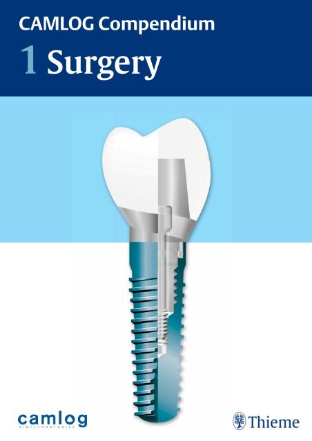
1 Surgery CAMLOG Compendium
1 Surgery CAMLOG Compendium
1 Surgery CAMLOG Compendium

You also want an ePaper? Increase the reach of your titles
YUMPU automatically turns print PDFs into web optimized ePapers that Google loves.
<strong>CAMLOG</strong> <strong>Compendium</strong><br />
1<br />
<strong>Surgery</strong>
<strong>CAMLOG</strong> <strong>Compendium</strong><br />
1 <strong>Surgery</strong><br />
All materials and dental procedures<br />
mentioned in this <strong>Compendium</strong> must<br />
be used and applied by qualified<br />
dentists and physicians only.<br />
The <strong>CAMLOG</strong> <strong>Compendium</strong> consists of<br />
two parts:<br />
1 <strong>Surgery</strong><br />
2 Prosthetics<br />
Single pages must not be distributed.<br />
Section Overview<br />
<strong>CAMLOG</strong> <strong>Compendium</strong> Part 1,<br />
<strong>Surgery</strong>:<br />
I. General system information<br />
II. <strong>CAMLOG</strong> concept<br />
Ill. Planning<br />
IV <strong>Surgery</strong> manual<br />
<strong>CAMLOG</strong> <strong>Compendium</strong> Part 2,<br />
Prosthetics:<br />
V. Prosthetics Manual<br />
<strong>CAMLOG</strong> <strong>Compendium</strong> | 1 <strong>Surgery</strong>
<strong>CAMLOG</strong> <strong>Compendium</strong> | 1 <strong>Surgery</strong><br />
Bibliographic information<br />
of the German Library<br />
The German Library catalogs this publication in the German<br />
National Bibliography; detailed bibliographic information can<br />
be found on the Internet website: http://dnb.ddb.de.<br />
All rights, including reprinting, reproduction in any form and<br />
translation into other languages, are reserved by the copyright<br />
holder and publisher. The manual may not be reproduced in<br />
whole or in part by photomechanical means (photocopy,<br />
microfiche) or stored, exploited systematically or distributed<br />
with electronic or mechanical systems without written<br />
approval from <strong>CAMLOG</strong> Biotechnologies AG.<br />
Authors:<br />
Axel Kirsch, Karl-Ludwig Ackermann,<br />
Rainer Nagel, Gerhard Neuendorff,<br />
Alexander Focke, Dieter Mozer,<br />
Alex Schär, Bernd Wagner<br />
Manufacturer:<br />
ALTATEC GmbH<br />
Maybachstrasse 5<br />
71299 Wimsheim, Germany<br />
Copyright © 2007 <strong>CAMLOG</strong> Biotechnologies AG<br />
Art. No.: J8000.0027 web version<br />
Printed in Germany<br />
Cover design: <strong>CAMLOG</strong> Team,<br />
Thieme Verlagsgruppe<br />
Printing/binding: Grammlich, Pliezhausen<br />
ISBN: 978-3-13-134351-2 1 2 3 4 5 6<br />
Important note: Like every field of science, medicine is undergoing<br />
continuous change. Research and clinical experience are<br />
continuously extending our knowledge, particularly of treatment<br />
and medicinal therapy. Where this publication refers to a<br />
dosage or administration, the reader can be assured that the<br />
authors, editor and publisher have taken great care to ensure<br />
that this information conforms to the state of the art at the<br />
time of publication.<br />
However, the publisher cannot accept any liability for information<br />
on dosage instructions and forms of administration. Every<br />
user is urged to check carefully the information in the package<br />
inserts of the medications and if necessary consult a specialist<br />
to see if the recommended dosage and administration or the<br />
observance of contra-indications is different from the information<br />
given in this book. It is particularly important to check<br />
this in the case of rarely used medications or those that have<br />
just been introduced to the market. Every dosage or administration<br />
is the sole responsibility of the user. The authors and<br />
the publisher request all users to inform the publisher of any<br />
inaccuracies.<br />
Protected brand names (trademarks) are not specially indicated.<br />
The absence of such indication does not mean that it is<br />
not a trademarked name.<br />
The publication with all its parts is protected by copyright.<br />
Any exploitation beyond the narrow limits of the copyright Act<br />
is not permissible without the approval of <strong>CAMLOG</strong><br />
Biotechnologies AG and is subject to legal sanctions.
Table of Contents<br />
I. General System Information 1. Introduction . . . . . . . . . . . . . . . . . . . . . . . . 1<br />
2. <strong>CAMLOG</strong> ® system - description . . . . . . . . . . 2<br />
3. Implant configuration . . . . . . . . . . . . . . . . 3<br />
Macroscopic shapes . . . . . . . . . . . . . . . . . . . . 3<br />
Internal and external configuration . . . . . . . . . . 4<br />
Bioseal Bevel / implant shoulder . . . . . . . . . . . 5<br />
Surfaces . . . . . . . . . . . . . . . . . . . . . . . . . . . . 6<br />
Tube-in-tube connection . . . . . . . . . . . . . . . . . 7<br />
Production precision . . . . . . . . . . . . . . . . . . . 8<br />
Materials . . . . . . . . . . . . . . . . . . . . . . . . . . . 8<br />
4. Mechanics and biomechanics . . . . . . . . . . . 9<br />
Mechanical studies . . . . . . . . . . . . . . . . . . . . . 9<br />
Lateral loading . . . . . . . . . . . . . . . . . . . . . . . . 9<br />
Failure loading . . . . . . . . . . . . . . . . . . . . . . . . 9<br />
Torsion loading . . . . . . . . . . . . . . . . . . . . . . . 10<br />
II. <strong>CAMLOG</strong> Concept 1. Team concept . . . . . . . . . . . . . . . . . . . . . . . 11<br />
The team . . . . . . . . . . . . . . . . . . . . . . . . . . . 11<br />
Team input . . . . . . . . . . . . . . . . . . . . . . . . . . 12<br />
2. Treatment concepts . . . . . . . . . . . . . . . . . . 13<br />
Introduction . . . . . . . . . . . . . . . . . . . . . . . . . 13<br />
Leverage relations at the implant . . . . . . . . . . . 13<br />
Esthetics . . . . . . . . . . . . . . . . . . . . . . . . . . . 14<br />
Patient cooperation . . . . . . . . . . . . . . . . . . . . 14<br />
Patient information . . . . . . . . . . . . . . . . . . . . 14<br />
Fixed dentures . . . . . . . . . . . . . . . . . . . . . . . . 15<br />
Single crowns . . . . . . . . . . . . . . . . . . . . . . . . 15<br />
Splinted crowns . . . . . . . . . . . . . . . . . . . . . . 16<br />
Implant-supported bridges . . . . . . . . . . . . . . . . 17<br />
Removable dentures . . . . . . . . . . . . . . . . . . . 18<br />
Telescopic crowns . . . . . . . . . . . . . . . . . . . . . . 18<br />
Bar abutment . . . . . . . . . . . . . . . . . . . . . . . . . 19<br />
Ball abutment . . . . . . . . . . . . . . . . . . . . . . . . 19<br />
III. Planning 1. Introduction . . . . . . . . . . . . . . . . . . . . . . . . 20<br />
2. Anamnesis . . . . . . . . . . . . . . . . . . . . . . . . . 21<br />
General . . . . . . . . . . . . . . . . . . . . . . . . . . . . 21<br />
Special (dental) . . . . . . . . . . . . . . . . . . . . . . . 21<br />
3. Examinations . . . . . . . . . . . . . . . . . . . . . . . 21<br />
Clinical . . . . . . . . . . . . . . . . . . . . . . . . . . . . 21<br />
Radiographic . . . . . . . . . . . . . . . . . . . . . . . . . 22<br />
Laboratory . . . . . . . . . . . . . . . . . . . . . . . . . . . 22<br />
<strong>CAMLOG</strong> <strong>Compendium</strong> | 1 <strong>Surgery</strong>
<strong>CAMLOG</strong> <strong>Compendium</strong> | 1 <strong>Surgery</strong><br />
4. Preliminary prosthetic design . . . . . . . . . . . 24<br />
Wax-up / set-up . . . . . . . . . . . . . . . . . . . . . . . 24<br />
Planning template . . . . . . . . . . . . . . . . . . . . . 25<br />
Radiographic template . . . . . . . . . . . . . . . . . . 26<br />
5. Implant position verification . . . . . . . . . . . 27<br />
Purpose . . . . . . . . . . . . . . . . . . . . . . . . . . . . 27<br />
Clinical . . . . . . . . . . . . . . . . . . . . . . . . . . . . 27<br />
Orthopantomography . . . . . . . . . . . . . . . . . . . 27<br />
Dental film . . . . . . . . . . . . . . . . . . . . . . . . . . 27<br />
Computer tomography with/without 3-D analysis 28<br />
Drilling template . . . . . . . . . . . . . . . . . . . . . . 28<br />
Final prosthetic design . . . . . . . . . . . . . . . . . . 29<br />
Customizing the prosthetic design . . . . . . . . . . 29<br />
Planning treatment procedures . . . . . . . . . . . . 29<br />
6. Recommended indications for various<br />
configurations . . . . . . . . . . . . . . . . . . . . . . 30<br />
IV. <strong>Surgery</strong> Manual 1. Preparation of the patient . . . . . . . . . . . . . 33<br />
2. Drilling template . . . . . . . . . . . . . . . . . . . . 33<br />
3. <strong>CAMLOG</strong> ® surgical system . . . . . . . . . . . . . 33<br />
Surgical sets . . . . . . . . . . . . . . . . . . . . . . . . . 34<br />
Drilling system . . . . . . . . . . . . . . . . . . . . . . . 37<br />
4. Healing options . . . . . . . . . . . . . . . . . . . . . 38<br />
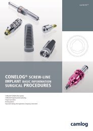
5. SCREW-LINE Implant . . . . . . . . . . . . . . . . . 39<br />
Introduction . . . . . . . . . . . . . . . . . . . . . . . . . 39<br />
Preparation of implant bed for<br />
SCREW-LINE Implants . . . . . . . . . . . . . . . . . . 44<br />
Implant package . . . . . . . . . . . . . . . . . . . . . . 54<br />
Implant insertion . . . . . . . . . . . . . . . . . . . . . . 56<br />
6. ROOT-LINE Implant . . . . . . . . . . . . . . . . . . . 65<br />
Introduction . . . . . . . . . . . . . . . . . . . . . . . . . . 65<br />
Preparation of implant bed for<br />
ROOT-LINE Implants . . . . . . . . . . . . . . . . . . . . 70<br />
Implant package . . . . . . . . . . . . . . . . . . . . . . 80<br />
Implant insertion . . . . . . . . . . . . . . . . . . . . . . 82
7. SCREW-CYLINDER-LINE Implant . . . . . . . . . 91<br />
Introduction . . . . . . . . . . . . . . . . . . . . . . . . . 91<br />
Preparation of implant bed for SCREW-<br />
CYLINDER-LINE Implants . . . . . . . . . . . . . . . . 96<br />
Implant package . . . . . . . . . . . . . . . . . . . . . .106<br />
Implant insertion . . . . . . . . . . . . . . . . . . . . . .108<br />
8. CYLINDER-LINE Implant . . . . . . . . . . . . . . .117<br />
Introduction . . . . . . . . . . . . . . . . . . . . . . . . . .117<br />
Preparation of implant bed for<br />
CYLINDER-LINE Implants . . . . . . . . . . . . . . . . .122<br />
Implant package . . . . . . . . . . . . . . . . . . . . . . .130<br />
Implant insertion . . . . . . . . . . . . . . . . . . . . . .132<br />
9. Healing caps . . . . . . . . . . . . . . . . . . . . . . .137<br />
Introduction . . . . . . . . . . . . . . . . . . . . . . . . .137<br />
Healing caps - cylindrical and wide body . . . . . .138<br />
Healing caps - bottleneck . . . . . . . . . . . . . . . .138<br />
Tissue augmentation/support . . . . . . . . . . . . .139<br />
10. Transfer system . . . . . . . . . . . . . . . . . . . . .140<br />
Introduction . . . . . . . . . . . . . . . . . . . . . . . . .140<br />
Closed tray impression method . . . . . . . . . . . . .141<br />
Open tray impression method . . . . . . . . . . . . .144<br />
11. Bite registration . . . . . . . . . . . . . . . . . . . .147<br />
12. Provisional solution . . . . . . . . . . . . . . . . . .148<br />
13. Torque wrench . . . . . . . . . . . . . . . . . . . . . .151<br />
Introduction . . . . . . . . . . . . . . . . . . . . . . . . .151<br />
Cleaning, sterilization, care . . . . . . . . . . . . . . .154<br />
14. Information . . . . . . . . . . . . . . . . . . . . . . . . .155<br />
Cleaning, sterilization . . . . . . . . . . . . . . . . . .155<br />
Information protocol . . . . . . . . . . . . . . . . . . .157<br />
Materials . . . . . . . . . . . . . . . . . . . . . . . . . . .158<br />
Certificates . . . . . . . . . . . . . . . . . . . . . . . . . .159<br />
<strong>CAMLOG</strong> <strong>Compendium</strong> | 1 <strong>Surgery</strong>
I. General System Information<br />
1. Introduction<br />
Modern implant prosthetics is now an<br />
established component of dentistry. The<br />
expectations and demands of patients<br />
are steadily increasing. Therefore, the<br />
ultimate goal of modern implant-supported<br />
treatment concepts is for full<br />
esthetic, functional, phonetic, and psychosocial<br />
rehabilitation. This applies<br />
equally to replacements of lost single<br />
incisors associated with trauma and the<br />
complex rehabilitation of periodontally<br />
compromised remaining teeth or the<br />
treatment of an edentulous heavily atrophied<br />
maxilla and mandible.<br />
This manual should help promote treatment<br />
success quickly, simply, and efficiently.<br />
The layout of this publication follows<br />
the logical sequence of planning<br />
and performance of a periodontal<br />
implant-supported prosthetic restoration.<br />
You get acquainted primarily with the<br />
configuration, mechanical, and biomechanical<br />
features of the implants, as well<br />
as with the innovative <strong>CAMLOG</strong> ®<br />
implant-to-abutment connection.<br />
Before presenting the prosthetic concepts,<br />
we give you an overview of the<br />
"backward planning" method and the<br />
team concept on which it is based, to<br />
ensure the best treatment result possible.<br />
The section Treatment Concepts provides<br />
an overview of the prosthetic<br />
options using the <strong>CAMLOG</strong> ® Implant<br />
System.<br />
The other sections follow the order of<br />
procedures suggested in the backward<br />
planning concept:<br />
• History, examination, diagnostics<br />
• Prosthetically oriented planning<br />
• Feasibility testing, adaptation,<br />
patient-oriented planning of the<br />
procedure sequence<br />
• <strong>Surgery</strong><br />
• Prosthetics<br />
• Follow-up<br />
General System Information<br />
Introduction<br />
Warning<br />
The descriptions that follow are not adequate<br />
to permit use of the <strong>CAMLOG</strong> ®<br />
Implant System immediately. Instruction<br />
by an experienced operator in the management<br />
of the <strong>CAMLOG</strong> ® Implant<br />
System is strongly recommended.<br />
<strong>CAMLOG</strong> ® dental implants and abutments<br />
should be used only by dentists,<br />
physicians, surgeons and dental technicians<br />
trained in the system. Appropriate<br />
courses and training sessions are regularly<br />
offered by <strong>CAMLOG</strong>.<br />
Methodological errors in treatment can<br />
result in loss of the implant and significant<br />
loss of peri-implant bone substance.<br />
1
General System Information<br />
<strong>CAMLOG</strong> ® System Description<br />
2. <strong>CAMLOG</strong> ®<br />
System Description<br />
The <strong>CAMLOG</strong> ® Implant System<br />
The <strong>CAMLOG</strong> ® Implant System is based<br />
on many years' clinical and dental technological<br />
experience. It is a user-friendly,<br />
logically prosthetic-oriented implant<br />
system. All <strong>CAMLOG</strong> ® products are<br />
continuously manufactured according<br />
to state of the art.<br />
The <strong>CAMLOG</strong> ® Implant System was further<br />
developed progressively through inhouse<br />
research and development in collaboration<br />
with hospitals, universities,<br />
and dental technicians. Today, it represents<br />
the state of the art in implant<br />
dentistry.<br />
In the recent past, science has become<br />
more and more important at <strong>CAMLOG</strong>.<br />
Today, the <strong>CAMLOG</strong> ® Implant System is<br />
scientifically very well documented. The<br />
system has been confirmed by numerous<br />
studies investigating into different<br />
parameters, e.g., implant surfaces, time<br />
of implantation and/or implant loading,<br />
primary stability, design of implant-abutment<br />
connection or type of superstructure.<br />
Long-term results of up to seven<br />
years for the <strong>CAMLOG</strong> ® Implant System<br />
are convincing.<br />
2
3. Implant<br />
Configuration<br />
Macroscopic Shapes<br />
All <strong>CAMLOG</strong> ® implants are equipped<br />
with the <strong>CAMLOG</strong> ® tube-in-tube<br />
implant-to-abutment connection. The<br />
four different external implant configurations<br />
have the same diameter-matched,<br />
internal configuration. This makes the<br />
use of different implant configurations in<br />
an arch possible without curtailment of<br />
the prosthesis (see also the recommended<br />
indications for the different implant<br />
types).<br />
SCREW-LINE Implant,<br />
Promote ®<br />
ROOT-LINE Implant,<br />
Promote ®<br />
General System Information<br />
Implant Configuration<br />
SCREW-LINE Implant,<br />
Promote ® plus<br />
SCREW-CYLINDER-LINE<br />
Implant, Promote ®<br />
CYLINDER-LINE<br />
Implant, TPS<br />
3
General System Information<br />
Implant Configuration<br />
External Configuration<br />
<strong>CAMLOG</strong> ® implants SCREW-LINE, ROOT-<br />
LINE and SCREW-CYLINDER-LINE with<br />
the Promote ® surface have a cylindrical<br />
machined portion 1.6 mm high in the<br />
coronal area (1). A rough machined<br />
chamfer - the Bioseal Bevel (height 0.4<br />
mm) - is attached to this apically (2).<br />
Below it is the self-tapping thread of the<br />
SCREW-LINE, ROOT-LINE or SCREW-<br />
CYLINDER-LINE implants (3) with the<br />
Promote ® surface. In the case of the<br />
CYLINDER-LINE implants, a TPS (titanium<br />
plasma-sprayed) surface is provided.<br />
Internal Configuration<br />
Starting from the coronal implant edge<br />
(4), all implants have three symmetrical<br />
grooves (width 0.5 or 0.7 mm, depth 1.2<br />
mm, 120° offset) in the upper cylindrical<br />
area (5). The abutment cams lock into<br />
these grooves. Beneath this area, an<br />
upper inner thread is found (6), on<br />
which the cover screw, healing caps,<br />
bar abutments, and male inserts of different<br />
prosthetic caps can be screwed.<br />
Apical to the thread is a short cylindrical<br />
part to which the abutment "tube" is<br />
attached (7). After another 60° offset,<br />
there follows apically a second inner<br />
thread (8) onto which the abutment<br />
screws M 1.6 or 2.0 are fastened.<br />
4<br />
1<br />
2<br />
3<br />
On the SCREW-LINE Implant with Promote ® plus<br />
surface, the machined part measures 0.4 mm.<br />
4<br />
5<br />
6<br />
7<br />
8
Bioseal Bevel/Implant Shoulder<br />
Following the protocol-conformal insertion<br />
of the implant, the implant shoulder<br />
lies approx. 0.4 mm above the bone level.<br />
Drilling irregularities between the<br />
implant drill hole and implant are totally<br />
excluded by the chamfer (Bioseal Bevel)<br />
beneath the implant shoulder which<br />
matches the profile of the drill hole.<br />
A biological width of approx. 2 mm<br />
remains (1 mm connective tissue adaptation<br />
and upon this an approx. 1-mm<br />
junction epithelial attachment) following<br />
protocol-conformal insertion of the<br />
implants with the Promote ® surface and<br />
TPS coating, and following exposure and<br />
a minor bone adaptation of approx.<br />
1 mm apically.<br />
SCREW-LINE Implants with Promote ®<br />
plus surface are likewise inserted so as<br />
to leave a 0.4 mm projection above the<br />
bone level. During the insertion and<br />
exposure, the periosteum should be<br />
removed only in the implant penetration<br />
area.<br />
Promote ® and TPS surface<br />
Promote ® plus surface<br />
General System Information<br />
Implant Configuration<br />
5
General System Information<br />
Implant Configuration<br />
Surfaces<br />
Promote ® and Promote ® plus<br />
Surface Structure<br />
Promote ® and Promote ® plus have an<br />
identical micro-macro surface structure,<br />
differing only in the vertical position<br />
of the rough/smooth boundary. The<br />
<strong>CAMLOG</strong> ® implants SCREW-LINE, ROOT-<br />
LINE and SCREW-CYLINDER-LINE are<br />
available with the Promote ® surface.<br />
Promote ® surface structure Laser scan of Promote ® surface Osteoblasts on a Promote ® surface<br />
Titanium Plasma-Sprayed<br />
Surface Structure<br />
The <strong>CAMLOG</strong> ® CYLINDER-LINE Implants<br />
have a titanium plasma-sprayed (TPS)<br />
surface in their endosseous portion,<br />
which has proven in long-term studies to<br />
be exceedingly reliable.<br />
Titanium plasma-sprayed surface structure<br />
6<br />
The <strong>CAMLOG</strong> ® SCREW-LINE implants are<br />
also available with the Promote ® plus<br />
surface, which has a machined part of<br />
only 0.4 mm in the coronal area.<br />
This sand-blasted, acid-etched surface<br />
has given excellent results in anchoring<br />
dental implants.<br />
Research results from cell cultures, bone<br />
histology, and extraction tests support<br />
this. The results suggest that the<br />
Promote ® surface promotes rapid<br />
osseointegration of the <strong>CAMLOG</strong> ®<br />
implants.
Tube-in-Tube Connection<br />
The long-term maintenance of periimplant<br />
soft and hard tissue health in<br />
implant-treated patients heavily depends<br />
on oral hygiene and pre-, intra-, and<br />
post-operative soft tissue management.<br />
The biomechanics of implant-supported<br />
restorations are controlled by the<br />
implant design and the components of<br />
the implant-abutment connection.<br />
Even if the number of implants is adequate<br />
and positioning is correct, a<br />
mechanically critical interface also exists<br />
between force application (through<br />
crown occlusion) and force absorption<br />
(by the ankylotic anchor in the bone) in<br />
the area of the implant-abutment connection.<br />
Numerous studies have shown that<br />
abutment screw loosening or fracture<br />
may occur here - even at submaximal<br />
load - depending on the implant-abutment<br />
connection used. Hence, the design<br />
of the implant-abutment connection is<br />
fundamentally important. Engineering<br />
science indicates the use of an connection<br />
with a diameter/insertion depth<br />
ratio greater than 1.4 for form-fit connection.<br />
The implant-abutment connection<br />
used in the <strong>CAMLOG</strong> ® System is a<br />
form-fit connection in which the diameter/insertion<br />
depth ratio is 1.5 to 2.4<br />
depending on the implant diameter.<br />
The design features of the patented<br />
<strong>CAMLOG</strong> connection result in improved<br />
results on statics strength and compression<br />
fatigue tests. To maintain these<br />
<strong>CAMLOG</strong> ® implant-abutment connection with abutment screw<br />
General System Information<br />
Implant Configuration<br />
levels and ensure long-term stability, the<br />
connection must never be modified for<br />
any reason!<br />
7
General System Information<br />
Production Precision<br />
Production Precision<br />
The internal and external geometry of the<br />
implants and abutments are machined,<br />
with the exception of the milled cams<br />
and grooves. This means that production<br />
tolerances can be kept very tight, and a<br />
precision fit with rotational stability<br />
(0.5°-1.0°) is ensured for all system<br />
components. This is an essential requirement<br />
in the fabrication of prosthetic<br />
restorations, starting with the transfer of<br />
the implant position to the master cast<br />
and continuing up to the final oral insertion.<br />
Materials<br />
All <strong>CAMLOG</strong> ® implants are made of<br />
pure grade 4 titanium. The abutments,<br />
caps, and abutment screws are made of<br />
titanium alloy Ti6AI4V (ASTM F136) (see<br />
Information - "Materials").<br />
8<br />
<strong>CAMLOG</strong> ® Implant<br />
Implant-abutment connection with<br />
abutment screw<br />
<strong>CAMLOG</strong> ® Abutment
4. Mechanics and<br />
Biomechanics<br />
Mechanical Tests<br />
Finite element models were prepared<br />
and the behaviors of different implantabutment<br />
connections were compared<br />
under vertical-lateral and torsional loading.<br />
The simulation was conducted using<br />
an FEM (finite element method) program<br />
(ASNSYS 3.3) at Offenbach Technical<br />
University.<br />
Lateral Loading<br />
The vector L of a load applied at 30° is<br />
divided into an axial force (Fa) and a<br />
lateral force (Fq). The axial component<br />
and lateral force must be compensated<br />
by the screw retention force as a function<br />
of the length of the lever from the<br />
fulcrum (D).<br />
Finite element studies show that when a<br />
vertical-lateral load is applied to the<br />
abutment, the forces are transmitted<br />
through the apical end of the tube to<br />
the implant body. Loading of the abutment<br />
screw hardly occurs.<br />
Failure Load<br />
Comparison of failure load (300 N at<br />
30°) in a 3.75 mm screw implant with<br />
an external hex connection clearly<br />
shows that the <strong>CAMLOG</strong> ® abutment<br />
screw is hardly stressed (blue = low<br />
strain, red = high strain).<br />
In the case of a force-based external hex<br />
connection, the Fa is ~5 Fq because of<br />
the lever ratio (the distance of the fulcrum<br />
from the middle of the axis is the<br />
implant radius).<br />
Force-based connection<br />
General System Information<br />
Mechanics and Biomechanics<br />
In the case of the form and force-based<br />
<strong>CAMLOG</strong> connection, the lateral component<br />
(Fq) is almost completely compensated<br />
by the supporting forces (F1 and<br />
F2) provided by the tube-in-tube connection.<br />
Because of the configuration of the<br />
tube-in-tube connection, the fulcrum<br />
location is practically on the midline of<br />
the implant. The lever length of the axial<br />
force component (Fa) is thereby reduced<br />
towards zero.<br />
Form and force-based connection<br />
External hex connection <strong>CAMLOG</strong> tube-in-tube connection<br />
9
General System Information<br />
Mechanics and Biomechanics<br />
Torsion Loading<br />
In the case of torque up to the moment<br />
the cams make contact in the implant,<br />
only the production clearance is considered,<br />
and therefore the repositioning<br />
accuracy of the abutment in the implant.<br />
The strain on the implant-abutment connection<br />
is very small (blue = low strain,<br />
red = high strain). The smaller the angular<br />
deflection, the more precise a position<br />
can be transfered.<br />
10<br />
Torsion [Nmm]<br />
Torsion behavior of the <strong>CAMLOG</strong> connection<br />
Angular deflection (°)
II. <strong>CAMLOG</strong> Concept<br />
1. Team Concept<br />
The Team<br />
Patient<br />
The patient must be fully informed about<br />
the options and limits of implant-supported<br />
rehabilitation in his or her particular<br />
case. The expectations and demands<br />
of the patient should be clearly formulated<br />
and documented.<br />
Dentist<br />
The restorative dentist providing prosthetic<br />
treatment is usually the team<br />
leader. His function is handling examinations,<br />
diagnostics, and treatment planning,<br />
and reaching a consensus for the<br />
treatment plan from the patient and<br />
possibly the surgeon and dental technician.<br />
He coordinates the prosthetic<br />
preparation while the surgeon plans and<br />
manages the treatment stages: surgical<br />
intervention, wound healing, and exposure.<br />
Surgeon<br />
The surgeon conducts a separate patient<br />
information session. He utilizes the diagnostic<br />
records, templates, medical/dental<br />
history, and radiographic information<br />
provided by the restorative dentist and<br />
dental technician. He performs the<br />
implantation procedures requested by<br />
the restorative dentist.<br />
Dental Technician<br />
The dental technician contributes his<br />
laboratory knowledge and experience to<br />
the preoperative planning of the<br />
implant-supported restoration. He prepares<br />
a setup/ wax-up, evaluates esthetic<br />
and functional issues, and makes suggestions<br />
for the design of the final<br />
restoration and implant positioning. His<br />
tasks include fabrication of the provisional<br />
and final restorations as well as<br />
provision of radiographic and drilling<br />
templates and he selects the implant<br />
abutments.<br />
Dental Hygienist/Nurse/Assistant<br />
An important prerequisite for the longterm<br />
success of a dental implant is<br />
excellent oral hygiene. The dental<br />
hygienist/nurse/assistant explains correct<br />
oral hygiene to the patient and takes the<br />
preparatory steps to create an inflammation-free<br />
oral situation. She is also<br />
responsible for ensuring regular followup<br />
appointments.<br />
<strong>CAMLOG</strong> Concept<br />
Team Concept<br />
<strong>CAMLOG</strong><br />
<strong>CAMLOG</strong> supports all members of the<br />
implant treatment team by providing<br />
high product quality, information,<br />
service, continuing education, and<br />
continuous research and development<br />
of the <strong>CAMLOG</strong> ® Implant System.<br />
11
<strong>CAMLOG</strong> Concept<br />
Team Concept<br />
Team Input<br />
Increasingly higher demands for quality<br />
and specialization require a multidisciplinary<br />
team approach to combine the<br />
members' acquired knowledge and experience.<br />
Modern implant-supported<br />
restorations need a high level of attention<br />
to detail and clinical experience.<br />
This is true equally for the restorative<br />
dentist, the surgeon, the dental technician,<br />
and the dental office support staff<br />
such as the nurse, hygienist, and chair<br />
assistant. The <strong>CAMLOG</strong> team concept<br />
takes all of these demands into consideration.<br />
The sequence of treatment procedures<br />
is structured, and specific procedures<br />
are clearly assigned to specific<br />
team members once the joint planning<br />
phase is complete. Pre-implantation surgical<br />
interventions and the implantation<br />
itself are carried out by the surgeon, or<br />
a surgically qualified restorative dentist.<br />
The surgical instrumentation should be<br />
simply and thoughtfully organized. If a<br />
transgingival implantation (one-step) is<br />
to be performed, this eliminates a second<br />
intervention (implant exposure). In<br />
contrast, if a covered implantation is<br />
selected (two-step), a healing cap must<br />
be attached for soft tissue conditioning<br />
for three weeks after the exposure and<br />
before taking the impression, depending<br />
on the indications. The dentist/surgeon<br />
takes the impression using the transfer<br />
system and an impression material of<br />
choice (silicone, polyether, etc.). In addition<br />
to the impression components, only<br />
a screwdriver is required.<br />
12<br />
The implant-abutment selection is made<br />
after the master cast has been fabricated<br />
in the laboratory.<br />
Because of the high precision of the<br />
implant components and the rotational<br />
stability of the implant-to-abutment connection,<br />
time-consuming intermediate<br />
try-ins can be skipped. Both dentist and<br />
dental technician can concentrate on<br />
esthetics and the hygienic adaptability<br />
of the restoration because the insertion<br />
of the abutment is so simple and quick.<br />
Single-crown restorations, small bridges,<br />
bar abutments with the <strong>CAMLOG</strong> passive-fit<br />
system, and telescopic crowns<br />
can be fabricated to offer a perfect fit.<br />
The <strong>CAMLOG</strong> ® Implant System is therefore<br />
user-friendly and time-saving. The<br />
scope and value of pre-implantation<br />
diagnostics have changed. Today, preimplantation<br />
diagnostics must be oriented<br />
exclusively to prosthetic needs (backward<br />
planning).<br />
Since implant-supported treatment success<br />
is judged almost entirely in terms of<br />
esthetics and function, no prior compromises<br />
in these areas should ever be considered.<br />
The objective is to obtain a<br />
patient-oriented total rehabilitation.<br />
Sequence of Treatment Procedures<br />
• Planning Team<br />
• Pre-treatment Dentist (surgeon, if needed)<br />
dental support staff, hygienist<br />
• Implantation Dentist (surgeon, if needed)<br />
• Impression taking Dentist (surgeon, if needed)<br />
• Cast fabrication Dental technician<br />
• Plan review, abutment selection Dentist, dental technician<br />
• Prosthesis fabrication Dental technician<br />
• First bake (esthetics) try-in Dentist, dental technician<br />
• Finishing Dental technician<br />
• Prosthesis insertion Dentist<br />
• Maintenance/recall Dentist, support staff
2. Treatment Concept<br />
Introduction<br />
It is known from general physiology that<br />
both non-loading and underloading of<br />
the bone induces degradation just as<br />
much as overloading (inactivity atrophy,<br />
pressure atrophy). The area between<br />
these two extremes is called normal<br />
loading. This consists in a balance<br />
between growth and degradation.<br />
Working with bridge restorations in conventional<br />
prosthetics has led to identification<br />
of consistently high rates of bone<br />
degradation in non-loaded or underloaded<br />
abutment teeth (Misch/Frost<br />
1990).<br />
W. Schulte recognized this in 1982 and<br />
proposed early (= immediate, if possible)<br />
implantation to offset atrophy of the<br />
periodontal structures, which commences<br />
immediately after tooth loss. The implant<br />
supports the alveolar bone and tooth-bytooth<br />
implant-supported rehabilitation<br />
prevents the bony areas from being<br />
either overloaded or subjected to inactivity<br />
atrophy (stress-shielding).<br />
References<br />
Frost HM. Bone "mass" and the<br />
"mechanostat": a proposal. Anat Rec<br />
1987; 219:1-9<br />
Misch CE. Contemporary implant dentistry.<br />
St Louis. Mosby Inc. 1999;<br />
Ch.22:317-318<br />
Schulte W. Das Tübinger Implantat.<br />
Schweiz Mschr Zahnmed 1985; 95:872-<br />
874<br />
Leverage Relations at the Implant<br />
Loading of the implant-bone interface is<br />
a result of the leverage relation generated<br />
by osseointegration-related resistance<br />
to the prosthesis load arm (equivalent to<br />
the supracrestal implant length plus the<br />
height of the crown above the implant<br />
shoulder). If this (IL) is less than 1 (CL),<br />
then the load must be reduced (e.g.,<br />
through prosthetic splinting).<br />
<strong>CAMLOG</strong> Concept<br />
Treatment Concept<br />
13
<strong>CAMLOG</strong> Concept<br />
Treatment Concept<br />
Esthetics<br />
The use of therapeutic methods from an<br />
esthetic perspective is very dependent<br />
upon the initial situation and the visibility<br />
of the esthetic impairment. In the<br />
"esthetic zone" (anterior maxillary<br />
area), the smile line (as described by<br />
Kois) determines the extent of work that<br />
may be necessary. If prominent transversal<br />
or vertical hard or soft tissue deficits<br />
are present that affect the extraoral soft<br />
tissue profile, then lip and cheek support<br />
will have to be provided through suitable<br />
augmentative methods such as<br />
implant positioning or prosthesis design.<br />
These can restore the patient's physiognomy<br />
to a large extent.<br />
14<br />
Low smile Line<br />
The patient exhibits:<br />
Fixed Restorations<br />
Single Crowns<br />
Single crown treatment in the form of<br />
tooth-by-tooth restorations is the desirable<br />
and ideal form of treatment for the<br />
purpose of a complete oral makeover. It<br />
contains all the beneficial elements of<br />
periodontal prosthetic rehabilitation:<br />
• Physiologically adequate, biomechanical<br />
loading prevents further atrophy of<br />
the hard and soft tissue.<br />
• Good preconditions for natural-looking<br />
esthetics are established.<br />
• Oral hygiene is simple.<br />
• Fabrication is technically straightforward.<br />
• Readily extendable/alterable.<br />
• Maintenance is easy.<br />
• Economical for the patient in the middle<br />
and long term. In the event of further<br />
tooth loss, no new construction is<br />
necessary, just extension.<br />
Esthetically difficult Areas<br />
To achieve an esthetically successful<br />
restoration, a number of important elements<br />
are required: a harmonious gingival<br />
line, optimal implant positioning on<br />
both vertical and horizontal planes, a<br />
natural-looking crown shape, and the<br />
presence of interdental papillae. The<br />
indications for the hard tissue configurations<br />
to be preserved and for soft tissue<br />
management must be observed during<br />
planning. Structure-preserving or structure-sparing<br />
procedures must be used<br />
during flap creation and implant placement.<br />
In addition, oral hygiene requirements<br />
must be kept in mind during planning.<br />
Vertical implant position<br />
Mesiodistal implant position at bone level Distance to bone level<br />
Objective<br />
Single crowns (tooth-by-tooth treatment)<br />
provide the ideal restoration in terms of<br />
biomechanical, esthetics, hygiene,<br />
tongue comfort, and muscular balance.<br />
They prevent inactivity atrophy of the<br />
bone surrounding the implant through<br />
physiological loading.<br />
<strong>CAMLOG</strong> Concept<br />
Treatment Concept<br />
15
<strong>CAMLOG</strong> Concept<br />
Treatment Concept<br />
Splinted Crowns<br />
In the event of unfavorable leverage<br />
relations around the implant, a choice<br />
must be made between a longer implant<br />
or, if this is anatomically impossible,<br />
splinting adjacent crowns. If splinting is<br />
required by reason of statics, then<br />
hygienic requirements must also be<br />
taken into account.<br />
Development of a uniform insertion<br />
direction for the crown block should be<br />
part of the abutment preparation. The<br />
implant-to-abutment connection should<br />
not be altered.<br />
16<br />
Single-crown restoration<br />
Crown splinting<br />
Single-crown restoration in the<br />
augmented maxillary posterior area<br />
Crown splinting in the augmented maxillary<br />
posterior area
Implant-Supported Bridges<br />
Implant-supported bridges can be inserted<br />
wherever an implantation is impossible.<br />
Implant distribution should be structured<br />
in such a way that spanned<br />
segments are kept small.<br />
Development of a uniform insertion<br />
direction for the crown block should be<br />
part of the abutment preparation. The<br />
implant-to-abutment connection should<br />
not be altered.<br />
Examples of bridge positioning<br />
Initial situation<br />
Abutments in a lab analog<br />
Prepared abutments Cemented bridge<br />
<strong>CAMLOG</strong> Concept<br />
Treatment Concept<br />
17
<strong>CAMLOG</strong> Concept<br />
Treatment Concept<br />
Removable Restorations<br />
Introduction<br />
A hybrid denture may be implantretained,<br />
mucosa-supported, or implantsupported.<br />
The tension-free seat of a<br />
secondary (telescopic crown) or primary<br />
(bar) splinted structure on implants is<br />
called as "passive fit".<br />
Telescopic Crowns<br />
The production precision of the <strong>CAMLOG</strong><br />
connection is particularly necessary with<br />
a telescopic crown restoration since the<br />
abutments can be fastened always in the<br />
same, exactly defined position on the<br />
implant. A precision fit for the removable<br />
superstructure is made simple and consistent<br />
in every case.<br />
Indication: The telescopic crown technique<br />
is suitable for jaw relations in<br />
Angle Classes I and III.<br />
18<br />
In the case of telescopic crowns, this is<br />
obtained through intraoral bonding of<br />
the secondary crowns (preferably galvano<br />
crowns) onto the tertiary framework.<br />
In the case of bar structures, it<br />
involves the use of bar sleeves for a passive<br />
fit and intraoral bonding of the titanium<br />
bonding base.<br />
The idea is to create a fit that is free<br />
from stress or to minimize stress on the<br />
implants. In the planning of a removable<br />
denture the implants should be placed<br />
so that, if necessary, a tooth-by-tooth<br />
restoration or a fixed restoration is possible.
Bar supported Dentures<br />
Bars are suitable for jaw relations in<br />
Angle Class II and for large horizontal<br />
deficits. It may be possible to fabricate a<br />
bar structure with either prefabricated or<br />
individualized components.<br />
Ball Abutments<br />
The ball abutment is suitable for simple,<br />
implant-retained prosthetic restorations.<br />
It is simply a retainer, but positional stability<br />
can be created through addition of<br />
an extension prosthesis.<br />
<strong>CAMLOG</strong> Concept<br />
Treatment Concept<br />
19
Planning<br />
General Information<br />
III. Planning<br />
1. Introduction<br />
Modern implant prosthetics is planned<br />
by working back from the desired therapy<br />
goal; this is referred to as "backward<br />
planning." It applies particularly to preimplantation<br />
augmentation procedures<br />
to restore sufficient bony structure to<br />
allow placement of implants in the optimal<br />
prosthetic position.<br />
Overview<br />
A planning project may be divided into the following modules:<br />
• Actual situation / prosthetic<br />
initial situation<br />
Find out and document the actual situation<br />
by taking a general and special<br />
(dental) history and performing intraand<br />
extraoral clinical, functional and<br />
radiographic examinations. Together,<br />
these findings are the basis for a<br />
description of the initial situation of<br />
the oral-maxillofacial system.<br />
• Individual treatment goal<br />
A full analysis is conducted with the<br />
patient, including a cost/benefit,<br />
work/benefit, and risk/benefit analysis.<br />
The final result will be a treatment<br />
goal customized to the desires and<br />
options of the patient.<br />
20<br />
Function, phonetics, and hygienic potential<br />
require prosthetically oriented<br />
implant positioning and dimensioning,<br />
which the dental technician defines on<br />
the basis of the wax-up. The prosthetic<br />
design and the required implant position(s)<br />
and axial alignment(s) are<br />
planned by the dentist and dental technician<br />
working closely together. This<br />
requires both to be fully informed of the<br />
treatment options.<br />
• Ultimate treatment goal<br />
An ultimate treatment goal is defined<br />
by integrating the diagnosis, needs,<br />
patient's wishes for esthetics and<br />
function, and findings from the waxup/set-up.<br />
• Treatment sequence<br />
With the individualized treatment<br />
goal as guide, prosthetically oriented<br />
implant positioning is defined and<br />
verified clinically and radiographically.<br />
Then, a treatment sequence is set up.<br />
It includes the planning of ancillary<br />
procedures, augmentation, and any<br />
required pretreatment.<br />
If implant positions (implants approximating<br />
the former tooth positions) cannot<br />
be implemented for a fixed denture<br />
for whatever reason – functional<br />
(implant loading, crown length), esthetic<br />
(soft tissue support) or hygienic – a<br />
removable denture must be planned.
2. Anamnesis<br />
Introduction<br />
The medical history and diagnosis are<br />
not different from the evaluation procedures<br />
required for other dental surgery<br />
or restorative treatments. For this reason<br />
only the specific points for perio-implant<br />
prosthetic treatments are described<br />
below.<br />
The general, social and special (dental)<br />
medical history considers all general<br />
medical contraindications and diseases<br />
that could affect the microcirculation or<br />
the patient's suitability for the proposed<br />
implant-based restoration. Risk factors<br />
such as nicotine, alcohol and drug abuse<br />
are confidentially evaluated, discussed<br />
and documented.<br />
The patient's psycological and psychosocial<br />
situation gives an indication of the<br />
compliance that can be expected and<br />
will influence the planning of the treatment<br />
and the future prosthetic design.<br />
General<br />
The general medical history should<br />
include not only the disease history but<br />
also regular medication usage and the<br />
possibility of general medical problems<br />
that could adversely affect an implantbased<br />
prosthetic treatment.<br />
Special (dental)<br />
The special medical history must clarify<br />
the reasons for the current situation of<br />
the oral system.<br />
It may provide information on systemic<br />
diseases that may not have been detected<br />
yet. If implants or grafts were previously<br />
placed this may be important for<br />
assessment of the bone quality.<br />
3. Examinations<br />
Clinical<br />
In addition to all standard extraoral<br />
examinations, the soft tissue profile and<br />
support of the soft tissues (especially in<br />
the maxilla) are a critical factor in<br />
designing the prosthesis. If a large discrepancy<br />
exists between the required<br />
labial tooth position and the proposed<br />
implant position, the use of a removable<br />
denture (bar-structure, telescopic crown,<br />
ball abutment, Locator ® ) may be necessary<br />
for loading reasons.<br />
The results of the intraoral examinations<br />
determine which teeth can be saved. The<br />
standard of hygiene is evaluated and a<br />
check of the soft tissue for pathological<br />
conditions is performed for information<br />
on the patient's possible compliance<br />
during and after treatment.<br />
The static and dynamic occlusion, interalveolar<br />
distance, and centric relations<br />
are checked. Temporomandibular joint<br />
disorders are addressed before the start<br />
of treatment.<br />
All findings indicating elevated stress on<br />
the masticatory system (e.g., bruxism)<br />
must be investigated, documented, and<br />
considered in the prosthetic planning.<br />
The status of the soft tissue in edentulous<br />
arch segments (width and thickness<br />
of the attached gingiva) must be<br />
checked and the extension of the alveolar<br />
ridge must be evaluated for its suitability<br />
as a possible implant site.<br />
Planning<br />
General Information<br />
21
Planning<br />
General Information<br />
Radiographic Evaluation<br />
Dental x-rays<br />
Dental x-rays are sufficient for the initial<br />
assessment of bone supply with single<br />
tooth gaps or small interdental gaps. The<br />
periodontic situation of the remaining<br />
dentition must be closely examined,<br />
because the implant site may be colonized<br />
by pathogenic organisms from<br />
infected pockets.<br />
Orthopantomograph<br />
An OPG is a critical instrument for gathering<br />
basic information. Additional data<br />
required by the specific situation may be<br />
obtained through dental x-rays, remote<br />
x-ray side views, or computer-tomographic<br />
scans (CT).<br />
Remote x-ray side View<br />
Use for large sagittal differences and<br />
planned bone removal in the chin<br />
region.<br />
Computer-Tomographic Scan<br />
The CT is an instrument to be used for<br />
extensive radiological diagnostics. It<br />
enables a 3-D evaluation of the site<br />
from its anatomical structures and the<br />
planning of augmentations. Indications<br />
must be strictly adhered to because of<br />
the level of radiation exposure involved.<br />
22<br />
Laboratory<br />
Cast Analysis<br />
It is essential to mount a diagnostic cast<br />
in an adjustable articulator to assess jaw<br />
relations. Specifically, a check should be<br />
made whether a change of the<br />
occlusal position is worthwhile or<br />
required. If at all possible, it should be<br />
done before the actual implant-supported<br />
prosthetic treatment gets under way.<br />
In any case, a change in occlusal height<br />
must be preceded by treatment with a<br />
long-term provisional.<br />
Diagnostic Casts<br />
The diagnostic casts must clearly show<br />
not only the occlusal surfaces but also<br />
the vestibular fold and retromolar areas<br />
(see arrows).<br />
Diagnostic casts for implant planning are<br />
made of super-hard dental stone, just as<br />
in perioprosthetics, and mounted on an<br />
adjustable articulator with an arbitrary<br />
face bow and centrics registration. The<br />
centric registration must be freely<br />
adjustable to enable the casts to be<br />
mounted in correct axial alignment and<br />
position.<br />
The impression should reproduce the<br />
soft tissue situation and any hard or soft<br />
tissue deficits as far as the vestibular<br />
fold, since it is here we detect the first<br />
indications to incline the implant or the<br />
necessity for bone augmentation. Just as<br />
in perioprosthetics, the retromolar areas<br />
must be reproduced to allow specification<br />
of the dental arch and assessment<br />
of the vertical space available (see<br />
arrows).<br />
Planning and implementation of periodontal<br />
implant-supported rehabilitation<br />
will be considerably simplified if templates<br />
are used.
Articulator Set-Up<br />
The diagnostic casts are mounted in an<br />
adjustable articulator with the aid of an<br />
arbitrary face bow and centric registration<br />
as in perioprosthetics.<br />
Occlusal Height<br />
If an occlusal height requires correction,<br />
this must be done with a guard or longterm<br />
provisional before the implant-supported<br />
prosthetic restoration begins.<br />
Initial Prosthetic Situation<br />
The initial prosthetic situation describes<br />
the dental status, arch relations, the<br />
anatomical status of the oral hard tissue,<br />
the intraoral and extraoral soft tissue,<br />
the presence of functional, phonetic and<br />
esthetic restrictions on the patient, and<br />
the resulting influence on the patient's<br />
quality of life.<br />
Arch Relations (transversal)<br />
The arch relations control the load direction<br />
and therefore the axial alignment of<br />
the implants also. This is particularly<br />
important with cross-bite situations.<br />
Planning<br />
General Information<br />
Arch Relations (sagittal)<br />
Crowns cannot be placed precisely over<br />
the implants in the presence of Angle<br />
Class II dentition because the soft tissues<br />
must be supported and the space<br />
for the tongue must not be reduced. A<br />
removable denture is indicated in this<br />
situation.<br />
23
Planning<br />
General Information<br />
4. Preliminary<br />
Prosthetic Design<br />
Wax-Up/Set-Up<br />
The wax-up or set-up is prepared on the<br />
working cast in the dental laboratory.<br />
This permits planning of optimal tooth<br />
positioning from both functional and<br />
esthetic perspectives. It also enables early<br />
recognition of the need for augmentation<br />
procedures if a discrepancy is<br />
detected between the atrophied crestal<br />
bone and the required position for a<br />
prosthetic crown.<br />
The ideal articulation pattern to aim at<br />
is a situation-adapted anterior-to-cuspid<br />
line with early disclusion of the posteriors<br />
("freedom in centric" should be possible).<br />
24<br />
Initial Situation<br />
Wax-Up/Set-Up
Planning Template<br />
A planning template is fabricated to<br />
review the planned implant positions in<br />
the mouth. The template can be converted<br />
to a drilling template later.<br />
The dental technician initially fabricates<br />
a complete wax-up/set-up with all missing<br />
teeth in their ideal prosthetic position<br />
for preliminary planning of the prosthetic<br />
design. In accordance with the<br />
"backward planning" principle, any<br />
anatomical deficits are not considered at<br />
this stage. The treatment goal specifies<br />
the surgical and prosthetic procedure.<br />
A silicone index is fabricated from this<br />
set-up. After hardening, the index is<br />
divided orally along the central occlusion<br />
to form a labial and an oral section. An<br />
acrylic template can be fabricated with<br />
the aid of the silicone index.<br />
Alternatively, the work can be done with<br />
a rigid vacuum foil via a duplicate cast.<br />
Depending on the x-ray methods, radioopaque<br />
markers (e.g., titanium, steel,<br />
barium sulfate) are integrated.<br />
Silicone Index<br />
Cast with Planning Template<br />
Planning<br />
General Information<br />
25
Planning<br />
General Information<br />
X-Ray Template<br />
In the planning template or base produced<br />
from the wax-up/set-up, CT-planning<br />
tubes or other radio-opaque markers<br />
are integrated at the ideal<br />
implantation position and are used as<br />
reference positions in the x-ray image.<br />
The tubes consist of two parts: The titanium<br />
used leaves no scattering on CT<br />
scans. The lower part is polymerized in<br />
the template and the upper part inserts<br />
into this. The complete tube is used in<br />
radiologic diagnostics, and the upper<br />
part can be removed during surgery.<br />
Titanium tubes for CT-planning or other<br />
radio-opaque positioning components<br />
(steel, barium sulfate) are integrated,<br />
depending on the analysis software. If<br />
the tubes are placed directly on the<br />
mucous membrane, its thickness can be<br />
detected on the CT scan. For more information,<br />
see the documentation for these<br />
systems.<br />
26<br />
CT-tubes for CT-planning<br />
for drills Ø 2.0 mm:<br />
Inner Ø 2.1 mm<br />
Outer Ø 2.5 mm<br />
Planning template with tubes for CT planning<br />
X-ray template, outlined with tubes<br />
Drill for CT-tube<br />
placement<br />
Template without tube upper section for use as<br />
a drilling template<br />
X-ray template with radio-opaque teeth and<br />
installed tubes
5. Implant Position<br />
Verification<br />
Goal<br />
The goal is to specify the possible<br />
implant positions. Now, the final implant<br />
planning is performed depending on the<br />
selected concept. The x-ray images must<br />
show calibrated measurement points to<br />
enable measurement of the bone volume<br />
available for the implantation.<br />
Orthopantomogram<br />
Planning films are available in 1:1.25<br />
and 1:1.4 sizes for all implant types to<br />
check the dimensions on the OPG. The<br />
film magnifications match the magnification<br />
factors for most OPGs. However,<br />
they should be considered only as<br />
approximations in implant dimensioning.<br />
Dental Film<br />
To check the dimensions on x-ray film,<br />
the self-adhesive implant planning films<br />
(x-ray transfer pictures) for the specific<br />
implant type should be attached to the<br />
proposed implant positions on the film.<br />
Clinical<br />
The wax-up or set-up must be tried in on<br />
the patient. This allows esthetics to be<br />
included in the plan, such as the smile<br />
line, tooth shade, facial shape and general<br />
presentation of the patient.<br />
Planning<br />
General Information<br />
27
Planning<br />
General Information<br />
CT Scan with/without 3-D<br />
Evaluation<br />
A precise three-dimensional evaluation<br />
of the bone dimensions is possible only<br />
with a CT scan. Simulation programs can<br />
be used for computer-supported evaluation.<br />
Special conditions such as septation<br />
or infections in planned sinus-floor<br />
elevations and critical vertical relations<br />
in the mandible can be recognized.<br />
Depending on the program, the template<br />
must include radio-opaque position<br />
markers (titanium balls, titanium tubes,<br />
barium sulfate coating).<br />
28<br />
The medical information derived from<br />
the x-ray template can be used to determine<br />
the bone volume and quality with<br />
the aid of a CT scan and 3-D evaluation<br />
and this will define the subsequent therapy<br />
procedure (number of implants,<br />
implant position, implant diameter, and<br />
implant length).<br />
The final prosthetic design and the hard<br />
and soft tissue augmentation, if required,<br />
are discussed with the patient on the<br />
basis of this information and approved.<br />
Drilling Template<br />
Using this radiographic information, the<br />
planned implant positions are checked<br />
and adjusted if necessary. The x-ray template<br />
is thereby converted to a drilling<br />
template. The positions of the titanium<br />
tubes are modified or specified in the<br />
template. In consultation with the surgeon,<br />
the template is reduced to an<br />
outline after preparation of the flap to<br />
ensure it stays in position during surgery,<br />
i.e., stability requires a dental or gingival<br />
base outside the planned surgical<br />
field.<br />
View of the cast positioning X-ray templates in situ 3-D planning of implant positions<br />
View of the cast positioning X-ray templates in situ 3-D planning of implant positions
Final Prosthesis Design<br />
The surgical feasibility of the treatment<br />
sequence is checked with reference to<br />
the initial situation, the casts, and the<br />
x-ray findings. Depending on the clinical<br />
situation, periodontal or augmentation<br />
interventions are performed before<br />
implant surgery or at the time of the<br />
implant placement.<br />
Individualization of the Prosthetic<br />
Design<br />
The patient's wishes regarding the scope<br />
and cost of the implant-supported prosthetic<br />
restoration expressed in the<br />
patient interview are incorporated into<br />
the individual prosthesis design. The<br />
number of implants, the requirement for<br />
augmentation and possible soft-tissue<br />
corrections are determined exclusively by<br />
local conditions and the prosthetic<br />
design. This interview must be documented<br />
in detail and the patient must<br />
sign a statement of consent before<br />
implementing the treatment process.<br />
Planning the Treatment Sequence<br />
Now that the prosthetic goal has been<br />
defined, the required treatment steps are<br />
specified in a backward planning<br />
process. This process must include all<br />
details that are likely to be required,<br />
particularly in connection with augmentation.<br />
The planning template can now<br />
be converted into a drilling template.<br />
Documentation of Patient Interview and Explanation<br />
The results of the planning process are discussed with the patient. Casts, x-ray<br />
images, and the planning devices (wax-up and set-up) are helpful, here.<br />
The following criteria are considered:<br />
• Initial situation<br />
• Desires and expectations regarding esthetics, function and comfort<br />
• Effort/benefit ratio<br />
• Costs<br />
• Risk<br />
• Duration of treatment<br />
• Restrictions in comfort during treatment<br />
Planning<br />
General Information<br />
29
Planning<br />
Recommended Indications<br />
6. Recommended<br />
Indications for the<br />
Different Implant<br />
Configurations<br />
<strong>CAMLOG</strong> ® implants are endosseous<br />
implants, available in different lengths<br />
and configurations. They are placed surgically<br />
in the maxillary and/or mandibular<br />
bone and serve as anchors for functional<br />
and esthetic oral rehabilitations in<br />
partial or fully edentulous patients.<br />
Prosthetic treatments include single<br />
crowns, bridges, partial or full dentures<br />
attached to <strong>CAMLOG</strong> ® implants through<br />
suitable connection elements. Generally<br />
there are no preferred sites for the use<br />
of the different implant geometrys.<br />
An independent selection of implants<br />
according to the surgical situation is<br />
possible because the diameter-specific<br />
prosthetic platform is identical for all<br />
implant configurations. Different implant<br />
types can be used in the same arche.<br />
30<br />
SCREW-LINE Implant<br />
Both Promote ® and Promote ® plus<br />
SCREW-LINE Implants are universally<br />
applicable.<br />
ROOT-LINE Implant<br />
The ROOT-LINE Implant (with Promote ®<br />
surface) is a root-shaped, screw-type<br />
implant and is specifically indicated in<br />
conditions of apically reduced bone supply<br />
(canine fossa, apically on the mylohyoid<br />
line). The root-shaped design is<br />
particularly advantageous in the presence<br />
of root convergence from adjacent<br />
teeth.
SCREW-CYLINDER-LINE Implant<br />
The SCREW-CYLINDER-LINE Implant<br />
(with Promote ® surface) is particularly<br />
suitable for restorations in structurally<br />
weak sites on the posterior maxilla. In<br />
conjunction with sinus floor elevation<br />
and augmentation, its segmentally<br />
threaded configuration permits use of<br />
the residual crestal bone height (>5<br />
mm) to stabilize the implant. The cylindrical<br />
apical segment preserves the sinus<br />
mucosa during insertion of the implant<br />
(no thread edges) and provides superior<br />
adaptation to the particular bone augmentation<br />
material used.<br />
CYLINDER-LINE Implant<br />
CYLINDER-LINE Implants (with TPS surface)<br />
are universally applicable. A particular<br />
advantage of this implant type is its<br />
simple, time-saving application procedure.<br />
In conjunction with sinus floor elevation<br />
and augmentation, the press-fit<br />
from the cylindrical configuration of the<br />
implant allows it to be placed in a structurally<br />
weak site with a residual bone<br />
height
IV. <strong>Surgery</strong> Manual<br />
1. Preparation of the Patient<br />
The patient is prepared according to the<br />
standard routine for a surgical intervention.<br />
Depending on the indication,<br />
antibiotics and anti-inflammatories may<br />
be administered before and/or after surgery.<br />
In addition, an oral or intravenous<br />
sedative may be indicated depending on<br />
the patient's history and general health<br />
status.<br />
2. Drilling Template<br />
Before using a drilling template, it is<br />
necessary to check its outline for the<br />
planned incision line and to disinfect the<br />
template. The drilling template must also<br />
be reproducible after the flap preparation<br />
by remaining stable in place, and<br />
must adhere to the soft tissue without<br />
pressure.<br />
3. <strong>CAMLOG</strong> ® <strong>Surgery</strong> System<br />
All the drills, drivers, and accessories<br />
required for the implantation of the particular<br />
implant configuration are systematically<br />
organized in the <strong>Surgery</strong> Set. The<br />
sequence of use of the drills and instruments<br />
in compliance with the <strong>CAMLOG</strong><br />
surgical protocol is color-coded according<br />
to diameter. The following <strong>Surgery</strong><br />
Sets with their matching drills are available:<br />
• SCREW-LINE<br />
• ROOT-LINE<br />
• SCREW-CYLINDER-LINE/CYLINDER-<br />
LINE<br />
Color Coding<br />
Ø 3.3 mm grey<br />
Ø 3.8 mm yellow<br />
Ø 4.3 mm red<br />
Ø 5.0 mm blue<br />
Ø 6.0 mm green<br />
<strong>Surgery</strong> Manual<br />
Introduction<br />
33
<strong>Surgery</strong> Manual<br />
<strong>CAMLOG</strong> ® <strong>Surgery</strong> System<br />
SCREW-LINE <strong>Surgery</strong> Set<br />
34<br />
SCREW-LINE
ROOT-LINE <strong>Surgery</strong> Set<br />
ROOT-LINE<br />
<strong>Surgery</strong> Manual<br />
<strong>CAMLOG</strong> ® <strong>Surgery</strong> System<br />
35
<strong>Surgery</strong> Manual<br />
<strong>CAMLOG</strong> ® <strong>Surgery</strong> System<br />
SCREW-CYLINDER-LINE/CYLINDER-LINE <strong>Surgery</strong> Set<br />
SCREW-CYLINDER-LINE/CYLINDER-LINE<br />
36
Drilling System<br />
Drilling Speed<br />
The drilling speed is diameter-dependent.<br />
The recommended speed is 800-300<br />
rpm depending on the drill type. The<br />
recommended maximum drilling speed<br />
for thread tapping is 15 rpm. The tap<br />
adapter for ratchet also permits manual<br />
tapping.<br />
Article Speed (rpm)<br />
Round bur 800<br />
Pilot drill 2.0 mm / depth stop 800<br />
Pre-drill Ø 1.7 / 2.8 mm 600<br />
Form drill Ø 3.3 mm / depth stop 550<br />
Cortical bone drill Ø 3.3 mm** 550<br />
Tap Ø 3.3 mm* max. 15<br />
Form drill Ø 3.8 mm / depth stop 500<br />
Cortical bone drill Ø 3.8 mm** 500<br />
Tap Ø 3.8 mm* max. 15<br />
Form drill Ø 4.3 mm / depth stop 400<br />
Cortical bone drill Ø 4.3 mm** 400<br />
Tap Ø 4.3 mm* max. 15<br />
Form drill Ø 5.0 mm / depth stop 350<br />
Cortical bone drill Ø 5.0 mm** 350<br />
Tap Ø 5.0 mm* max. 15<br />
Form drill Ø 6.0 mm / depth stop 300<br />
Cortical bone drill Ø 6.0 mm** 300<br />
Tap Ø 6.0 mm* max. 15<br />
The lower edge of the depth mark is the reference for the implant length. The maximum apical<br />
extension length is 0.6 mm.<br />
** Use of a tap is recommended for SCREW-LINE , ROOT-LINE, and SCREW-CYLINDER-LINE Implants if<br />
the bone quality is D1 or D2.<br />
** The SCREW-LINE cortical bone drill reduces the torque for implant insertion into cortical bone (D1).<br />
<strong>Surgery</strong> Manual<br />
Drilling System<br />
Cooling<br />
The <strong>CAMLOG</strong> ® drilling system for<br />
implant bed preparation consists mostly<br />
of internally irrigated drills for cooling.<br />
The cooling liquid is sterile saline solution<br />
(prechilled to 5°C/41°F).<br />
Optimum cooling consists of a combined<br />
internal/external cooling at the angled<br />
handpiece.<br />
Drill life<br />
Drill longevity depends on bone quality<br />
and drilling technique. The pilot drills,<br />
pre-drills, and form drills are good for<br />
10-20 drilling cycles. If excessive force<br />
has to be applied because of a dull drill,<br />
then change the drill immediately to prevent<br />
bone overheating.<br />
37
<strong>Surgery</strong> Manual<br />
Implant Healing<br />
4. Healing Options<br />
Introduction<br />
Depending on the indication, healing of<br />
the <strong>CAMLOG</strong> ® implants may be managed<br />
through the transgingival or submerged<br />
techniques. Suitable components are<br />
available for the selected option.<br />
38<br />
One-step Healing<br />
(transgingival)<br />
Healing caps in different configurations<br />
and gingival heights are available for<br />
one-step, non-loaded healing (see the<br />
section "Healing caps").<br />
Esthetic Immediate Restoration<br />
The PEEK Provisional Abutment can<br />
be used for an esthetic immediate<br />
restoration (see also the <strong>CAMLOG</strong><br />
<strong>Compendium</strong> 2 Prosthetics section:<br />
"Temporary restoration").<br />
Two-step Healing<br />
(submerged)<br />
The cover screw remains in the implant<br />
for the duration of the submerged healing<br />
period.
5. SCREW-LINE Implant<br />
Introduction<br />
The SCREW-LINE Implant is a universally<br />
indicated screw implant with the option<br />
of either Promote ® or Promote ® plus surface.<br />
It is suitable for both late implantation<br />
and immediate/delayed immediate<br />
implantation. The selected healing method<br />
may be either submerged or transgingival.<br />
The implant is easily insertable because<br />
the taper of the implant body (3°-9°<br />
depending on length and diameter)<br />
induces self-centering. The self-tapping<br />
thread provides a continuous grip on the<br />
bone and high primary stability. The<br />
macro-configuration of the implant in<br />
conjunction with the Promote ® plus surface<br />
leads to larger contact with the<br />
bone, compared with the Promote ® sur-<br />
Area of Use/Indication for the<br />
SCREW-LINE implants with<br />
Promote ® plus Surface<br />
A smaller coronal implant shoulder is<br />
especially beneficial in treating esthetically<br />
challenging areas. The machined<br />
segment of a SCREW-LINE Implant with<br />
Promote ® plus surface measures only 0.4<br />
mm. The implant is inserted into the<br />
bone as far as this segment.<br />
The following clinical prerequisites<br />
should be present:<br />
• Normal to thick biotype<br />
• Gingival height of at least 3.0 mm<br />
• Minimum width of 1.0 mm of the<br />
attached gingiva<br />
• Minimum distance of 2.0 mm between<br />
the attached gingiva and the mimetic<br />
musculature<br />
• Removal of the periosteum at the time<br />
of exposure to be performed at the<br />
implant insertion area only.<br />
<strong>Surgery</strong> Manual<br />
SCREW-LINE Insertion<br />
Apart from these requirements, the<br />
range of indications and the implant bed<br />
preparation for SCREW-LINE Implants<br />
Promote ® and Promote ® plus are identical.<br />
face. SCREW-LINE Implant<br />
SCREW-LINE Implant<br />
Promote ® plus<br />
Promote ®<br />
39
<strong>Surgery</strong> Manual<br />
SCREW-LINE Insertion<br />
SCREW-LINE Implant with Promote ®<br />
plus Surface<br />
Overview of implant lengths and<br />
diameters.<br />
SCREW-LINE Implant with Promote ®<br />
Surface<br />
Overview of implant lengths and<br />
diameters.<br />
40<br />
The machined segment on the implant neck<br />
measures 0.4 mm.<br />
The machined segment on the implant neck<br />
measures 1.6 mm.
Incision line<br />
The example indication shows the insertion<br />
of a 4.3 / 13 mm SCREW-LINE<br />
Implant in the posterior mandible. The<br />
implantation technique is one-step<br />
transperiosteal. A split-flap preparation<br />
is selected for the incision line.<br />
Following a somewhat lingual, paracrestal<br />
mucosal incision, a predominantly<br />
epiperiosteal flap is created on the<br />
vestibular aspect. The muscle is divided<br />
and the preparation is continued for<br />
approx. 5 mm further. The mucosa is<br />
separated 2-3 mm lingually to facilitate<br />
later suturing. Following marking of the<br />
desired implant position (if necessary<br />
with the aid of a drilling template), the<br />
periosteum is removed circularly in the<br />
area of this site alone (with a gingival<br />
punch or scalpel).<br />
This is followed by shaping of the<br />
implant bed to match the selected<br />
implant diameter and length with the<br />
customized instruments for the SCREW-<br />
LINE Implant.<br />
Initial situation<br />
Mucosal incision<br />
Epiperiosteal<br />
split-flap preparation<br />
Removal of the periosteum<br />
at the implant site<br />
<strong>Surgery</strong> Manual<br />
SCREW-LINE Insertion<br />
41
<strong>Surgery</strong> Manual<br />
SCREW-LINE Insertion<br />
Implant Bed Preparation<br />
Overview of the implant bed preparation.<br />
Note: implant bed preparation is identical<br />
for SCREW-LINE Implants with<br />
Promote ® and Promote ® plus surfaces.<br />
• Punch-mark the desired implant position<br />
with the internally irrigated Ø<br />
2.3 mm round bur.<br />
• Deep drill along the implant axial line<br />
with the internally irrigated Ø 2.0 mm<br />
pilot drill.<br />
• Check with Ø 1.7-2.8 / 2.0 mm paralleling<br />
pin with depth marks.<br />
• Pre-drill with the internally irrigated Ø<br />
1.7-2.8 mm pre-drill.<br />
• Check with the Ø 1.7-2.8 / 2.0 mm<br />
paralleling pin with depth marks.<br />
• Shape with internally irrigated form<br />
drill.<br />
• Probe the implant bed hole for its<br />
bony end.<br />
• Cortical bone drilling (for bone quality<br />
D1).<br />
• Thread cutting with SCREW-LINE tap<br />
(for bone quality D1 and D2)<br />
42<br />
Optional for all<br />
diameters<br />
1.0 mm<br />
0.4 mm<br />
Promote ® plus<br />
Promote ®<br />
0.4 mm<br />
The indication range and implant bed<br />
preparation of the SCREW-LINE Implant<br />
are identical for Promote ® and Promote ®<br />
plus surfaces.<br />
Drilling Sequence<br />
Ø 3.3 mm<br />
Ø 3.8 mm<br />
Ø 4.3 mm<br />
Ø 5.0 mm<br />
Ø 6.0 mm<br />
Round bur<br />
Ø 2.3 mm<br />
Round bur<br />
Ø 2.3 mm<br />
Round bur<br />
Ø 2.3 mm<br />
Round bur<br />
Ø 2.3 mm<br />
Round bur<br />
Ø 2.3 mm<br />
Pilot drill<br />
Ø 2.0 mm<br />
16 mm<br />
13 mm<br />
11 mm<br />
9 mm<br />
16 mm<br />
13 mm<br />
11 mm<br />
9 mm<br />
16 mm<br />
13 mm<br />
11 mm<br />
9 mm<br />
16 mm<br />
13 mm<br />
11 mm<br />
9 mm<br />
16 mm<br />
13 mm<br />
11 mm<br />
9 mm<br />
Depth Stop<br />
Depth Stop<br />
Depth Stop<br />
Depth Stop<br />
Depth Stop<br />
* If the bone quality is D1 or D2, use of the tap (thread cutter) is recommended for SCREW-LINE<br />
Implants.<br />
Paralleling pin<br />
Paralleling pin<br />
Paralleling pin<br />
Paralleling pin<br />
Paralleling pin<br />
Pre-drill<br />
Ø 1.7 –<br />
2.8 mm<br />
rpm 800 800 600<br />
Pilot drill<br />
Ø 2.0 mm<br />
Pilot drill<br />
Ø 2.0 mm<br />
Pilot drill<br />
Ø 2.0 mm<br />
Pilot drill<br />
Ø 2.0 mm<br />
16 mm<br />
13 mm<br />
11 mm<br />
9 mm<br />
Pre-drill<br />
Ø 1.7 –<br />
2.8 mm<br />
rpm 800 800 600<br />
16 mm<br />
13 mm<br />
11 mm<br />
9 mm<br />
Pre-drill<br />
Ø 1.7 –<br />
2.8 mm<br />
rpm 800 800 600<br />
16 mm<br />
13 mm<br />
11 mm<br />
9 mm<br />
Pre-drill<br />
Ø 1.7 –<br />
2.8 mm<br />
rpm 800 800 600<br />
16 mm<br />
13 mm<br />
11 mm<br />
9 mm<br />
Pre-drill<br />
Ø 1.7 –<br />
2.8 mm<br />
rpm 800 800 600<br />
16 mm<br />
13 mm<br />
11 mm<br />
9 mm
13 mm<br />
11 mm<br />
9 mm<br />
13 mm<br />
11 mm<br />
9 mm<br />
13 mm<br />
11 mm<br />
9 mm<br />
13 mm<br />
11 mm<br />
9 mm<br />
13 mm<br />
11 mm<br />
9 mm<br />
Depth Stop<br />
Depth Stop<br />
Depth Stop<br />
Depth Stop<br />
Depth Stop<br />
Paralleling pin<br />
Paralleling pin<br />
Paralleling pin<br />
Paralleling pin<br />
Paralleling pin<br />
Ø 3.3<br />
Form drill<br />
550 550 15<br />
Ø 3.3<br />
Form drill<br />
550 500 500 15<br />
Ø 3.3<br />
Ø 3.8<br />
Form drill<br />
550 500 400 400 15<br />
Ø 3.3<br />
Ø 3.8<br />
Form drill<br />
550 500 400 350 350 15<br />
Ø 3.3<br />
Ø 3.8<br />
Ø 4.3<br />
Ø 4.3<br />
Ø 4.3<br />
Ø 5.0<br />
Ø 5.0<br />
Ø 6.0<br />
Form drill<br />
550 500 400 350 300 300 15<br />
** The SCREW-LINE cortical bone drill reduces the torque for implant insertion into cortical bone (D1).<br />
Ø 3.8<br />
**<br />
Cortical bone drill<br />
**<br />
Cortical bone drill<br />
**<br />
Cortical bone drill<br />
**<br />
Cortical bone drill<br />
**<br />
Cortical bone drill<br />
*<br />
Tap<br />
Tap*<br />
*<br />
Tap<br />
*<br />
Tap<br />
*<br />
Tap<br />
Promote ® plus<br />
Promote ® plus<br />
Promote ® plus<br />
Promote ® plus<br />
Promote ® plus<br />
Promote ®<br />
Promote ®<br />
Promote ®<br />
Promote ®<br />
Promote ®<br />
0.4 mm<br />
0.4 mm<br />
0.4 mm<br />
0.4 mm<br />
0.4 mm<br />
43
<strong>Surgery</strong> Manual<br />
SCREW-LINE Insertion<br />
Implant Bed Preparation for SCREW-LINE Implants<br />
Shaping the implant bed includes Punchmarking<br />
the cortical bone, pilot drilling,<br />
pre-drilling, and form drilling.<br />
The pilot hole and pre-drill hole define<br />
the depth and axis of the implant bed<br />
and ensure conservative bone preparation<br />
by enlarging the diameter in small<br />
gradations.<br />
SCREW-LINE Depth Stop<br />
The SCREW-LINE pilot drill, reduced coil,<br />
and the SCREW-LINE pre-drill have a<br />
maximum working length of 16 mm. The<br />
drilling depths of 9, 11, and 13 mm are<br />
laser-marked. An insertable depth stop<br />
limits the drilling depth to the selected<br />
depth of 9, 11, or 13 mm.<br />
Caution! The pilot drill and predrill<br />
have a reduced diameter at<br />
the drill coil. The SCREW-LINE<br />
depth stops are matched to these<br />
drills.<br />
44<br />
Drill Extension<br />
A drill extension is available to prevent<br />
resting of the angled handpiece on the<br />
dental crown during preparation of the<br />
implant bed adjacent to elongated teeth.<br />
A longer irrigation tube is required for<br />
the internal irrigation system.<br />
Drill extension<br />
SCREW-LINE depth stop
SCREW-LINE paralleling Pin with<br />
Depth Marks<br />
On completion of pilot drilling and predrilling,<br />
the depth and axis orientation<br />
of the implant bed are checked with the<br />
paralleling pin with depth marks.<br />
The diameter combination 1.7-2.8/2.0<br />
mm permits consecutive use while<br />
matching the drill diameter.<br />
SCREW-LINE paralleling pin<br />
The depth marks and diameter gradations<br />
on the paralleling pins allow to<br />
check the drilling depth and axis at each<br />
stage of pilot drilling and pre-drilling.<br />
Short paralleling pins are available as<br />
accessories to check the implant/antagonist<br />
alignment.<br />
Paralleling pin, short<br />
<strong>Surgery</strong> Manual<br />
SCREW-LINE Insertion<br />
45
<strong>Surgery</strong> Manual<br />
SCREW-LINE Insertion<br />
Punch-Marking the Cortical Bone<br />
The Ø 2.3 mm internally irrigated round<br />
bur is used for Punch-marking the cortical<br />
bone, which secures the use of the<br />
drills to follow. The bur is inserted as far<br />
as the bur equator. Recommended<br />
drilling speed: 800 rpm.<br />
Round bur, Ø 2.3 mm<br />
46<br />
max. 800 rpm<br />
Punch-marking the cortical bone Pilot drilling<br />
Pilot Drilling<br />
The depth and axis orientation are prepared<br />
with the internally cooled pilot<br />
drill with reduced coil. The depth marks<br />
on the drill correspond to the implant<br />
lengths: 9 / 11 / 13 mm. The maximum<br />
drilling depth is 16 mm. For safety reasons,<br />
a depth stop matching the proposed<br />
implant length should be used.<br />
Recommended drilling speed: 800 rpm.<br />
max. 800 rpm<br />
Pilot drill with reduced coil, Ø 2.0 mm<br />
If a drilling template is used, the depth<br />
stops may be placed on the pilot drill<br />
after the positions have been marked.<br />
Once drilling is complete, the depth and<br />
axis of the implant bed are checked with<br />
the paralleling pin. If several implants<br />
are to be placed, a paralleling pin is<br />
inserted in the first hole to align the<br />
subsequent implant axes.<br />
The pilot drill is aligned parallel to the<br />
paralleling pin and visually checked on<br />
two planes (sagittal and transversal).<br />
SCREW-LINE paralleling pin<br />
Depth measurement after pilot drilling
Pre-Drilling<br />
A tapered SCREW-LINE pre-drill with a<br />
2.8 mm coronal and 1.7 mm apical<br />
diameter is available for the SCREW-<br />
LINE configuration. The recommended<br />
drilling speed is 600 rpm.<br />
The depth marks on the drill match the<br />
implant lengths (9, 11, and 13 mm). The<br />
maximum drilling depth is 16 mm. For<br />
safety reasons, a depth stop matching<br />
the proposed implant length should be<br />
used. Further drilling is performed with<br />
the form drills.<br />
SCREW-LINE pre-drill Ø 1.7–2.8 mm<br />
Pre-drilling<br />
max. 600 rpm<br />
SCREW-LINE paralleling pin<br />
Checking the axis orientation after<br />
pre-drilling Ø 1.7 – 2.8 mm<br />
<strong>Surgery</strong> Manual<br />
SCREW-LINE Insertion<br />
Depth measurement after pre-drilling<br />
47
<strong>Surgery</strong> Manual<br />
SCREW-LINE Insertion<br />
Form Drilling<br />
Diameter and Lengths<br />
Diameter- and length-calibrated form<br />
drills with reduced coil are available for<br />
each implant size. The internally irrigated<br />
form drills are color-coded and lasermarked.<br />
The form drills included in the surgery<br />
sets are supplied with a color-coded<br />
removable depth stop. This should be<br />
used with the SCREW-LINE form drill,<br />
only. Depending on the specified drilling<br />
depth (implant length), the hole diameter<br />
is expanded progressively with the<br />
series of form drills until the planned<br />
implant diameter is reached.<br />
Recommended drilling speeds:<br />
Ø 3.3 mm 550 rpm<br />
Ø 3.8 mm 500 rpm<br />
Ø 4.3 mm 400 rpm<br />
Ø 5.0 mm 350 rpm<br />
Ø 6.0 mm 300 rpm<br />
The protocol-specified insertion depth<br />
with depth stops in place for SCREW-<br />
LINE Implants is the implant length<br />
(9 / 11 / 13 / 16 mm) minus 0.4 mm<br />
with the circular stop at the bone level,<br />
so that the implant shoulder extends<br />
0.4 mm above the ridge.<br />
If a greater insertion depth is desirable,<br />
the depth stop can be removed and the<br />
preparation will then be guided by the<br />
depth marks (black). The distances<br />
between marks are 1.0 mm, while the<br />
mark width is 0.4 mm.<br />
48<br />
Ø 3.3 mm Ø 3.8 mm Ø 4.3 mm Ø 5.0 mm Ø 6.0 mm<br />
SCREW-LINE form drills<br />
Length<br />
9 mm 11 mm 13 mm 16 mm
Depth Stop<br />
During implant bed preparation, the<br />
depth stop rests on the highest point of<br />
the crest and thereby limits the insertion<br />
depth. Since the circular bony ridge may<br />
be irregular, the form drills are equipped<br />
with a removable depth stop. If a deeper<br />
insertion is required for esthetic or functional<br />
reasons, the depth stop can be<br />
removed and form drilling can be continued<br />
for a further 2 mm at most (watch<br />
for anatomic structures!). The reusable<br />
depth stop can be used on replacement<br />
form drills (delivered without depth<br />
stops).<br />
The depth stop must be removed before<br />
cleaning the drill. The cleaned depth<br />
stop must be placed back on the drill<br />
before sterilization (see "Preparation<br />
Instructions for the <strong>CAMLOG</strong> ® Implant<br />
System," Art. No. J8000.0032). Depth<br />
stops may be reordered individually.<br />
Promote ® Promote ® plus<br />
The bottom edge of the first depth mark corresponds to the implant length<br />
with the depth stop in position.<br />
Form drill with depth stop Form drill without depth stop<br />
<strong>Surgery</strong> Manual<br />
SCREW-LINE Insertion<br />
Caution!<br />
Because of the cutting angle on the<br />
drill tip of the form drill, the<br />
length exceeds the implant by up<br />
to 0.6 mm.<br />
49
<strong>Surgery</strong> Manual<br />
SCREW-LINE Insertion<br />
Adjusting the depth by 1 mm<br />
Form Drilling<br />
Once pre-drilling is complete, form drills<br />
in increasing diameters are used for finishing<br />
the final implant bed. Tissueconservative<br />
preparation of the bone is<br />
ensured by the small gradations in<br />
diameter size.<br />
Example:<br />
Ø 4.3 mm form drilling<br />
50<br />
Adjusting the depth by 2 mm<br />
Checking the Implant Bed<br />
Results of probing tests for the absence<br />
of soft tissue in the implant bed must be<br />
filed in the patient chart. If the probe<br />
detects soft tissue, this indicates a fenestration<br />
into the adjacent tissue by the<br />
drill.<br />
Checking the implant bed
Cortical Bone Drilling<br />
If the bone quality is D1, the cortical<br />
bone drill enables reduced-torque<br />
implant insertion through controlled circular<br />
expansion of the implant bed in<br />
the apical area. The flattened drill tip<br />
serves as a depth stop. A color-coded,<br />
laser-marked cortical bone drill is available<br />
for each implant diameter.<br />
The cortical bone drills are internally<br />
cooled. The maximum drilling speed<br />
should not exceed 300 rpm.<br />
Ø 3.3 mm Ø 3.8 mm Ø 4.3 mm Ø 5.0 mm Ø 6.0 mm<br />
max. 300 rpm<br />
SCREW-LINE Cortical Bone form drills<br />
Ø 4.3 mm cortical bone drill<br />
for implant length 13 mm<br />
<strong>Surgery</strong> Manual<br />
SCREW-LINE Insertion<br />
51
<strong>Surgery</strong> Manual<br />
SCREW-LINE Insertion<br />
SCREW-LINE Tap<br />
Introduction<br />
All SCREW-LINE Implants come with a<br />
self-tapping thread with sand-blasted,<br />
etched surface (Promote ® , Promote ®<br />
plus). Use of a tap is recommended for<br />
bone qualities D1 or D2.<br />
The taps are internally cooled. The maximum<br />
drilling speed should not exceed<br />
15 rpm during power-assisted tapping.<br />
We recommend manual tapping.<br />
SCREW-LINE tap with hexagon<br />
Ø 3.3 mm Ø 3.8 mm Ø 4.3 mm Ø 5.0 mm Ø 6.0 mm<br />
52<br />
max. 15 rpm
Manual tapping is performed with the<br />
tap adapter for SCREW-LINE taps and<br />
the locked torque wrench. Make sure<br />
that the implant bed axis orientation is<br />
maintained during insertion and removal<br />
of the tap. The limit for insertion of the<br />
tap is the upper edge of the cutting<br />
blade. See also the instructions for the<br />
torque wrench on page 151.<br />
Caution!<br />
The SCREW-LINE taps must not<br />
be used for ROOT-LINE or SCREW-<br />
CYLINDER-LINE Implants.<br />
Locked torque wrench<br />
Tap Adapter, short / long<br />
<strong>Surgery</strong> Manual<br />
SCREW-LINE Insertion<br />
53
<strong>Surgery</strong> Manual<br />
SCREW-LINE Insertion<br />
Implant Package<br />
All <strong>CAMLOG</strong> ® implants are double-sterile<br />
packaged. The primary package (blister)<br />
of SCREW-LINE implants contains the<br />
implant with pre-installed insertion post<br />
and mounted handle.<br />
Outer package with label Peel-back pouch (sterile)<br />
Primary package (sterile)<br />
with label (blister pack)<br />
Primary package with<br />
visible implant<br />
System information on the label<br />
54<br />
Opened primary package with<br />
implant and mounted handle<br />
Cover screw located in the handle
Implant Positioning<br />
Protocol-compliant implant positioning<br />
(form drilling with depth stop) is<br />
achieved when the cylindrical machined<br />
implant shoulder extends 0.4 mm above<br />
the crestal bone and one of the 3<br />
groove marks indicates the specified<br />
prosthetic position.<br />
If it was decided to set preparation<br />
depths for the implants individually by<br />
removing the depth stop during form<br />
drilling, this should be kept in mind during<br />
implant insertion. It is possible to<br />
individually position implants with the<br />
1.6 mm implant shoulder and Promote ®<br />
surface, or the 0.4 mm implant shoulder<br />
and Promote ® plus surface, vertically to<br />
match the drilling depth.<br />
It should be made sure, however, to<br />
position the Bioseal Bevel circularly in<br />
the cortical bone.<br />
Mark<br />
Cam<br />
Groove<br />
Vestibular orientation of the groove<br />
Driver<br />
Insertion post<br />
Implant<br />
<strong>Surgery</strong> Manual<br />
SCREW-LINE Insertion<br />
Groove Positioning<br />
Marks are inscribed on the drivers for<br />
the SCREW-LINE Implants that match<br />
the three grooves on the <strong>CAMLOG</strong><br />
connection. These permit to check the<br />
groove positions during the insertion<br />
and their orientation as required for the<br />
prosthesis. If the dental technician has<br />
not indicated the groove position, a<br />
vestibular orientation is advantageous in<br />
most cases since the abutment angle<br />
originates at a groove.<br />
Note: Keep in mind during positioning of<br />
the grooves that turning to the next<br />
groove position (120°) will cause the<br />
screw implant to be inserted about 0.2<br />
mm deeper.<br />
55
<strong>Surgery</strong> Manual<br />
SCREW-LINE Insertion<br />
Implant Insertion<br />
The implant is removed from the primary<br />
package (blister) by the sterile handle.<br />
Contamination from non-sterile parts<br />
must be avoided.<br />
Caution!<br />
The silicone plug and cover screw<br />
must be removed from the blue<br />
handle prior to implant insertion.<br />
Taking the implant by the handle, insert<br />
it into the implant bed. Make sure to<br />
follow the orientation of the implant bed<br />
axis. If the hole has been pre-threaded,<br />
the position of the thread dog point in<br />
the cortical bone must match with that<br />
on the implant.<br />
Tip:<br />
Screw the implant carefully to the<br />
left until the thread dog point can<br />
be felt.<br />
Then, using the handle, screw the<br />
implant to the right until it obtains<br />
sufficient grip to allow withdrawal<br />
of the handle.<br />
Inserting the implant<br />
56<br />
Optional Accessory<br />
<strong>CAMLOG</strong> ® PickUp Instrument<br />
If the intraoral space is insufficient to<br />
allow insertion of the implant with the<br />
handle, the implant can be removed<br />
from the handle with the PickUp instrument.<br />
Slide the PickUp instrument<br />
between the implant and the handle<br />
onto the insertion post and lift off the<br />
handle. For the insertion procedure,<br />
place the selected driver on the insertion<br />
post. The implant is then inserted into<br />
the bone and the PickUp instrument is<br />
removed.
Placing the PickUp on the insertion post<br />
Locked-on PickUp<br />
<strong>Surgery</strong> Manual<br />
SCREW-LINE Insertion<br />
Removing the handle Inserting the implant Mounting the driver and removing<br />
the PickUp<br />
57
<strong>Surgery</strong> Manual<br />
SCREW-LINE Insertion<br />
You have three options for the final<br />
insertion of the implant:<br />
- Power-assisted insertion (A)<br />
- Manual insertion with the torque<br />
wrench and driver (B)<br />
- Manual insertion with the cardanic<br />
driver (C)<br />
During insertion make sure to use the<br />
external mark for the groove position in<br />
the implant.<br />
58<br />
A<br />
A. Power-assisted insertion with the<br />
driver for screw implants, ISO shaft<br />
(max. 15 rpm).<br />
If the bone quality is D1 or D2 at the<br />
implant insertion site, the implant must<br />
be externally cooled (saline solution,<br />
5°C/41°F) during the insertion.<br />
B C<br />
B. Manual insertion with the locked<br />
torque wrench and driver (short/long)<br />
for screw implants.<br />
C. Manual insertion with the cardanic<br />
driver.
Next, unscrew the retention screw of the<br />
insertion post with the screwdriver and<br />
remove the insertion post (Caution!<br />
Danger of aspiration). If the implant site<br />
has a weak bone structure, a holding key<br />
for insertion post is available (as an<br />
accessory) to lock the insertion post and<br />
prevent implant movement when<br />
unscrewing the retention screw.<br />
Screwdriver,<br />
extra short / short / long<br />
Unscrewing the retention screw Removing the insertion post<br />
<strong>Surgery</strong> Manual<br />
SCREW-LINE Insertion<br />
Holding key for insertion post<br />
59
<strong>Surgery</strong> Manual<br />
SCREW-LINE Insertion<br />
Submerged Healing<br />
Once the silicone plug has been removed from the handle, the cover screw is lifted<br />
with the screwdriver and screwed into the implant manually (Caution! Danger of aspiration).<br />
The cover screw must be tightened by hand only, using the screwdriver.<br />
Inserting the cover screw<br />
Inserting the healing cap<br />
60<br />
Implant with cover screw<br />
Wound closure<br />
Open/Transgingival Healing<br />
In this example, a cylindrical healing cap is picked up with the screwdriver and screwed into the implant manually<br />
(Caution! Danger of aspiration). The healing cap should be tightened by hand only, using the screwdriver.<br />
Implant with healing cap Wound closure
Accessories<br />
Adapter for Screw Implants, long,<br />
for narrow Gaps<br />
A special reduced-diameter adapter for<br />
screw implants, long, is available for<br />
implant diameters 3.3 and 3.8 mm to<br />
assist manual insertion into small gaps.<br />
The setup must be performed under sterile<br />
conditions. After removal from the<br />
primary package (blister) the color-coded<br />
holding sleeve with correct diameter is<br />
inserted over the endosseous part of the<br />
implant to guide the adapter for screw<br />
implants, long, into the screw implant.<br />
The holding sleeve is squeezed together<br />
like a collet at the level of the implant<br />
shoulder and the handle is removed.<br />
Next, the insertion post is unscrewed<br />
with the screwdriver and removed.<br />
Adapter for screw implants,<br />
long, Ø 3.3 / 3.8 mm<br />
Setting up the holding sleeve Withdrawing the handle Unscrewing the retention<br />
screw<br />
<strong>Surgery</strong> Manual<br />
SCREW-LINE Insertion<br />
Holding sleeve for implants to guide the<br />
adapter for screw implants, long, into the screw<br />
implant, Ø 3.3 mm and Ø 3.8 mm<br />
Removing the insertion<br />
post<br />
61
<strong>Surgery</strong> Manual<br />
SCREW-LINE Insertion<br />
Accessories<br />
Following unscrewing and removal of<br />
the insertion post, slide the diametermatched<br />
adapter for screw implants,<br />
long, into the implant until the cams<br />
engage the notches. To fasten, manually<br />
tighten the retention screw on the insertion<br />
guide.<br />
After removal of the holding sleeve, the<br />
implant can be inserted.<br />
For the insertion, place the locked<br />
torque wrench over the hex of the<br />
adapter for screw implants, long, and<br />
screw the implant to its final position,<br />
making sure to line it up with the<br />
notched mark.<br />
Inserting implant<br />
62<br />
Placing adapter for<br />
screw implants,<br />
long<br />
Tightening retention<br />
screw<br />
Removing holding<br />
sleeve<br />
Implant attached to adapter<br />
for screw implants<br />
Placing torque wrench Turning implant into final position
Accessories<br />
Once the retention screw is unscrewed,<br />
detach the adapter for screw implants,<br />
long, from the implant. Remove the silicone<br />
plug from the prefastened handle<br />
of the implant, then pick up the cover<br />
screw with the screwdriver and insert it<br />
in the implant manually (Caution!<br />
Danger of aspiration).<br />
The cover screw must not be power<br />
tightened. A healing cap should be used<br />
for transgingival healing method (see<br />
page 137).<br />
Unscrewing the retention screw Removing the adapter for screw<br />
implants<br />
Inserting the cover screw<br />
Implant with cover screw Wound closure<br />
<strong>Surgery</strong> Manual<br />
SCREW-LINE Insertion<br />
63
6. ROOT-LINE Implant<br />
Introduction<br />
The ROOT-LINE Implant is a root-shaped<br />
screw implant. It is suitable for delayed<br />
implantation and especially for immediate<br />
or delayed immediate implantation.<br />
The healing method may be either submerged<br />
or transgingival. It can be used<br />
in a space-limited apical bony site<br />
because of its apical taper combined<br />
with a cylindrical body. Fenestrations can<br />
be avoided through appropriate selection<br />
of the prosthetic diameter and axial<br />
orientation.<br />
The self-tapping thread ensures high primary<br />
stability in the cylindrical area. The<br />
root-shaped macro-configuration in conjunction<br />
with the Promote ® surface produces<br />
greater contact with the bone surface.<br />
The <strong>CAMLOG</strong> connection enables<br />
the use of every type of prosthetic<br />
restoration.<br />
Available diameters are 3.8 mm, 4.3<br />
mm, 5.0 mm, and 6.0 mm, in lengths of<br />
9 mm, 11 mm, 13 mm, and 16 mm.<br />
ROOT-LINE Implant with<br />
Promote ®<br />
<strong>Surgery</strong> Manual<br />
ROOT-LINE Insertion<br />
65
<strong>Surgery</strong> Manual<br />
ROOT-LINE Insertion<br />
ROOT-LINE Implant with Promote ®<br />
Surface<br />
Overview of implant lengths and diameters.<br />
66<br />
The machined segment on the implant neck measures 1.6 mm
Incision Line<br />
The sample indication shows the insertion<br />
of a 4.3 mm-diameter, 13 mmlength<br />
ROOT-LINE Implant in the lateral<br />
mandible. The implantation technique is<br />
one-step transperiosteal. A split-flap<br />
preparation is selected for the incision<br />
line.<br />
Following a somewhat lingual paracrestal<br />
mucosal incision, a predominantly<br />
epiperiosteal flap is created on the<br />
vestibular aspect. The muscle is divided<br />
and the preparation is continued for<br />
approx. 5 mm further. The mucosa is<br />
prepared 2-3 mm lingually to facilitate<br />
later suturing. Following marking of the<br />
desired implant position (if necessary<br />
with the aid of a drilling template), the<br />
periosteum is removed circularly in the<br />
area of this site alone (with gingival<br />
punch or scalpel).<br />
This is followed by preparing of the<br />
implant bed with the ROOT-LINE<br />
Implant-specific instruments until the<br />
desired implant diameter and length are<br />
obtained.<br />
Initial situation<br />
Mucosal incision<br />
Epiperiosteal<br />
split-flap preparation<br />
Removal of the periosteum<br />
at the implant position<br />
<strong>Surgery</strong> Manual<br />
ROOT-LINE Insertion<br />
67
<strong>Surgery</strong> Manual<br />
ROOT-LINE Insertion<br />
Implant Bed Preparation<br />
Overview of the implant bed preparation.<br />
• Punch mark the desired implant position<br />
with the internally irrigated<br />
Ø 3.5 mm round bur.<br />
• Deep drill along the implant axial line<br />
with the internally irrigated Ø 2.0 mm<br />
pilot drill.<br />
• Check with the Ø 2.0 / 3.3 mm paralleling<br />
pin with depth marks.<br />
• Pre-drill with the internally irrigated<br />
Ø 2.8 mm pre-drill.<br />
• Check with Ø 2.8 / 3.6 mm paralleling<br />
pin with depth marks.<br />
• Shape with internally irrigated form<br />
drill.<br />
• Probe the implant bed hole for its<br />
bony end.<br />
• Use ROOT-LINE/SCREW-CYLINDER-<br />
LINE tap (for bone qualities D1 and<br />
D2).<br />
68<br />
Drilling Sequence<br />
Ø 3.8 mm<br />
Ø 4.3 mm<br />
Ø 5.0 mm<br />
Ø 6.0 mm<br />
Round bur Ø 3.5 mm<br />
16 mm<br />
13 mm<br />
11 mm<br />
9 mm<br />
Depth stop<br />
Paralleling pin<br />
Ø 2.0/3.3 mm<br />
rpm 800 800 600<br />
Round bur Ø 3.5 mm Round bur Ø 3.5 mm<br />
Round bur Ø 3.5 mm<br />
16 mm<br />
13 mm<br />
11 mm<br />
9 mm<br />
Depth stop<br />
rpm 800 800 600<br />
16 mm<br />
13 mm<br />
11 mm<br />
9 mm<br />
Depth stop<br />
rpm 800 800 600<br />
16 mm<br />
13 mm<br />
11 mm<br />
9 mm<br />
Pilot drill Ø 2.0 mm<br />
Pilot drill Ø 2.0 mm<br />
Pilot drill Ø 2.0 mm<br />
Pilot drill Ø 2.0 mm<br />
Depth stop<br />
Paralleling pin<br />
Ø 2.0/3.3 mm<br />
Paralleling pin<br />
Ø 2.0/3.3 mm<br />
Paralleling pin<br />
Ø 2.0/3.3 mm<br />
rpm 800 800 600<br />
The height of the depth stop for the form drill is 2 mm.<br />
* If the bone quality is D1 or D2, use of the tap (thread cutter) is recommended<br />
for ROOT-LINE Implants.<br />
Pre-drill Ø 2.8 mm<br />
Pre-drill Ø 2.8 mm<br />
Pre-drill Ø 2.8 mm<br />
Pre-drill Ø 2.8 mm
13 mm<br />
11 mm<br />
9 mm<br />
13 mm<br />
11 mm<br />
9 mm<br />
13 mm<br />
11 mm<br />
9 mm<br />
13 mm<br />
11 mm<br />
9 mm<br />
Depth stop *<br />
Depth stop<br />
Depth stop<br />
Depth stop<br />
Paralleling pin<br />
Ø 2.8/3.6 mm<br />
Paralleling pin<br />
Ø 2.8/3.6 mm<br />
Paralleling pin<br />
Ø 2.8/3.6 mm<br />
Paralleling pin<br />
Ø 2.8/3.6 mm<br />
Ø 3.8<br />
Ø 3.8<br />
Ø 3.8<br />
Ø 3.8<br />
Form drill<br />
Tap<br />
500 15<br />
Form drill<br />
Ø 4.3<br />
500 400 15<br />
Form drill<br />
Ø 4.3<br />
Ø 4.3<br />
*<br />
Tap<br />
Ø 5.0<br />
500 400 350 15<br />
Form drill<br />
Ø 5.0<br />
0.4 mm<br />
Ø 6.0<br />
0.4 mm<br />
500 400 350 300 15<br />
*<br />
Tap<br />
*<br />
Tap<br />
0.4 mm<br />
<strong>Surgery</strong> Manual<br />
ROOT-LINE Insertion<br />
0.4 mm<br />
69
<strong>Surgery</strong> Manual<br />
ROOT-LINE Insertion<br />
Implant Bed Preparation for ROOT-LINE Implants<br />
Preparation of the implant bed includes<br />
punch-marking the cortical bone, pilot<br />
drilling, pre-drilling, and profile drilling.<br />
The pilot drilling and pre-drilling define<br />
the depth and axis of the implant bed<br />
and ensure a tissue-conservative bone<br />
preparation by enlarging the diameter in<br />
small gradations.<br />
Pilot Drill and Pre-Drill Depth Stop<br />
The pilot drill and pre-drill have a maximum<br />
working length of 16 mm. The<br />
drilling depths of 9, 11, and 13 mm are<br />
laser-marked. An insertable depth stop<br />
limits the drilling depth to the selected<br />
depth of 9, 11, or 13 mm.<br />
Caution!<br />
The depth stops, pilot drills, and<br />
pre-drills shown here should be<br />
used only for implant bed shaping<br />
of ROOT-LINE, SCREW-CYLINDER-<br />
LINE, and CYLINDER-LINE Implants.<br />
These instruments are closely<br />
matched to one another.<br />
70<br />
Drill Extension<br />
A drill extension is available to prevent<br />
resting of the angled handpiece on the<br />
dental crown during preparation of the<br />
implant bed adjacent to elongated teeth.<br />
A longer irrigation tube is required for<br />
the internal irrigation system.<br />
Drill extension<br />
Depth stop for pilot drills and<br />
pre-drills
Paralleling Pin with Depth Marks<br />
On completion of pilot drilling and predrilling,<br />
the depth and axis orientation<br />
are checked with the paralleling pin with<br />
depth marks.<br />
The diameter combinations 2.0 / 3.3 mm<br />
and 2.8 / 3.6 mm permit consecutive use<br />
matching the pre-drill diameter.<br />
Paralleling pins, long, with<br />
depth marks<br />
The depth marks and diameter gradations<br />
on the paralleling pins allow to<br />
check the drilling depth and axis at each<br />
stage of pilot drilling and pre-drilling.<br />
Short paralleling pins are available as<br />
accessories to check the implant/antagonist<br />
alignment.<br />
Paralleling pins, short<br />
<strong>Surgery</strong> Manual<br />
ROOT-LINE Insertion<br />
71
<strong>Surgery</strong> Manual<br />
ROOT-LINE Insertion<br />
Punch-Marking the Cortical Bone<br />
The Ø 3.5 mm internally irrigated round<br />
bur is used for punch-marking the cortical<br />
bone, which secures the use of the<br />
drills to follow. The bur is inserted as<br />
far as the bur equator. Recommended<br />
drilling speed: 800 rpm.<br />
Round bur, Ø 3.5 mm Pilot drill, Ø 2.0 mm<br />
72<br />
max. 800 rpm max. 800 rpm<br />
Punch-marking the cortical bone Pilot drilling<br />
Pilot Drilling<br />
The depth and axis orientation of the<br />
implant bed are prepared with the internally<br />
irrigated pilot drill. The depth<br />
marks on the drill correspond to the<br />
implant lengths of 9 / 11 / 13 mm. The<br />
maximum drilling depth is 16 mm. For<br />
safety reasons, a depth stop matching<br />
the proposed implant length should be<br />
used.<br />
Recommended drilling speed: 800 rpm.<br />
If a drilling template is used, the depth<br />
stops may be placed on the pilot drills<br />
after the positions are marked. Once<br />
drilling is complete, the depth and axis<br />
of the implant bed are checked with the<br />
paralleling pin.<br />
If several implants are to be placed, a<br />
paralleling pin is inserted in the first<br />
hole to align the subsequent implant<br />
axes.<br />
The pilot drill is aligned parallel to the<br />
paralleling pin and visually checked on<br />
two planes (sagittal and transversal).<br />
Paralleling pin, long,<br />
with depth marks Ø 2.0 / 3.3 mm<br />
Depth / axis check after pilot<br />
drilling Ø 2.0 mm<br />
Paralleling pin, short<br />
Ø 2.0 / 3.3 mm
Pre-Drilling<br />
An internally irrigated, pre-drill five<br />
bladed cutter, with a 2.8 mm diameter is<br />
available for the ROOT-LINE configuration.<br />
The depth marks on the drill match the<br />
implant lengths. For safety reasons, a<br />
depth stop matching the proposed<br />
implant length should be used. Further<br />
drilling is performed with the form drills.<br />
The recommended drilling speed is<br />
600 rpm.<br />
max. 600 rpm<br />
Pre-drill, five bladed cutter, Ø 2.8 mm<br />
Paralleling pin, long, with<br />
depth marks Ø 2.8 / 3.6 mm<br />
Pre-drilling Checking the drilling depth after<br />
pre-drilling Ø 2.8 mm<br />
Paralleling pin, short<br />
Ø 2.8 / 3.6 mm<br />
<strong>Surgery</strong> Manual<br />
ROOT-LINE Insertion<br />
73
<strong>Surgery</strong> Manual<br />
ROOT-LINE Insertion<br />
Form Drilling<br />
Diameter and Lengths<br />
Diameter- and length-calibrated form<br />
drills are available for each implant size.<br />
The internally irrigated form drills are<br />
color-coded and laser-marked.<br />
The form drills included in the surgery<br />
sets are supplied with a color-coded<br />
removable depth stop (height 2 mm).<br />
Depending on the defined drilling depth<br />
(implant length), the hole diameter is<br />
expanded progressively with the series<br />
of form drills until the planned implant<br />
diameter is reached.<br />
Recommended drilling speeds:<br />
Ø 3.8 mm 500 rpm<br />
Ø 4.3 mm 400 rpm<br />
Ø 5.0 mm 350 rpm<br />
Ø 6.0 mm 300 rpm<br />
The protocol-compliant insertion depth<br />
for ROOT-LINE Implants with depth stop<br />
in place is the implant length (9 / 11 /<br />
13 mm) minus 0.4 mm with the circular<br />
stop at the crestal bone level so that the<br />
implant shoulder extends 0.4 mm above<br />
the bone level.<br />
If a greater insertion depth is desirable,<br />
the depth stop can be removed and the<br />
preparation will then be guided by the<br />
depth mark.<br />
74<br />
Ø 3.8 mm Ø 4.3 mm Ø 5.0 mm Ø 6.0 mm<br />
ROOT-LINE form drills<br />
Length<br />
9 mm 11 mm 13 mm 16 mm
Depth Stop<br />
During form drilling the depth stop rests<br />
on the highest point of the crest and<br />
thereby limits the insertion depth. Since<br />
the circular bone level may be irregular,<br />
the form drills are equipped with a<br />
removable depth stop. If a greater insertion<br />
depth is required for esthetic or<br />
functional reasons, the depth stop can<br />
be removed and form drilling can be<br />
continued for a further 2 mm at most<br />
(watch for anatomic structures!). The<br />
reusable depth stop can be used on<br />
replacement drills (delivered without<br />
depth stops).<br />
Depth stops must be removed before<br />
cleaning the drills. The cleaned depth<br />
stops must be placed back on the drill<br />
before sterilization (see "Preparation<br />
Instructions for the <strong>CAMLOG</strong> ® Implant<br />
System," Art. No. J8000.0032).<br />
The lower depth mark corresponds to the implant length with the depth stop in<br />
place according to the protocol. The two depth marks are situated 1 mm apart.<br />
<strong>Surgery</strong> Manual<br />
ROOT-LINE Insertion<br />
Form drilling with depth stop Form drilling without depth stop<br />
75
<strong>Surgery</strong> Manual<br />
ROOT-LINE Insertion<br />
Adjusting the depth by 1 mm Adjusting the depth by 2 mm<br />
76
Form Drilling<br />
Once pre-drilling is completed, form<br />
drills in increasing diameters are used<br />
for finishing the final implant bed.<br />
Tissue-conservative preparation of the<br />
bone is ensured by the small gradations<br />
in diameter size.<br />
Example:<br />
Ø 4.3 mm form drill<br />
Checking the implant bed<br />
<strong>Surgery</strong> Manual<br />
ROOT-LINE Insertion<br />
Checking the Implant Bed<br />
Results of probing tests for the absence<br />
of soft tissue in the implant bed must be<br />
filed in the patient chart. If the probe<br />
detects soft tissue, this indicates a<br />
fenestration into the adjacent tissue by<br />
the drill.<br />
77
<strong>Surgery</strong> Manual<br />
ROOT-LINE Insertion<br />
ROOT-LINE Tap<br />
Introduction<br />
All ROOT-LINE Implants come with a selftapping<br />
thread with sand-blasted, etched<br />
surface (Promote ® ). Use of a tap is recommended<br />
with bone qualities D1 or D2.<br />
The taps are internally irrigated. The maximum<br />
drilling speed should not exceed 15<br />
rpm during power-assisted tapping. We<br />
recommend manual tapping.<br />
ROOT-LINE, SCREW-CYLINDER-LINE tap<br />
Ø 3.8 mm Ø 4.3 mm<br />
78<br />
max. 15 rpm<br />
Ø 5.0 mm Ø 6.0 mm
Manual thread tapping is performed<br />
with the adapter with ISO shaft and the<br />
locked torque wrench. Make sure that<br />
the implant bed axis orientation is maintained<br />
during insertion and removal of<br />
the tap. The limit for insertion of the tap<br />
is the upper edge of the cutting blade.<br />
See also the instructions for the torque<br />
wrench on page 151.<br />
Caution! The ROOT-LINE taps must<br />
not be used with SCREW-LINE<br />
Implants.<br />
Locked torque wrench<br />
Adapter, ISO shaft<br />
<strong>Surgery</strong> Manual<br />
ROOT-LINE Insertion<br />
79
<strong>Surgery</strong> Manual<br />
ROOT-LINE Insertion<br />
Implant Package<br />
All <strong>CAMLOG</strong> ® implants are double-sterile<br />
packaged. The primary package (blister)<br />
of ROOT-LINE Implants contains the<br />
implant with pre-installed insertion post<br />
and mounted handle.<br />
Outer package with label Peel-back pouch (sterile)<br />
Primary package (sterile) with<br />
label (blister pack)<br />
Primary package with<br />
visible implant<br />
System information on the label<br />
80<br />
Opened primary package with<br />
implant and mounted handle<br />
Cover screw located in the handle
Implant Positioning<br />
The protocol-compliant implant position<br />
(form drilling with depth stop) is<br />
achieved when the cylindrical machined<br />
implant shoulder protrudes 0.4 mm<br />
above the crestal bone and one of the 3<br />
groove marks indicates the specified<br />
prosthetic position.<br />
If it was decided to set the drilling depth<br />
for the implants individually by removing<br />
the depth stop during form drilling, this<br />
should be kept in mind during implant<br />
insertion. It is possible to individually<br />
position the 1.6 mm implant shoulder<br />
vertically. You should make sure, however,<br />
to position the Bioseal Bevel circularly<br />
in the cortical bone.<br />
Mark<br />
Cam<br />
Groove<br />
Vestibular orientation of the groove<br />
Driver<br />
Insertion post<br />
Implant<br />
<strong>Surgery</strong> Manual<br />
ROOT-LINE Insertion<br />
Groove Positioning<br />
Marks are inscribed on the drivers for<br />
the ROOT-LINE Implants that match the<br />
three grooves on the <strong>CAMLOG</strong> connection.<br />
These permit you to check the<br />
groove positions during the insertion<br />
and their orientation as required for the<br />
prosthesis. If the dental technician has<br />
not indicated the groove position, a<br />
vestibular orientation is advantageous<br />
in most cases since the abutment angle<br />
originates at a groove.<br />
Note: Keep in mind during positioning<br />
of the grooves that turning to the next<br />
groove position (120°) will cause the<br />
screw implant to be inserted about<br />
0.2 mm deeper.<br />
81
<strong>Surgery</strong> Manual<br />
ROOT-LINE Insertion<br />
Implant Insertion<br />
The implant is removed from the primary<br />
package (blister) by the sterile handle.<br />
Contamination from non-sterile parts<br />
must be avoided.<br />
Caution!<br />
The silicone plug and cover screw<br />
must be removed from the blue<br />
handle prior to implant insertion.<br />
Taking the implant by the handle, insert<br />
it into the implant bed. Make sure to<br />
observe the orientation of the implant<br />
bed axis. If the hole has been prethreaded,<br />
the position of the thread dog point<br />
in the cortical bone must align with that<br />
on the implant.<br />
Tip:<br />
Screw the implant carefully to the<br />
left until the thread dog point can<br />
be felt.<br />
Then, using the handle, screw the<br />
implant to the right until it obtains<br />
sufficient grip to allow withdrawal<br />
of the handle.<br />
Implant insertion<br />
82<br />
Optional Accessory<br />
<strong>CAMLOG</strong> ® PickUp Instrument<br />
If the intraoral space is insufficient to<br />
allow insertion of the implant with the<br />
handle, the implant can be separated<br />
from the handle with the PickUp instrument.<br />
Slide the PickUp instrument<br />
between the implant and the handle<br />
onto the insertion post and lift off the<br />
handle. For the insertion procedure,<br />
place the selected driver on the insertion<br />
post. Then insert the implant into the<br />
bone and remove the PickUp instrument.
Placing the PickUp on the insertion post<br />
Removing the handle<br />
Locked-on PickUp<br />
<strong>Surgery</strong> Manual<br />
ROOT-LINE Insertion<br />
Inserting the implant Mounting the driver and removing<br />
the PickUp<br />
83
<strong>Surgery</strong> Manual<br />
ROOT-LINE Insertion<br />
You have three options for the final<br />
insertion of the implant:<br />
- Power-assisted insertion (A)<br />
- Manual insertion with the torque<br />
wrench and driver (B)<br />
- Manual insertion with the cardanic<br />
driver (C)<br />
During insertion, make sure to use the<br />
external mark for the groove position in<br />
the implant.<br />
84<br />
A<br />
A. Power-assisted insertion with the<br />
driver for screw implants, ISO shaft<br />
(max. 15 rpm).<br />
If the bone quality is D1 or D2 at the<br />
implant insertion site, the implant must<br />
be externally cooled (saline solution,<br />
5°C/41°F) during the insertion.<br />
B C<br />
B. Manual insertion with the locked<br />
torque wrench and driver (short/long)<br />
for screw implants.<br />
C. Manual insertion with the cardanic<br />
driver.
Next, extract the retention screw of the<br />
insertion post with the screwdriver and<br />
remove the insertion post (Caution!<br />
Danger of aspiration). If the implant site<br />
has a weak bone structure, a holding key<br />
for insertion post is available (as an<br />
accessory) to lock the insertion post<br />
and prevent implant movement when<br />
loosening the retention screw.<br />
Screwdriver,<br />
extra short / short / long<br />
Loosening the retention screw Removing the insertion post<br />
<strong>Surgery</strong> Manual<br />
ROOT-LINE Insertion<br />
Holding key for insertion post<br />
85
<strong>Surgery</strong> Manual<br />
ROOT-LINE Insertion<br />
Submerged Healing<br />
Once the silicone plug has been removed from the handle, the cover screw is lifted<br />
with the screwdriver and screwed into the implant manually (Caution! Danger of aspiration).<br />
The cover screw must be hand-tightened only with the screwdriver.<br />
Inserting the cover screw Implant with cover screw Wound closure<br />
Open/Transgingival Healing<br />
In this example, a cylindrical healing cap is picked up with the screwdriver and screwed into the implant manually<br />
(Caution! Danger of aspiration). The healing cap should be hand-tightened only, using the screwdriver.<br />
Inserting the healing cap Implant with healing cap Wound closure<br />
86
Accessories<br />
Adapter for Screw Implants, long,<br />
for narrow Gaps<br />
A special reduced-diameter adapter for<br />
screw implants, long, is available for<br />
implant diameter 3.8 mm to assist manual<br />
insertion into small gaps. The set-up<br />
must be performed under sterile conditions.<br />
After removal from the primary<br />
package (blister) the color-coded holding<br />
sleeve with correct diameter is inserted<br />
over the endosseous part of the implant<br />
to guide the adapter for screw implants,<br />
long, into the screw implant. The holding<br />
sleeve is squeezed together like a collet<br />
at the level of the implant shoulder and<br />
the handle is removed. Next, the insertion<br />
post is unscrewed with the screwdriver<br />
and removed.<br />
Setting up the holding<br />
sleeve<br />
Adapter for screw implants,<br />
long, Ø 3.8 mm<br />
Withdrawing<br />
the handle<br />
Unscrewing the<br />
retention screw<br />
<strong>Surgery</strong> Manual<br />
ROOT-LINE Insertion<br />
Holding sleeve for implants to guide the<br />
adapter for screw implants, long, into the<br />
screw implant, Ø 3.8 mm<br />
Removing the<br />
insertion post<br />
87
<strong>Surgery</strong> Manual<br />
ROOT-LINE Insertion<br />
Accessories<br />
Following unscrewing and removal of<br />
the insertion post, slide the diametermatched<br />
adapter for screw implants,<br />
long, into the implant until the cams<br />
engage the notches. To fasten, manually<br />
tighten the retention screw on the insertion<br />
guide.<br />
After removal of the holding sleeve, the<br />
implant can be inserted.<br />
For the insertion, place the locked<br />
torque wrench over the hex of the<br />
adapter for screw implants, long, and<br />
screw the implant to its final position,<br />
making sure to align it with the notched<br />
mark.<br />
Inserting implant Placing torque wrench Turning implant into final position<br />
88<br />
Placing adapter for<br />
screw implants, long<br />
Tightening retention<br />
screw<br />
Removing holding<br />
sleeve<br />
Implant attached to<br />
adapter for screw<br />
implants
Accessories<br />
Once the retention screw is unscrewed,<br />
detach the adapter for screw implants,<br />
long, from the implant. Remove the silicone<br />
plug from the prefastened handle<br />
of the implant, then pick up the cover<br />
screw with the screwdriver and insert it<br />
in the implant manually (Caution!<br />
Danger of aspiration). The cover screw<br />
must not be power tightened. A healing<br />
cap should be used for the transgingival<br />
healing method (see page 137).<br />
Unscrewing the retention screw<br />
Implant with cover screw Wound closure<br />
Removing the adapter for screw<br />
implants<br />
Inserting the cover screw<br />
<strong>Surgery</strong> Manual<br />
ROOT-LINE Insertion<br />
89
7. SCREW-CYLINDER-<br />
LINE Implant<br />
Introduction<br />
The SCREW-CYLINDER-LINE Implant<br />
(with Promote ® surface) is particularly<br />
suitable for restorations in structurally<br />
weak sites in the posterior maxilla. In<br />
conjunction with sinus floor elevation<br />
and augmentation, its special configuration<br />
permits the use of the residual<br />
crestal bone height (>5 mm) for primary<br />
stabilization of the implant through its<br />
threaded segment.<br />
The cylindrical apical segment preserves<br />
the sinus mucosa during insertion of the<br />
implant (no thread edges) and provides<br />
superior adaptation to the particular<br />
bone augmentation material used.<br />
The <strong>CAMLOG</strong> connection enables the<br />
use of every type of prosthetic restoration.<br />
Available diameters are 3.8 mm, 4.3<br />
mm, 5.0 mm, and 6.0 mm, in lengths of<br />
9 mm, 11 mm, 13 mm, and 16 mm.<br />
<strong>Surgery</strong> Manual<br />
SCREW-CYLINDER-LINE Insertion<br />
SCREW-CYLINDER-LINE<br />
Implant with Promote ®<br />
91
<strong>Surgery</strong> Manual<br />
SCREW-CYLINDER-LINE Insertion<br />
SCREW-CYLINDER-LINE Implant<br />
with Promote ® Surface<br />
Overview of implant lengths and diameters.<br />
92<br />
The machined segment on the implant neck measures 1.6 mm.
Incision Line and Sinus<br />
Floor Elevation/<br />
Augmentation<br />
The example indication shows the insertion<br />
of a 4.3 / 13 mm SCREW-CYLIN-<br />
DER-LINE Implant in the posterior maxilla<br />
with simultaneous sinus floor elevation<br />
and augmentation. The implantation<br />
technique is two-stage. A full flap preparation<br />
is selected for the incision line. A<br />
residual crestal bone height of at least<br />
5 mm is required for use of a SCREW-<br />
CYLINDER-LINE Implant.<br />
Following a somewhat palatal, paracrestal<br />
mucosal incision, a full flap is prepared<br />
on the vestibular aspect as far as<br />
the required height to outline the sinus<br />
window. A periosteal slit is performed at<br />
the superior margin of the flap to ensure<br />
tension-free wound closure later. The<br />
design of the window and sinus floor<br />
elevation are performed following standard<br />
surgical practice. Make sure to<br />
leave sufficient distance between the<br />
lower edge of the window and the alveolar<br />
ridge. Augmentation material is<br />
applied medially prior to preparation of<br />
the implant site, because this area is difficult<br />
to access after implantation. In<br />
addition, it helps to retain the elevated<br />
mucosa cranially.<br />
This is followed by preparing of the<br />
implant bed to match the selected<br />
implant diameter with the customized<br />
instruments for the SCREW-CYLINDER-<br />
LINE Implant.<br />
Initial situation<br />
Full flap preparation with<br />
periosteal slit<br />
<strong>Surgery</strong> Manual<br />
SCREW-CYLINDER-LINE Insertion<br />
Mucoperiosteal incision<br />
Sinus floor elevation with partial<br />
medial augmentation<br />
93
<strong>Surgery</strong> Manual<br />
SCREW-CYLINDER-LINE Insertion<br />
Implant Bed Preparation<br />
Overview of the implant bed preparation.<br />
• Punch-mark the desired implant<br />
position with the internally irrigated<br />
Ø 3.5 mm round bur.<br />
• Deep drill along the implant axial line<br />
with the internally irrigated Ø 2.0 mm<br />
pilot drill.<br />
• Check with the Ø 2.0 / 3.3 mm paralleling<br />
pin with depth marks.<br />
• If desired, use of the planisher to level<br />
crestal bone irregularities.<br />
• Pre-drill with the internally irrigated<br />
Ø 2.8 mm pre-drill.<br />
• Check with Ø 2.8 / 3.6 mm paralleling<br />
pin with depth marks.<br />
• Pre-drill with the internally irrigated<br />
Ø 3.3 mm pre-drill.<br />
• Check with the Ø 2.0 / 3.3 mm paralleling<br />
pin with depth marks.<br />
• Pre-drill with the internally irrigated<br />
Ø 3.6 mm pre-drill.<br />
• Check with Ø 2.8 / 3.6 mm paralleling<br />
pin with depth marks.<br />
• Shape with internally irrigated form<br />
drill.<br />
• Probe the implant bed hole for its<br />
bony end.<br />
• Thread cutting with ROOT-LINE/<br />
SCREW-CYLINDER-LINE tap (for bone<br />
qualities D1 and D2).<br />
94<br />
Drilling Sequence<br />
Ø 3.8 mm<br />
Ø 4.3 mm<br />
Ø 5.0 mm<br />
Ø 6.0 mm<br />
Round bur Ø 3.5 mm<br />
16 mm<br />
13 mm<br />
11 mm<br />
9 mm<br />
rpm 800 800<br />
Round bur Ø 3.5 mm<br />
rpm 800 800<br />
Round bur Ø 3.5 mm<br />
16 mm<br />
13 mm<br />
11 mm<br />
9 mm<br />
Pilot drill Ø 2.0 mm<br />
rpm 800 800<br />
Round bur Ø 3.5 mm<br />
16 mm<br />
13 mm<br />
11 mm<br />
9 mm<br />
16 mm<br />
13 mm<br />
11 mm<br />
9 mm<br />
Pilot drill Ø 2.0 mm<br />
Pilot drill Ø 2.0 mm<br />
Pilot drill Ø 2.0 mm<br />
rpm 800 800<br />
Depth stop<br />
Depth stop<br />
Depth stop<br />
Depth stop<br />
The height of the depth stop for the form drill is 2 mm.<br />
* If the bone quality is D1 or D2, use of the tap (thread cutter) is recommended for<br />
SCREW-CYLINDER-LINE Implants.<br />
Paralleling pin<br />
Ø 2.0/3.3 mm<br />
Paralleling pin<br />
Ø 2.0/3.3 mm<br />
Paralleling pin<br />
Ø 2.0/3.3 mm<br />
Paralleling pin<br />
Ø 2.0/3.3 mm
Pre-drill Ø 2.8 mm<br />
Pre-drill Ø 2.8 mm<br />
Pre-drill Ø 2.8 mm<br />
Pre-drill Ø 2.8 mm<br />
Pre-drill Ø 3.3 mm<br />
600 550 500 15<br />
Pre-drill Ø 3.3 mm<br />
600 550 500 400 15<br />
Pre-drill Ø 3.3 mm<br />
13 mm<br />
11 mm<br />
9 mm<br />
Depth stop<br />
600 550 500 350 15<br />
Pre-drill Ø 3.3 mm<br />
Pre-drill Ø 3.6 mm<br />
Pre-drill Ø 3.6 mm<br />
Pre-drill Ø 3.6 mm<br />
13 mm<br />
11 mm<br />
9 mm<br />
13 mm<br />
11 mm<br />
9 mm<br />
13 mm<br />
11 mm<br />
9 mm<br />
Depth stop<br />
Depth stop<br />
Depth stop<br />
600 550 500 300 15<br />
Paralleling pin<br />
Ø 2.0/3.3 mm<br />
Paralleling pin<br />
Ø 2.8/3.6 mm<br />
Paralleling pin<br />
Ø 2.8/3.6 mm<br />
Paralleling pin<br />
Ø 2.8/3.6 mm<br />
<strong>Surgery</strong> Manual<br />
SCREW-CYLINDER-LINE Insertion<br />
Form drill Ø 3.8 mm<br />
Form drill Ø 4.3 mm<br />
Form drill Ø 5.0 mm<br />
Form drill Ø 6.0 mm<br />
*<br />
Tap<br />
*<br />
Tap<br />
*<br />
Tap<br />
*<br />
Tap<br />
0.4 mm<br />
0.4 mm<br />
0.4 mm<br />
0.4 mm<br />
95
<strong>Surgery</strong> Manual<br />
SCREW-CYLINDER-LINE Insertion<br />
Implant Bed Preparation for SCREW-CYLINDER-LINE Implants<br />
Preparation of the implant bed includes<br />
punch-marking the cortical bone, pilot<br />
drilling, pre-drilling, and form drilling.<br />
The pilot drilling and pre-drilling define<br />
the depth and axis of the implant bed<br />
and ensure tissue-conservative bone<br />
preparation by enlarging the diameter in<br />
small gradations.<br />
Pilot Drill and Pre-Drill Depth Stop<br />
The pilot drill and pre-drill have a maximum<br />
working length of 16 mm. The<br />
drilling depths of 9, 11, and 13 mm are<br />
laser-marked. An insertable depth stop<br />
limits the drilling depth to the selected<br />
depth of 9, 11, or 13 mm.<br />
Caution!<br />
The depth stops for pilot drills, and<br />
pre-drills five bladed cutter, shown<br />
here should be used only for<br />
implant bed preparation of ROOT-<br />
LINE, SCREW-CYLINDER-LINE, and<br />
CYLINDER-LINE Implants. These<br />
instruments are closely matched to<br />
one another.<br />
96<br />
Drill Extension<br />
A drill extension is available to prevent<br />
resting of the angled handpiece on the<br />
dental crown during preparation of the<br />
implant bed adjacent to elongated teeth.<br />
A longer irrigation tube is required for<br />
the internal irrigation system.<br />
Drill extension<br />
Depth stop for pilot drills and<br />
pre-drills
Paralleling Pin with Depth Marks<br />
On completion of pilot drilling and predrilling,<br />
the depth and axis orientation<br />
are checked with the paralleling pin with<br />
depth marks.<br />
The diameter combinations 2.0 / 3.3 mm<br />
and 2.8 / 3.6 mm permit consecutive use<br />
matching the pre-drill diameter.<br />
Paralleling pins, long, with<br />
depth marks<br />
The depth marks and diameter gradations<br />
on the paralleling pins allow you<br />
to check the drilling depth and axis at<br />
each stage of pilot drilling and predrilling.<br />
Paralleling pins, short<br />
Short paralleling pins are available as<br />
accessories to check the implant/antagonist<br />
alignment.<br />
<strong>Surgery</strong> Manual<br />
SCREW-CYLINDER-LINE Insertion<br />
97
<strong>Surgery</strong> Manual<br />
SCREW-CYLINDER-LINE Insertion<br />
Punch-Marking the Cortical Bone<br />
The Ø 3.5 mm internally irrigated round<br />
bur is used for punch-marking the cortical<br />
bone, which secures application of<br />
the drills to follow. The bur is inserted as<br />
far as the bur equator. Recommended<br />
drilling speed: 800 rpm.<br />
98<br />
max. 800 rpm<br />
Round bur Ø 3.5 mm Pilot drill, Ø 2.0 mm<br />
Punch-marking the cortical bone Pilot drilling<br />
Pilot Drilling<br />
The depth and axis of the implant bed<br />
are set with the internally irrigated pilot<br />
drill. The depth marks on the drill correspond<br />
to the implant lengths of 9 / 11 /<br />
13 mm. The maximum drilling depth is<br />
16 mm. For safety reasons, a depth stop<br />
matching the proposed implant length<br />
should be used.<br />
max. 800 rpm<br />
Depth/axis<br />
check after<br />
pilot drilling<br />
Ø 2.0 mm<br />
If a drilling template is used, the depth<br />
stops may be installed on the pilot drills<br />
after the positions are marked. Once<br />
drilling is complete, the depth and axis<br />
of the implant bed are checked with the<br />
paralleling pin.<br />
If several implants are to be placed, a<br />
paralleling pin is inserted in the first<br />
hole to align the subsequent implant<br />
axes.<br />
The pilot drill is aligned parallel to the<br />
paralleling pin and visually checked on<br />
two planes (sagittal and transversal).<br />
Recommended drilling speed: 800 rpm.<br />
Paralleling pin, long, with<br />
depth marks Ø 2.0 / 3.3 mm<br />
Parallelism/axis<br />
check after pilot<br />
drilling Ø 2.0 mm<br />
Paralleling pin, short<br />
Ø 2.0 / 3.3 mm
Pre-Drilling<br />
Internally irrigated pre-drills, five bladed<br />
cutter, are available for the SCREW-<br />
CYLINDER-LINE Implants; the available<br />
diameters are 2.8 mm / 3.3 mm /<br />
3.6 mm. The recommended drilling speed<br />
is 600 rpm.<br />
The depth marks on the drill match the<br />
implant lengths. For safety reasons, a<br />
depth stop matching the proposed<br />
implant length should be used.<br />
Pre-Drill, five bladed Cutter<br />
Sequence for SCREW-CYLINDER-LINE Implants<br />
Pre-drill<br />
Ø 2.8 mm<br />
For implant<br />
Ø 3.8 mm<br />
Pre-drill<br />
Ø 3.3 mm<br />
Form drill<br />
Ø 3.8 mm<br />
Ø 2.8 mm Ø 3.3 mm Ø 3.6 mm<br />
For implant<br />
Ø 4.3 mm<br />
Pre-drill<br />
Ø 3.6 mm<br />
Form drill<br />
Ø 4.3 mm<br />
Caution!<br />
The Ø 3.6 mm pre-drill must not be used for implant diameter 3.8 mm.<br />
Pre-drill, five bladed cutter, max 600 rpm<br />
The implant bed preparation is performed<br />
with pre-drills, five bladed cutter,<br />
in increasing size with reference to<br />
the selected implant diameter and<br />
insertion depth. Then, the implant bed<br />
is finished to the final size with a form<br />
drill of appropriate length.<br />
Ø 2.8 mm pre-drilling<br />
<strong>Surgery</strong> Manual<br />
SCREW-CYLINDER-LINE Insertion<br />
For implant<br />
Ø 5.0 mm<br />
Form drill<br />
Ø 5.0 mm<br />
Paralleling pin, long,<br />
with depth mark<br />
Ø 2.8 / 3.6 mm<br />
Drilling depth check after<br />
pre-drilling Ø 2.8 mm<br />
For implant<br />
Ø 6.0 mm<br />
Form drill<br />
Ø 6.0 mm<br />
Paralleling pin, short<br />
Ø 2.8 / 3.6 mm<br />
Parallelism/axis<br />
check after pre-drilling<br />
Ø 2.8 mm<br />
99
<strong>Surgery</strong> Manual<br />
SCREW-CYLINDER-LINE Insertion<br />
Pre-drilling Ø 3.3 mm<br />
Pre-drilling Ø 3.6 mm<br />
100<br />
Drilling depth check<br />
after pre-drilling Ø 3.3 mm<br />
Drilling depth check<br />
after pre-drilling Ø 3.6 mm<br />
Parallelism/axis check after<br />
pre-drilling Ø 3.3 mm<br />
Parallelism/axis check after<br />
pre-drilling Ø 3.6 mm<br />
Note<br />
If a simultaneous implantation into the<br />
augmented sinus is to be performed,<br />
pre-drilling continues only until penetration<br />
of the sinus cortical bone is felt.<br />
The use of a 9-mm depth stop is for<br />
demonstration purposes only since this<br />
configuration is also universally applicable.<br />
During final form drilling, the shortest<br />
possible form drill must be used to<br />
shape the Bioseal Bevel as far as the<br />
depth stop.
Form Drilling<br />
Diameter and Lengths<br />
Diameter- and length-calibrated form<br />
drills are available for the SCREW-<br />
CYLINDER-LINE Implants. The internally<br />
irrigated form drills are color-coded and<br />
laser-marked.<br />
The form drills included in the surgery<br />
sets are supplied with a color-coded<br />
removable depth stop (height 2 mm).<br />
The implant bed is shaped to its final<br />
size with the form drill matching the<br />
selected implant size.<br />
For bone qualities D1 or D2, the use of<br />
increasing diameter form drills is recommended.<br />
Recommended drilling speeds:<br />
Ø 3.8 mm 500 rpm<br />
Ø 4.3 mm 400 rpm<br />
Ø 5.0 mm 350 rpm<br />
Ø 6.0 mm 300 rpm<br />
The protocol-compliant insertion depth<br />
for SCREW-CYLINDER-LINE Implants<br />
with depth stop in place is the implant<br />
length (9 / 11 / 13 / 16 mm) minus 0.4<br />
mm with the circular stop at the crestal<br />
bone level, so that the implant shoulder<br />
extends 0.4 mm above the bone level.<br />
If a greater insertion depth is desirable,<br />
the depth stop can be removed and the<br />
preparation will then be guided by the<br />
depth mark.<br />
SCREW-CYLINDER-LINE form drills<br />
Ø 3.8 mm<br />
9 mm<br />
Ø 4.3 mm Ø 5.0 mm Ø 6.0 mm<br />
Length<br />
11 mm 13 mm 16 mm<br />
<strong>Surgery</strong> Manual<br />
SCREW-CYLINDER-LINE Insertion<br />
101
<strong>Surgery</strong> Manual<br />
SCREW-CYLINDER-LINE Insertion<br />
Depth Stop<br />
During form drilling the depth stop rests<br />
on the highest point of the crest and<br />
thereby limits the insertion depth. Since<br />
the circular bone level may be irregular,<br />
the form drills are equipped with a<br />
removable depth stop. If a greater insertion<br />
depth is required for esthetic or<br />
functional reasons, the depth stop can<br />
be removed and form drilling can be<br />
continued for a further 2 mm at most<br />
(watch for anatomic structures!). The<br />
reusable depth stop can be used on<br />
replacement drills (delivered without<br />
depth stops).<br />
Depth stops must be removed before<br />
cleaning the drills. The cleaned depth<br />
stops must be placed back on the drill<br />
before sterilization (see "Preparation<br />
Instructions for the <strong>CAMLOG</strong> ® Implant<br />
System," Art. No. J8000.0032).<br />
102<br />
The lower depth mark corresponds to the<br />
implant length with the depth stop in place<br />
according to the protocol. The two depth marks<br />
are situated 1 mm apart.<br />
Form drilling with depth stop Form drilling without depth stop
Adjusting the depth by 1 mm Adjusting the depth by 2 mm<br />
Ø 4.3 mm form drilling<br />
<strong>Surgery</strong> Manual<br />
SCREW-CYLINDER-LINE Insertion<br />
103
<strong>Surgery</strong> Manual<br />
SCREW-CYLINDER-LINE Insertion<br />
SCREW-CYLINDER-LINE<br />
Tap<br />
Introduction<br />
All SCREW-CYLINDER-LINE Implants<br />
come with a self-tapping thread with<br />
sand-blasted, etched surface (Promote ® ).<br />
Use of a tap is recommended with bone<br />
qualities D1 or D2.<br />
The taps are internally irrigated. The<br />
maximum drilling speed should not<br />
exceed 15 rpm during power-assisted<br />
tapping. We recommend manual tapping.<br />
ROOT-LINE, SCREW-CYLINDER-LINE taps<br />
Ø 3.8 mm Ø 4.3 mm Ø 5.0 mm Ø 6.0 mm<br />
104<br />
max. 15 rpm
Manual tapping is performed with the<br />
adapter with ISO shaft and the locked<br />
torque wrench. Make sure that the<br />
implant bed axis orientation is maintained<br />
during insertion and removal of<br />
the tap. The limit for insertion of the tap<br />
is the upper edge of the cutting blade.<br />
See also the instructions for the torque<br />
wrench on page 151.<br />
Caution! The SCREW-CYLINDER-LINE<br />
taps must not be used with SCREW-<br />
LINE Implants.<br />
Note<br />
Since no tapping is required in the<br />
maxilla for bone qualities D3 or<br />
D4, we show a situation in the<br />
mandible for demonstration purposes.<br />
Locked torque wrench<br />
Adapter, ISO shaft<br />
<strong>Surgery</strong> Manual<br />
SCREW-CYLINDER-LINE Insertion<br />
105
<strong>Surgery</strong> Manual<br />
SCREW-CYLINDER-LINE Insertion<br />
Implant Package<br />
All <strong>CAMLOG</strong> ® implants are double-sterile<br />
packaged. The primary package (blister)<br />
of SCREW-CYLINDER-LINE Implants contains<br />
the implant with pre-installed<br />
insertion post and mounted handle.<br />
Outer package with label Peel-back pouch (sterile)<br />
Primary package (sterile) with<br />
label (blister pack)<br />
Primary package with<br />
visible implant<br />
System information on the label<br />
106<br />
Opened primary package with implant<br />
and mounted handle<br />
Cover screw located in the handle
Implant Positioning<br />
The protocol-compliant implant position<br />
(form drilling with depth stop) is<br />
achieved when the cylindrical machined<br />
implant shoulder extends 0.4 mm above<br />
the crestal bone and one of the 3<br />
groove marks indicates the specified<br />
prosthetic position.<br />
If it was decided to set the drilling depth<br />
for the implants individually by removing<br />
the depth stop during form drilling, this<br />
should be kept in mind during implant<br />
insertion. It is possible to individually<br />
position the 1.6 mm implant shoulder<br />
vertically to match the drill hole. You<br />
should make sure, however, to position<br />
the Bioseal Bevel circularly in the cortical<br />
bone.<br />
Mark<br />
Cam<br />
Groove<br />
Vestibular orientation of the groove<br />
<strong>Surgery</strong> Manual<br />
SCREW-CYLINDER-LINE Insertion<br />
Driver<br />
Insertion post<br />
Implant<br />
Groove Positioning<br />
Marks are inscribed on the drivers for<br />
the SCREW-CYLINDER-LINE Implants<br />
that match the three grooves on the<br />
<strong>CAMLOG</strong> connection. These permit you<br />
to check the groove positions during the<br />
insertion and their orientation as<br />
required for the prosthesis. If the dental<br />
technician has not indicated the groove<br />
position, a vestibular orientation is<br />
advantageous in most cases since the<br />
abutment angle originates at a groove.<br />
Note: keep in mind during positioning of<br />
the grooves that turning to the next<br />
groove position (120°) will cause the<br />
screw implant to be inserted about 0.2<br />
mm deeper.<br />
107
<strong>Surgery</strong> Manual<br />
SCREW-CYLINDER-LINE Insertion<br />
Implant Insertion<br />
The implant is removed from the primary<br />
package (blister) by the sterile handle.<br />
Contamination from non-sterile parts<br />
must be avoided.<br />
Caution!<br />
The silicone plug and cover screw<br />
must be removed from the blue<br />
handle prior to implant insertion.<br />
Taking the implant by the handle, insert<br />
it into the implant bed. Make sure to<br />
follow the orientation of the implant bed<br />
axis. If the hole has been prethreaded,<br />
the position of the thread dog point in<br />
the cortical bone must mate with that<br />
on the implant.<br />
Tip:<br />
Screw the implant carefully to the<br />
left until the thread dog point can<br />
be felt.<br />
Then, using the handle, screw the<br />
implant to the right until it obtains<br />
sufficient grip to allow withdrawal<br />
of the handle.<br />
Inserting the implant<br />
108<br />
Optional Accessory<br />
<strong>CAMLOG</strong> ® PickUp Instrument<br />
If the intraoral space is insufficient to<br />
allow insertion of the implant with the<br />
handle, the implant can be separated<br />
from the handle with the PickUp instrument.<br />
Slide the PickUp instrument<br />
between the implant and the handle<br />
onto the insertion post and lift off the<br />
handle. For the insertion procedure,<br />
place the selected driver on the insertion<br />
post. The implant is then inserted into<br />
the bone and the PickUp instrument is<br />
withdrawn.
Install the PickUp on the insertion post<br />
Locked-on PickUp<br />
<strong>Surgery</strong> Manual<br />
SCREW-CYLINDER-LINE Insertion<br />
Removing the handle Inserting the implant Mounting the driver and removing the PickUp<br />
109
<strong>Surgery</strong> Manual<br />
SCREW-CYLINDER-LINE Insertion<br />
You have three options for the final<br />
insertion of the implant:<br />
- Power-assisted insertion (A)<br />
- Manual insertion with the torque<br />
wrench and driver (B)<br />
- Manual insertion with the cardanic<br />
driver (C)<br />
During insertion, make sure to use the<br />
external mark for the groove position in<br />
the implant.<br />
110<br />
A<br />
A. Power-assisted insertion with the<br />
driver for screw implants, ISO shaft<br />
(max. 15 rpm).<br />
If the bone quality is D1 or D2 at the<br />
implant insertion site, the implant must<br />
be externally cooled (saline solution,<br />
5 °C/41°F) during the insertion.<br />
B C<br />
B. Manual insertion with the locked<br />
torque wrench and driver (short/long)<br />
for screw implants.<br />
C. Manual insertion with the cardanic<br />
driver.
Next, loosen the retention screw of the<br />
insertion post with the screwdriver and<br />
remove the insertion post (Caution!<br />
Danger of aspiration). If the implant site<br />
has a weak bone structure, a holding key<br />
for insertion post is available (as an<br />
accessory) to lock the insertion post and<br />
prevent implant movement when loosening<br />
the retention screw.<br />
Screwdriver,<br />
extra short / short / long<br />
Loosening the retention screw Removing the insertion post<br />
<strong>Surgery</strong> Manual<br />
SCREW-CYLINDER-LINE Insertion<br />
Holding key for insertion post<br />
111
<strong>Surgery</strong> Manual<br />
SCREW-CYLINDER-LINE Insertion<br />
Once the silicone plug has been removed<br />
from the handle, the cover screw is lifted<br />
with the screwdriver and screwed into<br />
the implant manually (Caution! Danger<br />
of aspiration).<br />
The cover screw must be tightened by<br />
hand only, using the screwdriver.<br />
A healing cap should be used for the<br />
transgingival healing method (see page<br />
137).<br />
Inserting the cover screw<br />
112<br />
Implant with cover screw If the periosteum is not intact, we<br />
recommend use of a membrane<br />
Suture line Wound closure
Accessories<br />
Adapter for Screw Implants, long,<br />
for narrow Gaps<br />
A special reduced-diameter adapter for<br />
screw implants, long, is available for<br />
implant diameter 3.8 mm to assist manual<br />
insertion into small gaps. The set-up<br />
must be performed under sterile conditions.<br />
After removal from the primary<br />
package (blister) the color-coded holding<br />
sleeve for implants with correct diameter<br />
is inserted over the endosseous part of<br />
the implant to guide the adapter for<br />
screw implants, long, onto the screw<br />
implant. The holding sleeve is squeezed<br />
together like a collet at the level of the<br />
implant shoulder and the handle is<br />
removed.<br />
Next, the insertion post is unscrewed<br />
with the screwdriver and removed.<br />
Setting up the holding<br />
sleeve<br />
Adapter for screw<br />
implants, long,<br />
Ø 3.8 mm<br />
Withdrawing the handle Unscrewing the retention<br />
screw<br />
<strong>Surgery</strong> Manual<br />
SCREW-CYLINDER-LINE Insertion<br />
Holding sleeve for implants to<br />
guide the adapter for screw<br />
implants, long, onto the screw<br />
implant, Ø 3.8 mm<br />
Removing the insertion<br />
post<br />
113
<strong>Surgery</strong> Manual<br />
SCREW-CYLINDER-LINE Insertion<br />
Accessories<br />
Following loosening and removal of<br />
the insertion post, slide the diametermatched<br />
adapter for screw implants<br />
onto the implant until the cams engage<br />
the notches. To fasten, hand-tighten the<br />
retention screw on the adapter for screw<br />
implants.<br />
Following removal of the holding sleeve,<br />
the implant can be inserted.<br />
For the insertion, place the locked<br />
torque wrench over the hex of the<br />
adapter for screw implants, long, and<br />
screw the implant into its final position,<br />
making sure to align it with the notched<br />
mark.<br />
Inserting implant Placing torque wrench<br />
Turning implant into final position<br />
114<br />
Placing adapter for<br />
screw implants, long<br />
Tightening retention<br />
screw<br />
Removing holding<br />
sleeve<br />
Implant attached to<br />
adapter for screw<br />
implants
Accessories<br />
Once the retention screw is loosened,<br />
detach the adapter for screw implants,<br />
long, from the implant. Remove the silicone<br />
plug from the prefastened handle<br />
of the implant, then pick up the cover<br />
screw with the screwdriver and insert it<br />
into the implant manually (Caution!<br />
Danger of aspiration).<br />
The cover screw must not be power<br />
tightened. A healing cap should be used<br />
for the transgingival healing method<br />
(see page 137).<br />
Loosening the retention screw<br />
Implant with cover screw Wound closure<br />
<strong>Surgery</strong> Manual<br />
SCREW-CYLINDER-LINE Insertion<br />
Removing the adapter for screw implants Inserting the cover screw<br />
115
116
8. CYLINDER-LINE<br />
Implant<br />
Introduction<br />
CYLINDER-LINE Implants with TPS surface<br />
are universally applicable. The<br />
advantage of this implant type is its simple,<br />
time-saving application procedure.<br />
The <strong>CAMLOG</strong> connection enables the<br />
use of every type of prosthetic restoration.<br />
Available diameters are 3.3 mm, 3.8<br />
mm, 4.3 mm, 5.0 mm, and 6.0 mm, in<br />
lengths of 9 mm, 11 mm, 13 mm, and<br />
16 mm (for Ø 3.3 mm diameters, the<br />
lengths are 11 mm, 13 mm, and 16<br />
mm).<br />
<strong>Surgery</strong> Manual<br />
CYLINDER-LINE Insertion<br />
CYLINDER-LINE Implant, TPS<br />
117
<strong>Surgery</strong> Manual<br />
CYLINDER-LINE Insertion<br />
CYLINDER-LINE Implant with TPS<br />
Surface<br />
Overview of implant lengths and diameters.<br />
118<br />
The machined segment on the implant neck measures 1.6 mm (on the Ø 3.3 mm implant, the machined<br />
segment is 2.0 mm).
Incision line<br />
The example indication shows the insertion<br />
of a CYLINDER-LINE Implant with<br />
4.3 mm diameter and 13 mm length in<br />
the lateral mandible. The implantation<br />
technique is single-stage transperiosteal.<br />
A split-flap preparation is selected for<br />
the incision line.<br />
Following a somewhat lingual, paracrestal<br />
mucosal incision, a predominantly<br />
epiperiosteal flap is created on the<br />
vestibular aspect. The muscle is divided<br />
and the preparation is continued for<br />
approx. 5 mm further. The mucosa is<br />
prepared 2-3 mm lingually to facilitate<br />
later suturing.<br />
Following marking of the desired implant<br />
position (if necessary with the aid of a<br />
drilling template), the periosteum is<br />
removed circularly in the area of this site<br />
alone (with a gingival punch or scalpel).<br />
This is followed by preparation of the<br />
implant bed to match the selected<br />
implant diameter and length with the<br />
customized instruments for the<br />
CYLINDER-LINE Implant.<br />
Initial situation<br />
Mucosal incision<br />
Epiperiosteal<br />
split-flap preparation<br />
Removal of the periosteum<br />
at the implant site<br />
<strong>Surgery</strong> Manual<br />
CYLINDER-LINE Insertion<br />
119
<strong>Surgery</strong> Manual<br />
CYLINDER-LINE Insertion<br />
Implant Bed Preparation<br />
Overview of the implant bed preparation.<br />
• Punch-mark the desired implant<br />
position with the internally irrigated<br />
Ø 3.5 mm round bur.<br />
• Deep drill along the implant axial line<br />
with the internally irrigated Ø 2.0 mm<br />
pilot drill.<br />
• Check with the Ø 2.0 / 3.3 mm paralleling<br />
pin with depth marks.<br />
• If desired, use of the planisher to level<br />
crestal bone irregularities.<br />
• Pre-drill with the internally irrigated<br />
Ø 2.8 mm pre-drill.<br />
• Check with Ø 2.8 / 3.6 mm paralleling<br />
pin with depth marks.<br />
• Pre-drill with the internally irrigated<br />
Ø 3.3 mm pre-drill.<br />
• Check with the Ø 2.0 / 3.3 mm paralleling<br />
pin with depth marks.<br />
• Pre-drill with the internally irrigated<br />
Ø 3.6 mm pre-drill.<br />
• Check with Ø 2.8 / 3.6 mm paralleling<br />
pin with depth marks.<br />
• Shape with internally irrigated form<br />
drill.<br />
• Probe the implant bed hole for its<br />
bony end.<br />
120<br />
Drilling Sequence<br />
Ø 3.3 mm<br />
Ø 3.8 mm<br />
Ø 4.3 mm<br />
Ø 5.0 mm<br />
Ø 6.0 mm<br />
Round bur<br />
Ø 3.5 mm<br />
Round bur<br />
Ø 3.5 mm<br />
Round bur<br />
Ø 3.5 mm<br />
Round bur<br />
Ø 3.5 mm<br />
Round bur<br />
Ø 3.5 mm<br />
Pilot drill<br />
Ø 2.0 mm<br />
16 mm<br />
13 mm<br />
11 mm<br />
9 mm<br />
rpm 800 800<br />
Pilot drill<br />
Ø 2.0 mm<br />
16 mm<br />
13 mm<br />
11 mm<br />
9 mm<br />
rpm 800 800<br />
Pilot drill<br />
Ø 2.0 mm<br />
16 mm<br />
13 mm<br />
11 mm<br />
9 mm<br />
rpm 800 800<br />
Pilot drill<br />
Ø 2.0 mm<br />
16 mm<br />
13 mm<br />
11 mm<br />
9 mm<br />
rpm 800 800<br />
Pilot drill<br />
Ø 2.0 mm<br />
16 mm<br />
13 mm<br />
11 mm<br />
9 mm<br />
rpm 800 800<br />
Depth stop<br />
Depth stop<br />
Depth stop<br />
Depth stop<br />
Depth stop<br />
Paralleling pin<br />
Ø 2.0/3.3 mm<br />
Paralleling pin<br />
Ø 2.0/3.3 mm<br />
Paralleling pin<br />
Ø 2.0/3.3 mm<br />
Paralleling pin<br />
Ø 2.0/3.3 mm<br />
Paralleling pin<br />
Ø 2.0/3.3 mm
Ø 2.8 mm<br />
Pre-drill, five bladed cutter<br />
Form drill<br />
600 550<br />
Ø 2.8 mm<br />
Ø 3.3 mm<br />
Pre-drill, five bladed cutter<br />
Form drill<br />
600 550 500<br />
Ø 2.8 mm<br />
Ø 3.3 mm<br />
Ø 3.6 mm<br />
Pre-drill, five bladed cutter<br />
Form drill<br />
600 550 500 400<br />
Ø 2.8 mm<br />
Ø 3.3 mm<br />
Ø 3.6 mm<br />
Pre-drill, five bladed cutter<br />
Form drill<br />
600 550 500 350<br />
Ø 2.8 mm<br />
Ø 3.3 mm<br />
Ø 3.6 mm<br />
13 mm<br />
11 mm<br />
9 mm<br />
13 mm<br />
11 mm<br />
9 mm<br />
13 mm<br />
11 mm<br />
9 mm<br />
13 mm<br />
11 mm<br />
9 mm<br />
13 mm<br />
11 mm<br />
9 mm<br />
Depth stop<br />
Depth stop<br />
Depth stop<br />
Depth stop<br />
Depth stop<br />
Pre-drill, five bladed cutter<br />
Form drill<br />
600 550 500 300<br />
Paralleling pin<br />
Ø 2.8/3.6 mm<br />
Paralleling pin<br />
Ø 2.0/3.3 mm<br />
Paralleling pin<br />
Ø 2.8/3.6 mm<br />
Paralleling pin<br />
Ø 2.8/3.6 mm<br />
Paralleling pin<br />
Ø 2.8/3.6 mm<br />
Chirurgie-Manual<br />
CYLINDER-LINE Insertion<br />
Ø 3.3 mm<br />
Ø 3.8 mm<br />
Ø 4.3 mm<br />
Ø 5.0 mm<br />
Ø 6.0 mm<br />
TPS<br />
TPS<br />
TPS<br />
TPS<br />
TPS<br />
0.4 mm<br />
0.4 mm<br />
0.4 mm<br />
0.4 mm<br />
0.4 mm<br />
121
<strong>Surgery</strong> Manual<br />
CYLINDER-LINE Insertion<br />
Implant Bed Preparation for CYLINDER-LINE Implants<br />
Preparation of the implant bed includes<br />
punch-marking the cortical bone, pilot<br />
drilling, pre-drilling, and form drilling.<br />
The pilot drilling and pre-drilling define<br />
the depth and axis of the implant bed<br />
and ensure tissue-conservative bone<br />
preparation by enlarging the diameter in<br />
small gradations.<br />
Pilot Drill and Pre-Drill Depth Stop<br />
The pilot drill and pre-drill have a maximum<br />
working length of 16 mm. The<br />
drilling depths of 9, 11, and 13 mm are<br />
laser-marked. An insertable depth stop<br />
limits the drilling depth to the selected<br />
depth of 9, 11, or 13 mm.<br />
Caution! The depth stops for pilot<br />
drills, and pre-drills five bladed<br />
cutter, shown here should be used<br />
only for implant bed shaping of<br />
ROOT-LINE, SCREW-CYLINDER-LINE,<br />
and CYLINDER-LINE Implants. These<br />
instruments are closely matched to<br />
one another.<br />
122<br />
Drill Extension<br />
A drill extension is available to prevent<br />
resting of the angled handpiece on the<br />
dental crown during preparation of the<br />
implant bed adjacent to elongated teeth.<br />
A longer irrigation tube is required for<br />
the internal irrigation system.<br />
Drill extension<br />
Depth stop for pilot drills and<br />
pre-drills
Paralleling Pin with Depth Marks<br />
On completion of pilot drilling and predrilling,<br />
the depth and axis orientation<br />
are checked with the paralleling pin with<br />
depth marks.<br />
The diameter combinations 2.0 / 3.3 mm<br />
and 2.8 / 3.6 mm permit consecutive use<br />
matching the pre-drill diameter.<br />
Paralleling pins, long, with<br />
depth marks<br />
The depth marks and diameter gradations<br />
on the paralleling pins allow to<br />
check the drilling depth and axis at each<br />
stage of pilot drilling and pre-drilling.<br />
Paralleling pins, short<br />
Short paralleling pins are available as<br />
accessories to check the implant/antagonist<br />
alignment.<br />
<strong>Surgery</strong> Manual<br />
CYLINDER-LINE Insertion<br />
123
<strong>Surgery</strong> Manual<br />
CYLINDER-LINE Insertion<br />
Punch-Marking the Cortical Bone<br />
The Ø 3.5 mm internally irrigated round<br />
bur is used for punch-marking the cortical<br />
bone, which secures application of<br />
the drills to follow. The bur is inserted as<br />
far as the bur equator. Recommended<br />
drilling speed: 800 rpm.<br />
124<br />
max. 800 rpm<br />
Round bur, Ø 3.5 mm Pilot drill, Ø 2.0 mm<br />
Punch-marking the cortical bone Pilot drilling<br />
Pilot Drilling<br />
The depth and axis of the implant bed<br />
are set with the internally irrigated pilot<br />
drill. The depth marks on the drill correspond<br />
to the implant lengths of 9 / 11 /<br />
13 mm. The maximum drilling depth is<br />
16 mm. For safety reasons, a depth stop<br />
matching the proposed implant length<br />
should be used.<br />
max. 800 rpm<br />
Depth/axis check after pilot drilling<br />
Ø 2.0 mm<br />
If a drilling template is used, the depth<br />
stops may be installed on the pilot drills<br />
after the positions are marked. Once<br />
drilling is complete, the depth and axis<br />
of the implant bed are checked with the<br />
paralleling pin.<br />
If several implants are to be placed, a<br />
paralleling pin is inserted in the first<br />
hole to align the subsequent implant<br />
axes.<br />
The pilot drill is aligned parallel to the<br />
paralleling pin and visually checked on<br />
two planes (sagittal and transversal).<br />
Recommended drilling speed: 800 rpm.<br />
Paralleling pin, short<br />
Ø 2.0 / 3.3 mm<br />
Paralleling pin, long,<br />
with depth marks Ø 2.0 / 3.3 mm<br />
Parallelism/axis check after<br />
pilot drilling
Pre-Drilling<br />
An internally irrigated pre-drill five bladed<br />
cutter is available for CYLINDER-LINE<br />
Implants; the available diameters are 2.8<br />
mm / 3.3 mm / 3.6 mm.<br />
The recommended drilling speed is 600<br />
rpm.<br />
The depth marks on the drill match the<br />
implant lengths. For safety reasons, a<br />
depth stop matching the proposed<br />
implant length should be used.<br />
Pre-Drill, five bladed Cutter<br />
Sequence für CYLINDER-LINE Implants<br />
for Implant<br />
Ø 3.3 mm<br />
Pre-drill<br />
Ø 2.8 mm<br />
Form drill<br />
Ø 3.3 mm<br />
max. 600 rpm<br />
Ø 2.8 mm Ø 3.3 mm<br />
Pre-drill, five bladed cutter<br />
for Implant<br />
Ø 3.8 mm<br />
Pre-drill<br />
Ø 3.3 mm<br />
Form drill<br />
Ø 3.8 mm<br />
Ø 3.6 mm<br />
The implant bed preparation is performed<br />
with pre-drills five bladed cutter<br />
in increasing size with reference to the<br />
selected implant diameter and insertion<br />
depth. Then the implant bed is finished<br />
to the final size with a form drill of<br />
appropriate length.<br />
Ø 2.8 mm pre-drill<br />
for Implant<br />
Ø 4.3 mm<br />
Pre-drill<br />
Ø 3.6 mm<br />
Form drill<br />
Ø 4.3 mm<br />
Caution!<br />
The Ø 3.3 mm pre-drill must not be used for implant diameter 3.3 mm.<br />
The Ø 3.6 mm pre-drill must not be used for implant diameter 3.8 mm.<br />
for Implant<br />
Ø 5.0 mm<br />
Form drill<br />
Ø 5.0 mm<br />
Drilling depth check after<br />
pre-drilling Ø 2.8 mm<br />
<strong>Surgery</strong> Manual<br />
CYLINDER-LINE Insertion<br />
Paralleling pin, short,<br />
Ø 2.8 / 3.6 mm<br />
Paralleling pin, long,<br />
with depth marks, Ø 2.8 / 3.6 mm<br />
for Implant<br />
Ø 6.0 mm<br />
Form drill<br />
Ø 6.0 mm<br />
Parallelism/axis check after<br />
pre-drilling Ø 2.8 mm<br />
125
<strong>Surgery</strong> Manual<br />
CYLINDER-LINE Insertion<br />
Pre-drilling Ø 3.3 mm Drilling depth check<br />
after pre-drilling Ø 3.3 mm<br />
Pre-drilling Ø 3.6 mm Drilling depth check<br />
after pre-drilling Ø 3.6 mm<br />
126<br />
Parallelism/axis check after<br />
pre-drilling Ø 3.3 mm<br />
Parallelism/axis check after<br />
pre-drilling Ø 3.6 mm
Form drilling<br />
Diameters and Lengths<br />
Diameter- and length-calibrated form<br />
drills are available for the CYLINDER-<br />
LINE implants. The internally irrigated<br />
form drills are color-coded and lasermarked.<br />
The form drills included in the surgery<br />
sets are supplied with a color-coded<br />
removable depth stop (height 2 mm).<br />
The implant bed is shaped to its final<br />
size with the form drill matching the<br />
selected implant size.<br />
For bone qualities D1 or D2, the use of<br />
increasing diameter form drills is recommended.<br />
Recommended drilling speeds:<br />
Ø 3.3 mm 550 rpm<br />
Ø 3.8 mm 500 rpm<br />
Ø 4.3 mm 400 rpm<br />
Ø 5.0 mm 350 rpm<br />
Ø 6.0 mm 300 rpm<br />
The protocol-compliant insertion depth<br />
for CYLINDER-LINE Implants with depth<br />
stop in place is the implant length (9 /<br />
11 / 13 / 16 mm) minus 0.4 mm with<br />
the circular stop at the crestal bone level,<br />
so that the implant shoulder extends<br />
0.4 mm above the bone level.<br />
If a greater insertion depth is desirable,<br />
the depth stop can be removed and the<br />
preparation will then be guided by the<br />
depth mark.<br />
Ø 3.3 mm<br />
9 mm<br />
Ø 3.8 mm Ø 4.3 mm Ø 5.0 mm Ø 6.0 mm<br />
CYLINDER-LINE form drills<br />
11 mm<br />
Length<br />
13 mm 16 mm<br />
<strong>Surgery</strong> Manual<br />
CYLINDER-LINE Insertion<br />
127
<strong>Surgery</strong> Manual<br />
CYLINDER-LINE Insertion<br />
Depth Stop<br />
During form drilling, the depth stop rests<br />
on the highest point of the crest and<br />
thereby limits the insertion depth. Since<br />
the circular bone level may be irregular,<br />
the form drills are equipped with a<br />
removable depth stop. If a greater insertion<br />
depth is required for esthetic or<br />
functional reasons, the depth stop can<br />
be removed and form drilling can be<br />
continued for a further 2 mm at most<br />
(watch for anatomic structures!). The<br />
reusable depth stop can be used on<br />
replacement drills (delivered without<br />
depth stops).<br />
Depth stops must be removed before<br />
cleaning the drills. The cleaned depth<br />
stops must be placed back on the drill<br />
before sterilization (see "Preparation<br />
Instructions for the <strong>CAMLOG</strong> ® Implant<br />
System," Art. No. J8000.0032).<br />
128<br />
Implant length with the depth stop in place<br />
according to the protocol. The two depth marks<br />
are situated 1 mm apart.<br />
Form drilling with depth stop Form drilling without depth stop
Adjusting the depth by 1 mm Adjusting the depth by 2 mm<br />
Form Drilling<br />
With bone qualities D1 or D2, form drills<br />
in increasing diameters are used. Tissueconservative<br />
preparation of the bone is<br />
ensured by the small gradations in diameter<br />
size.<br />
Ø 4.3 mm form drilling<br />
<strong>Surgery</strong> Manual<br />
CYLINDER-LINE Insertion<br />
Checking the Implant Bed<br />
Results of probing tests for the absence<br />
of soft tissue in the implant bed must be<br />
filed in the patient chart. If the probe<br />
detects soft tissue, this indicates a fenestration<br />
into the adjacent tissue by the<br />
drill.<br />
Checking the implant bed<br />
129
<strong>Surgery</strong> Manual<br />
CYLINDER-LINE Insertion<br />
Implant Package<br />
All <strong>CAMLOG</strong> ® implants are double-sterile<br />
packaged. The primary package (blister)<br />
of CYLINDER-LINE Implants contains the<br />
implant with the cover screw already<br />
mounted and attached tilt-off placement<br />
head in the handle.<br />
Outer package with label Peel-back pouch (sterile)<br />
Primary package (sterile) with<br />
label (blister pack)<br />
Primary package with<br />
visible implant<br />
System information on the label<br />
130<br />
Opened primary package with<br />
implant and mounted handle<br />
CYLINDER-LINE Implant with cover<br />
screw already mounted and attached tilt-off<br />
placement head
Implant Positioning<br />
The protocol-compliant implant position<br />
(form drilling with depth stop) is<br />
achieved when the cylindrical machined<br />
implant shoulder extends 0.4 mm above<br />
the crestal bone.<br />
If it was decided to set the drilling depth<br />
for the implants individually by removing<br />
the depth stop during form drilling, this<br />
should be kept in mind during implant<br />
insertion. It is possible to individually<br />
position the 1.6 mm implant shoulder<br />
vertically to match the drill hole. You<br />
should make sure, however, to position<br />
the Bioseal Bevel circularly in the cortical<br />
bone.<br />
Groove<br />
Mark<br />
Vestibular orientation of the groove<br />
Seating instrument<br />
Tilt-off placement head<br />
Cover screw<br />
Implant<br />
<strong>Surgery</strong> Manual<br />
CYLINDER-LINE Insertion<br />
Groove Positioning<br />
The CYLINDER-LINE Implants have three<br />
marks beneath the Bioseal Bevel on the<br />
implant body that match the groove<br />
position on the <strong>CAMLOG</strong> connection.<br />
Before insertion, align the implant with<br />
one of the groove marks at the specified<br />
position for the prosthesis.<br />
If the dental technician has not indicated<br />
the groove position, a vestibular orientation<br />
is advantageous in most cases.<br />
131
<strong>Surgery</strong> Manual<br />
CYLINDER-LINE Insertion<br />
Implant Insertion<br />
The implant is removed from the primary<br />
package (blister) by the sterile handle.<br />
Contamination from non-sterile parts<br />
must be avoided.<br />
WARNING!<br />
Prior to insertion in the implant<br />
bed, the implant must be carefully<br />
aligned to the correct groove position<br />
with the aid of the external<br />
marks on the implant body.<br />
Changes cannot be made later!<br />
Pressing the handle into the<br />
implant bed<br />
132<br />
Lifting off the handle<br />
Taking the implant by the handle, insert<br />
it into the implant bed. Make sure to<br />
follow the orientation of the implant bed<br />
axis. Then press the implant in until it<br />
has sufficient grip to permit withdrawal<br />
of the handle. Take care that the tilt-off<br />
placement head is not bent too soon.<br />
Optional Accessory<br />
<strong>CAMLOG</strong> ® PickUp Instrument<br />
If the intraoral space is insufficient to<br />
allow insertion of the implant with the<br />
handle, the implant can be separated<br />
from the handle with the PickUp instrument.<br />
Slide the PickUp instrument<br />
between the implant and the handle<br />
onto the tilt-off placement head and lift<br />
off the handle. The implant is then<br />
inserted into the bone and the PickUp<br />
instrument is withdrawn.
Installing the PickUp on the tilt-off<br />
placement head<br />
Lifting off the handle Transferring the implant<br />
into the implant bed<br />
Locked-on PickUp<br />
<strong>Surgery</strong> Manual<br />
CYLINDER-LINE Insertion<br />
Installing the seating instrument<br />
and removing the PickUp instrument<br />
133
<strong>Surgery</strong> Manual<br />
CYLINDER-LINE Insertion<br />
Following axial withdrawal of the handle<br />
(respectively after insertion of the<br />
implant into the bone with the PickUp<br />
instrument), the seating instrument is<br />
placed on the tilt-off placement head<br />
and the implant is tapped to its final<br />
position using the surgery mallet. The<br />
jaw requiring treatment should be<br />
appropriately supported by the dentist's<br />
assistant while this is being done.<br />
134<br />
The tilt-off placement head is removed<br />
by sideways bending of the seating<br />
instrument. The tilt-off placement head<br />
holds inside the seating instrument with<br />
in the aid of the silicone ring.<br />
Next, the fit of the cover screw must be<br />
checked with the screwdriver by hand.<br />
It must not be power-tightened. If a<br />
vertical correction of the seat depth is<br />
required, the tilt-off placement head<br />
lodged in the seating instrument can be<br />
re-inserted into the hex socket of the<br />
cover screw.<br />
Caution! Safety measures must be<br />
taken to prevent swallowing or<br />
aspiration of the components.<br />
Installing the seating instrument Tapping the implant to its final<br />
position<br />
Seating instrument <strong>Surgery</strong> mallet<br />
Removing the tilt-off placement<br />
head
Submerged Healing<br />
The example shows submerged healing<br />
with the cover screw in place.<br />
Checking the cover screw Wound closure<br />
Open/Transgingival Healing<br />
The cover screw must be removed with<br />
the screwdriver before installation of a<br />
healing cap. Next, as shown in the diagram,<br />
a healing cap cylindrical is picked<br />
up with the screwdriver and inserted in<br />
the implant manually (Caution! Danger<br />
of aspiration).<br />
Removing the cover screw<br />
The healing cap must be hand-tightened<br />
only with the screwdriver.<br />
Inserting the healing cap<br />
cylindrical<br />
<strong>Surgery</strong> Manual<br />
CYLINDER-LINE Insertion<br />
Wound closure<br />
135
136
9. Healing Cap<br />
Introduction<br />
Use of a healing cap supports the development<br />
of peri-implant soft tissue.<br />
Healing caps are available in different<br />
geometrys:<br />
• cylindrical<br />
• wide body<br />
• bottleneck<br />
The healing caps are color-coded by<br />
implant diameter.<br />
Healing Caps cylindrical wide body bottleneck<br />
<strong>Surgery</strong> Manual<br />
Healing Cap<br />
Diameter Gingiva height (GH) Gingiva height (GH) Gingiva height (GH)<br />
3.3 mm 2.0/4.0 mm 2.0/4.0 mm 4.0 mm<br />
3.8 mm 2.0/4.0/6.0 mm 2.0/4.0/6.0 mm 4.0/6.0 mm<br />
4.3 mm 2.0/4.0/6.0 mm 2.0/4.0/6.0 mm 4.0/6.0 mm<br />
5.0 mm 2.0/4.0/6.0 mm 2.0/4.0/6.0 mm 4.0/6.0 mm<br />
6.0 mm 2.0/4.0/6.0 mm 2.0/4.0/6.0 mm 4.0/6.0 mm<br />
137
<strong>Surgery</strong> Manual<br />
Healing Cap<br />
Healing Caps -<br />
cylindrical and wide body<br />
For standard use, the most common<br />
healing caps are the cylindrical and wide<br />
body types. Once the cover screw has<br />
been removed, a diameter-matched healing<br />
cap is manually inserted with use of<br />
a screwdriver. When selecting the gingival<br />
height, make sure that the healing<br />
cap extends 1 - 1.5 mm above the gingiva.<br />
When the peri-implant soft tissue has<br />
stabilized, an impression is taken.<br />
Healing Cap -<br />
bottleneck<br />
In esthetically challenging areas, the<br />
treatment result will be enhanced<br />
through the use of a healing cap<br />
bottleneck.<br />
Healing phase<br />
138<br />
Healing cap, cylindrical<br />
The coronally rejuvenated cross-section<br />
promotes soft tissue growth during the<br />
healing period.<br />
Soft tissue growth<br />
Healing cap, wide body<br />
After 3-4 weeks (before final structuring<br />
of the elastic fibers) a healing cap cylindrical<br />
is inserted. No tissue should be<br />
excised during this procedure. The tissue<br />
is suppressed coronally and thereby<br />
forms a papilla-like structure. Once the<br />
periimplant soft tissue has stabilized, an<br />
impression can be taken.<br />
Coronal displacement of the<br />
soft tissue through replacement<br />
with a healing cap cylindrical
Tissue Growth/Tissue Support<br />
One-stage method<br />
(transgingival)<br />
Provisional<br />
restoration<br />
PEEK abutment<br />
bottleneck<br />
tissue growth - step 1<br />
OPTIONAL<br />
cylindrical<br />
tissue growth - step 2<br />
Two-stage method<br />
(covered)<br />
wide body<br />
tissue support<br />
Final restoration -<br />
abutment with<br />
supraconstruction<br />
<strong>Surgery</strong> Manual<br />
Healing Cap<br />
139
Transfer System<br />
Introduction<br />
10. Transfer System<br />
Introduction<br />
The transfer system provides a highly<br />
precise, rotation-resistant impression<br />
system for both closed and open impression<br />
tray methods. The system components<br />
are color-coded by implant diameter.<br />
You should make sure to mix and match<br />
only implants and prosthetic components<br />
of the same diameter (by color-coding).<br />
No components of different diameters<br />
should be attached to one another. The<br />
system components must not be modified.<br />
Color-Coding<br />
140<br />
Ø 3.3 mm gray<br />
Ø 3.8 mm yellow<br />
Ø 4.3 mm red<br />
Ø 5.0 mm blue<br />
Ø 6.0 mm green<br />
Impression Methods<br />
The impression method may optionally<br />
be either for closed or open tray.<br />
If heavily divergent implant axes are<br />
present or combination with a functional<br />
impression is desired, the open impression<br />
method should be used. Special<br />
impression posts must be used along<br />
with ball abutments, Locator ® abutments,<br />
or bar abutments.<br />
Impression posts, closed tray<br />
Impression posts, open tray<br />
Impression Material<br />
Silicone or polyether materials can be<br />
used as impression materials in both<br />
closed and open methods.
Closed Impression<br />
Method<br />
System Components<br />
The system components for the closed<br />
impression method are consistently<br />
color-coded. A fixing screw for impression<br />
post, impression cap, and bite registration<br />
cap are supplied along with the<br />
impression post. A screwdriver - extra<br />
short, short, long - is required. The screw<br />
must be hand-tightened both in the<br />
implant and in the lab analog.<br />
All transfer system and bite registration<br />
components are single-use<br />
items!<br />
For precision reasons, they may not<br />
be reused.<br />
Screwdrivers,<br />
extra short, short, long<br />
The fixing screw extends<br />
about 2 mm above the<br />
inserted impression post.<br />
Overview of color-coded impression posts and impression caps<br />
Transfer System<br />
Closed Impression Method<br />
Impression post,<br />
Lab analog,<br />
Fixing screw for<br />
impression post<br />
After fasten the screw, it<br />
sits flush with the upper<br />
edge (4-5 turns)<br />
Bite registration cap<br />
Impression cap<br />
141
Transfer System<br />
Closed Impression Method<br />
Impression Post Insertion<br />
Following removal of the gingiva former<br />
or the temporary abutment, insert the<br />
impression post with its attached fixing<br />
screw into the implant. Rotate until<br />
engagement of the cams with the<br />
grooves is felt.<br />
Caution!<br />
The fixing screw will extend about<br />
2 mm from the post after it<br />
engages with the grooves.<br />
The post is rotationally symmetrical;<br />
no special orientation is<br />
required.<br />
142<br />
The fixing screw must be hand-tightened<br />
with the screwdriver. We recommend a<br />
radiographic check of the correct seating<br />
of the impression post prior to taking<br />
the impression.
Impression Taking<br />
The color-coded impression cap is now<br />
installed, using the guide grooves on the<br />
impression post, until a detectable pressure<br />
point is reached and the impression<br />
cap is definitely fastened. Three guide<br />
grooves on the impression post (placed<br />
at 120° intervals) facilitate contact-free<br />
placement relative to adjacent impression<br />
caps or teeth. The impression cap<br />
extensions must not be removed.<br />
Correct seating of the impression caps<br />
should be checked again before the<br />
impression is taken.<br />
The impression caps should remain in<br />
the impression after the impression tray<br />
is lifted. If this is not the case, repeat<br />
the impression.<br />
Tip: To shorten the procedure time,<br />
we recommend sending the matching<br />
lab analog also to the laboratory.<br />
To prevent loss of the fixing<br />
screw, the impression post must be<br />
shipped attached to the lab analog.<br />
Three possible positions for the impression cap<br />
I<br />
II<br />
III<br />
Transfer System<br />
Closed Impression Method<br />
143
Transfer System<br />
Open Impression Method<br />
Open Impression<br />
Method<br />
An individually fabricated impression<br />
tray is required for the open impression<br />
method. On the extension of the implant<br />
axis, the individual impression tray must<br />
be perforated to allow release of the fixing<br />
screw of the impression post.<br />
System Components<br />
The system components for the open<br />
impression method are color-coded. The<br />
fixing screw is secured with an O-ring.<br />
The fixing screw must be hand-tightened<br />
only, both in the implant and in the lab<br />
analog.<br />
Before removing the impression, loosen<br />
the screw and pull it back until the stop<br />
(O-ring) is felt. Otherwise, removal of<br />
the impression will be impossible due to<br />
axial divergence of the implants, or the<br />
impression itself will be deformed<br />
through excessive compression.<br />
The fixing screw is equipped with a<br />
break-off point and it can be shortened<br />
by 3.0 mm by breaking it off with a<br />
screwdriver if space limitations are<br />
encountered.<br />
Caution! Shorten extra-orally only.<br />
144<br />
Screwdrivers,<br />
extra-short, short, long<br />
Overview of color-coded impression posts<br />
Impression post<br />
Lab analog<br />
O-ring O-ring
Impression Post Insertion<br />
Remove the gingiva former or temporary<br />
abutment. To ensure orientation in the<br />
direction of the implant axis, insert the<br />
screw fully in the apical direction before<br />
inserting the impression post.<br />
Place the impression post for the open<br />
impression on the implant and tighten<br />
the fixing screw slightly.<br />
The impression post is rotationally symmetrical;<br />
no special orientation is<br />
required. Rotate it onto the implant until<br />
the cams engage with the implant<br />
grooves.<br />
Caution!<br />
If the cams have not engaged, the<br />
height difference will be about<br />
0.4 mm.<br />
The fixing screw must be hand-tightened<br />
with the screwdriver. We recommend a<br />
radiographic check of the correct seating<br />
of the impression post prior to taking<br />
the impression<br />
Transfer System<br />
Open Impression Method<br />
145
Transfer System<br />
Open Impression Method<br />
Impression Taking<br />
Once a check of the perforations and the<br />
extension of the individual impression<br />
tray is complete, the impression can be<br />
taken with silicone or polyether material.<br />
To remove the impression, loosen the<br />
fixing screw, pull it back and then lift off<br />
the impression.<br />
Tip: To shorten the procedure time,<br />
we recommend sending the matching<br />
lab analog also to the laboratory.<br />
146
11. Bite Registration<br />
System Components<br />
The impression posts for the closed<br />
impression method are used for the bite<br />
registration (see "Closed impression<br />
method", page 141). The diametermatched,<br />
color-coded bite registration<br />
caps are installed on the impression<br />
posts. Correct seating is indicated by a<br />
perceptible locking feel. Sharp edges in<br />
the register are prevented by the caps.<br />
Registration requires only standard<br />
materials. The caps should not be<br />
allowed to bond to the register and are<br />
delivered to the laboratory along with<br />
the impression posts.<br />
Alternatively, under limited space conditions<br />
and to prevent bite elevation, a<br />
6.0 mm healing cap cylindrical may be<br />
used.<br />
Caution! Record the diameter, position,<br />
and height of the healing cap<br />
on the information work sheet and<br />
deliver it with the corresponding<br />
healing cap to the dental laboratory.<br />
All transfer system and bite registration<br />
components are single-use<br />
items!<br />
For precision reasons, they may not<br />
be reused.<br />
Screwdrivers,<br />
extra-short, short, long<br />
Impression posts, closed tray<br />
Impression post<br />
Lab analog<br />
Transfer System<br />
Bite Registration<br />
Fixing screw for<br />
impression post<br />
Bite registration<br />
cap<br />
147
Provisional Solution<br />
Introduction<br />
12. Provisional Solution<br />
Introduction<br />
The PEEK (polyether ether ketone) temporary<br />
abutment was designed for use in<br />
esthetic immediate restorations. It can<br />
also be used for long-term provisionals<br />
(max. 6 months).<br />
The benefits of immediate implantation<br />
with an esthetic, non-functional immediate<br />
restoration consist in preservation of<br />
the structures of the periodontal or periimplant<br />
tissue in esthetically critical<br />
zones.<br />
Once an adequate healing (osseointegration)<br />
period for the implant has elapsed<br />
and the peri-implant soft tissue has<br />
matured, a new impression for the final<br />
restoration can be taken.<br />
148<br />
Screwdrivers,<br />
extra-short, short, long<br />
System Components<br />
The temporary abutment (PEEK) has a<br />
height of 12.0 mm and is available in<br />
diameters 3.8 mm – 6.0 mm. The abutment<br />
screw must be hand-tightened<br />
only, using the screwdriver.<br />
An abutment screw is supplied along<br />
with the abutment.<br />
Preparing the Temporary Abutment<br />
Insert the abutment into the implant and<br />
rotate until the cams engage with the<br />
grooves. Then insert the abutment screw<br />
and hand-tighten it. Mark the vestibular<br />
midpoint and the preparation margins<br />
on the abutment following the gingival<br />
line.<br />
Abutment screw<br />
Temporary abutment<br />
Lab analog
Perform any required grinding of the<br />
temporary abutment extra-orally to prevent<br />
contamination of the surrounding<br />
tissue. This procedure can best be managed<br />
by screwing the abutment into the<br />
universal holder for abutment grinding<br />
or into a lab analog. Depending on the<br />
marks, the preparation resembles conventional<br />
perioprosthetics.<br />
The best solution is obtained with a diamond<br />
bur at high drilling speed, without<br />
water irrigation and using little pressure.<br />
The chamfer or crown margins must lie<br />
paragingivally for esthetic immediate<br />
restorations, and approx. 1 mm – 1.5<br />
mm subgingivally for late restorations to<br />
achieve an anatomic emergence profile<br />
in the peri-implant tissue. A mark is<br />
placed on the vestibular aspect to facilitate<br />
detection of the insertion position<br />
of the abutment.<br />
Provisional Solution<br />
Preparing the Temporary Abutment<br />
149
Provisional Solution<br />
Preparing the Temporary Abutment<br />
Provisional Crown/Bridge<br />
A prefabricated crown or a previously<br />
prepared crown can be adapted to the<br />
situation by lining it with acrylic.<br />
The insertion direction of the crown,<br />
indicated by the adjacent teeth, rarely<br />
matches the orientation of the implant<br />
tube. Because of this, bridge structures<br />
should not be fabricated in one piece<br />
with the temporary abutment. Work on<br />
this must be performed extra-orally. All<br />
other procedures in the fabrication of<br />
temporary solutions are similar to those<br />
used in crown and bridge restoration.<br />
Inserting the Temporary Abutment<br />
Disinfect and sterilize the prosthetic<br />
components prior to insertion. Clean the<br />
inside of the implant with water spray,<br />
check for residues, and allow to dry.<br />
Insert the temporary abutment into the<br />
implant and rotate it until the cams<br />
engage with the implant grooves. Handtighten<br />
the abutment screw and seal the<br />
screw channel with easily removable<br />
material. Do not use composite since<br />
drilling it out would be required in order<br />
to remove the screw. Make sure that the<br />
screw channel is not overfilled; the surface<br />
should be concave. Remove all<br />
cement residues.<br />
Reference<br />
Sofortimplantation und Sofortbelastung.<br />
Das Einzelzahn-Sofortimplantat mit<br />
provisorischer Versorgung.<br />
Nagel, Rainer; Ackermann, Karl-Ludwig;<br />
Kirsch, Axel<br />
ZMK 17, 1-2/2000<br />
150
13. Torque Wrench<br />
Introduction<br />
The <strong>CAMLOG</strong> ® torque wrench is a stainless<br />
steel multi-component instrument to<br />
accomodate screwdrivers, drivers,<br />
adapters, and adapter for screw implants,<br />
long. The torque wrench is used for<br />
manual thread tapping, manual tightening<br />
of <strong>CAMLOG</strong> ® implants to their final<br />
position in the bone, and fastening of<br />
<strong>CAMLOG</strong> ® abutment screws and abutments<br />
at a torque specified in Ncm.<br />
Instrument Installation<br />
The instruments lock in when inserted<br />
into the wrench wheel.<br />
• For the insertion function: "IN" is visible<br />
on the wrench head.<br />
• For the removal function: "OUT" is<br />
visible on the wrench head.<br />
• To remove, press on the instrument<br />
button with the finger and remove<br />
downward. Do not use pliers!<br />
Insertion function "IN"<br />
The torque wrench is supplied with a<br />
dual direction wrench mechanism (for<br />
turning in and out). When the selected<br />
torque value is reached – a choice of<br />
10, 20, or 30 Ncm – the torque wrench<br />
bends down. This prevents use of an<br />
undefined torque value.<br />
The torque wrench is dismountable into<br />
five components for cleaning and care.<br />
Removal function "OUT"<br />
General Information<br />
Torque Wrench<br />
Remove the instrument<br />
downward<br />
151
General Information<br />
Torque Wrench<br />
Setting Torque Limits<br />
The release torque (10, 20 and 30 Ncm) is set by screwing in or screwing back the torque setscrew.<br />
10 Ncm 20 Ncm 30 Ncm<br />
The torque wrench bends down when the release torque is reached. After that, do not tighten further!<br />
For final installation in the implant, all<br />
abutment and prosthetic screws as well<br />
as abutments must be tightened to the<br />
preset torque with the torque wrench.<br />
Setting the tightening torque for the torque wrench<br />
Implant cover screw hand tighten only with screwdriver<br />
Healing caps hand tighten only with screwdriver<br />
Impression post hand tighten only with screwdriver<br />
Abutment-/prosthetic screw:<br />
- Temporary abutment hand tighten only with screwdriver<br />
- Ceramic abutment 20 Ncm<br />
- Esthomic ® abutment 20 Ncm<br />
- Telescope abutment 20 Ncm<br />
- Universal abutment 20 Ncm<br />
- Gold-plastic abutment 20 Ncm<br />
- Logfit TM abutment 20 Ncm<br />
- Prosthetic screw for bar abutment 15 Ncm<br />
Abutments: Ø 3.3 mm Ø 3.8–6.0 mm<br />
- Bar abutment 20 Ncm 30 Ncm<br />
- Ball abutment 20 Ncm 30 Ncm<br />
- Locator ® abutment 20 Ncm 30 Ncm<br />
NOTE: In the laboratory, abutments should not be tightened with the torque wrench!<br />
The named values are relevant only for the clinical setting.<br />
152<br />
Torque setscrew<br />
Caution!<br />
To reach maximum pre-tension on<br />
the screws, abutments should be<br />
retightened with the same torque<br />
after approx. 5 minutes. This will<br />
prevent loosening of the screws.<br />
Caution! To ensure optimal pre-tension,<br />
new abutment and prosthetic<br />
screws should be used for the final<br />
attachment of the abutment.
Manual Thread Tapping and Implant<br />
Insertion<br />
Lock the wrench during this function,<br />
following the instructions below:<br />
1.Loosen the torque wrench setscrew<br />
(anti-clockwise).<br />
2. Slide back the handle.<br />
3. Rotate handle 90°.<br />
4. Slide handle forward to the locking position in the wrench head.<br />
5. Fasten handle with the torque setscrew (clockwise).<br />
The torque function is now locked.<br />
General Information<br />
Torque Wrench<br />
Torque function locked<br />
153
General Information<br />
Torque Wrench<br />
Cleaning, Sterilization, Maintenance<br />
Disassembly<br />
The torque wrench should be disassembled after use into its five components:<br />
• To do this, completely unscrew the torque setscrew (anti-clockwise) and pull out the spring and handle.<br />
• Pull back the fastening pin with your thumb and forefinger and remove the wrench wheel from the wrench head.<br />
• Clean the individual parts with a small plastic brush under running water, and place them in a disinfectant-cleaning liquid (for the<br />
duration, see the manufacturer's instructions).<br />
• Dry all parts.<br />
• Wet the drop-marked places ( ) with angled handpiece oil or spray and reassemble the torque wrench.<br />
Assembly<br />
• First install the wrench wheel: with your thumb and forefinger, pull back the fastening<br />
pin on both sides and insert the wrench wheel narrow side in the wrench head<br />
("IN" must show).<br />
• Slide handle back on, insert spring in handle, insert and tighten torque setscrew<br />
(clockwise).<br />
• Sterilize the torque wrench in the autoclave prior to clinical use (see "Preparation<br />
Instructions for the <strong>CAMLOG</strong> ® Implant System," Art. No. J8000.0032).<br />
154<br />
Wrench head Push rod Handle<br />
Wrench wheel<br />
Fastening pin<br />
Fastening pin<br />
Spring Torque setscrew<br />
➦<br />
➥<br />
Wrench wheel,<br />
narrow side
Information<br />
Information on Preparation Instruction<br />
14. Information<br />
Cleaning and<br />
Sterilization<br />
1. Instruments<br />
The <strong>CAMLOG</strong> ® Implant System instruments<br />
are not supplied in sterile form<br />
unless specifically labeled as sterile. They<br />
must be cleaned, disinfected, and sterilized<br />
before first use and before every<br />
further use on the patient.<br />
2. Prosthetic Components<br />
The prosthetic components of the<br />
<strong>CAMLOG</strong> ® Implant System are not supplied<br />
in sterile form unless specifically<br />
labeled as sterile. They must be used<br />
only once.<br />
They must be cleaned, disinfected, and<br />
sterilized before use on the patient.<br />
Exceptions: The impression cap and<br />
bite registration cap must not be<br />
sterilized.<br />
Detailed information on the preparation<br />
of instruments and prosthetic components<br />
can be found in the "Preparation<br />
Instructions for the <strong>CAMLOG</strong> ® Implant<br />
System," Art. No. J8000.0032.<br />
155
156
Dental Office/Laboratory Information Worksheet<br />
Patient<br />
Last Name: _________________________________________ First Name(s): _______________________________ Date of Birth: _______________________<br />
Dental Office<br />
✼ 1 2 3 4 5 6 7 8<br />
▲ 18 17 16 15 14 13 12 11<br />
▲ 48 47 46 45 44 43 42 41<br />
✼ 32 31 30 29 28 27 26 25<br />
Name<br />
Date<br />
Alloy / Solder: ______________________________________________________ Technician: __________________________________________________________<br />
Ceramic: ____________________________________________________________ Final check / date: _________________________________________________<br />
Acrylic: ______________________________________________________________ Patient ID / Date: __________________________________________________<br />
Tooth shade: _______________________________________________________<br />
Date:<br />
Dental Laboratory<br />
9 10 11 12 13 14 15 16<br />
21 22 23 24 25 26 27 28<br />
31 32 33 34 35 36 37 38<br />
24 23 22 21 20 19 18 17<br />
Type of treatment<br />
Buccal marks<br />
Abutment<br />
Implant diameter<br />
Implant length<br />
Type of implant<br />
Type of implant<br />
Implant length<br />
Implant diameter<br />
Abutment<br />
Buccal marks<br />
Type of treatment<br />
Implant diameter: 3.3 / 3.8 / 4.3 / 5.0 / 6.0 mm<br />
Implant length: 9 / 11 / 13 / 16 mm, Type of treatment: SC / bridge / telescopic / bar / ball abutment / Locator ®<br />
Implant type: SL= SCREW-LINE / RL = ROOT-LINE / CL = CYLINDER-LINE / SCL = SCREW-CYLINDER-LINE<br />
✼ USA numbering<br />
▲ European numbering<br />
157
Informations<br />
Materials<br />
Titanium Grade 4 Properties:<br />
Titanium alloy Ti6AI4V<br />
PEEK<br />
(polyether ether keton)<br />
158<br />
Chemical analysis (in %): O 0.4 max.<br />
Fe 0.3 max.<br />
C 0.1 max.<br />
N 0.05 max.<br />
H 0.0125 max.<br />
Ti > 99.0<br />
Mechanical properties: Strength 680 MPa min.<br />
Elongation 10 %<br />
Properties:<br />
Chemical analysis (in %): AI 5.5 – 6.75 max.<br />
V 3.5 – 4.5 max.<br />
Fe 0.3 max.<br />
C 0.08 max.<br />
N 0.05 max.<br />
H 0.015 max.<br />
Ti ~ 90<br />
Mechanical properties: Strength 860 MPa min.<br />
Elongation 10 %<br />
Properties:<br />
Mechanical properties: Density 1,38 g/cm 3<br />
Elongation at break >25 %<br />
Bending strength 160 MPa<br />
Melting point 343 °C
Information<br />
Certificate<br />
Quality for Users and Patients<br />
ALTATEC GmbH is in all stages of its activities subject to the<br />
provisions set out by the Quality Protection System according to<br />
EN ISO 13485:2003.<br />
This European Standard defines in detail the criteria that have to<br />
be met by full quality protection of a company in all its processes<br />
in order for this company to be certified. Medical products have<br />
to adhere to standards that are parti-cularly demanding.They are<br />
defined in the European Standard ISO 13485,which we are also<br />
able to satisfy.<br />
We thereby ensure that the quality of our products and services<br />
meets the expectations of our customers,namely in a manner that<br />
is at all times monitored and retraceable.Our products fulfil the<br />
requirements for medical products in terms of product performance<br />
and patient safety,as they have been defined by the<br />
European Laws and Standards.Thus,all our legally controlled<br />
products carry the CE label.<br />
The products are in accordance with the strict requirements of<br />
the European Medical Device Directive 93/42/EEC for medical<br />
products and the Standards EN ISO 13485:2003.<br />
159
160
161
162
Headquarters:<br />
<strong>CAMLOG</strong> Biotechnologies AG<br />
Margarethenstrasse 38<br />
CH-4053 Basel<br />
Tel: +41 (0) 61/565 41 00<br />
Fax: +41 (0) 61/565 41 01<br />
info@camlog.com<br />
www.camlog.com
➤<br />
➤<br />
ISBN 978-3-13-134351-2<br />
<strong>CAMLOG</strong> <strong>Compendium</strong><br />
1<br />
<strong>Surgery</strong><br />
The <strong>CAMLOG</strong> ® Implant System is one of the most successful systems on the international<br />
implant market.<br />
The <strong>CAMLOG</strong> <strong>Compendium</strong>, consisting of manual 1 <strong>Surgery</strong> and manual 2 Prosthetics,<br />
describes (using more than 800 illustrations) the clinical and prosthetic procedures<br />
involved in the practice of implant dentistry. The <strong>CAMLOG</strong> <strong>Compendium</strong> is targeted<br />
at users in order to ensure the proper handling of the system. The prosthetically<br />
oriented <strong>CAMLOG</strong> ® Implant System stands for interdisciplinary teamwork – combining<br />
the skills of dentist and dental technician to develop implant solutions that<br />
benefit the patient.<br />
The <strong>CAMLOG</strong> <strong>Compendium</strong> 1 <strong>Surgery</strong> addresses the insertion of the different<br />
<strong>CAMLOG</strong> ® implant configurations. It consists of a description of the prosthetic<br />
<strong>CAMLOG</strong> concept, general information about the system, and prosthetic planning<br />
up to surgical intervention.<br />
The <strong>CAMLOG</strong> <strong>Compendium</strong> 2 Prosthetics presents the dentist and dental technician<br />
with an array of treatment options available in the <strong>CAMLOG</strong> ® Implant System. The<br />
patented <strong>CAMLOG</strong> ® implant-abutment connection allows natural-looking, implantsupported<br />
perioprosthetics for fixed and removable dentures.<br />
www.thieme.com