Work Instruction for the Locator® Retentive System - Camlog
Work Instruction for the Locator® Retentive System - Camlog
Work Instruction for the Locator® Retentive System - Camlog

You also want an ePaper? Increase the reach of your titles
YUMPU automatically turns print PDFs into web optimized ePapers that Google loves.
7.3 Incorporation of <strong>the</strong> retention<br />
housing<br />
The placement of <strong>the</strong> retention housing (supplied<br />
in each laboratory set) can be done ei<strong>the</strong>r<br />
in <strong>the</strong> dental laboratory or chairside.<br />
Tip: A metal cast streng<strong>the</strong>ns <strong>the</strong> stability<br />
of <strong>the</strong> denture.<br />
7.3.1 Fabrication of a new denture with<br />
Locator ® components<br />
The Locator ® components are directly<br />
incorporated into <strong>the</strong> new denture during<br />
processing.<br />
Insert <strong>the</strong> Locator ® abutments of matched<br />
diameters and gingival heights in <strong>the</strong> manner<br />
described in 7.1 "Locator ® abutment insertion"<br />
on page 6.<br />
Locator ® abutments must be secured<br />
during insertion into <strong>the</strong> mouth to prevent<br />
aspiration (e.g. with dental floss).<br />
Locator ® abutments with 3.3 mm diameter<br />
are tightened with a torque of<br />
20 Ncm, and abutments with 3.8, 4.3,<br />
and 5.0 mm diameters are tightened with<br />
a torque of 30 Ncm. The abutments must<br />
be retightened after 5 minutes with <strong>the</strong><br />
respective torque.<br />
Chairside:<br />
Place a Locator ® impression cap on each<br />
Locator ® abutment <strong>for</strong> <strong>the</strong> functional<br />
impression. Make sure that <strong>the</strong> impression<br />
cap is properly seated during <strong>the</strong> procedure.<br />
Use a firm impression material (e.g. polye<strong>the</strong>r<br />
or silicone) to ensure that <strong>the</strong> impression cap<br />
will remain securely in <strong>the</strong> impression.<br />
In <strong>the</strong> dental lab:<br />
After <strong>the</strong> impression is taken, place <strong>the</strong><br />
analogs (Ø 4.0 mm or Ø 5.0 mm) into <strong>the</strong><br />
impression caps and fabricate <strong>the</strong> master<br />
cast.<br />
After <strong>the</strong> master cast is finished, place <strong>the</strong><br />
white block-out spacer (supplied with <strong>the</strong><br />
male processing package) over <strong>the</strong> functional<br />
areas of <strong>the</strong> Locator ® analogs to prevent<br />
acrylic from penetrating into <strong>the</strong> retention<br />
housing.<br />
Mount <strong>the</strong> retention housings with <strong>the</strong> black<br />
processing replacement male on each analog<br />
over <strong>the</strong> previously inserted block-out spacer<br />
until pressure is felt. The black processing<br />
replacement male will ensure both secure<br />
seating <strong>for</strong> <strong>the</strong> retention housing and<br />
resilience.<br />
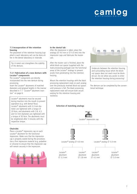
Selection of matching analogs<br />
Locator ® impression cap<br />
Undercuts between <strong>the</strong> retention housing<br />
and surrounding tissue which <strong>the</strong> blockout<br />
spacer does not reach must be blocked<br />
out. Do not allow any acrylic to enter<br />
<strong>the</strong> retention housing during processing!<br />
The denture can be completed by <strong>the</strong> conventional<br />
technique.<br />
Locator ® analog Ø 4.0 mm Locator ® analog Ø 5.0 mm<br />
Locator ®<br />
abutment<br />
Ø 3.3 mm<br />
Locator ®<br />
abutment<br />
Ø 3.8 mm<br />
Locator ®<br />
abutment<br />
Ø 4.3 mm<br />
Locator ®<br />
abutment<br />
Ø 5.0 mm<br />
7