DG-1000T - DG Flugzeugbau
DG-1000T - DG Flugzeugbau
DG-1000T - DG Flugzeugbau

You also want an ePaper? Increase the reach of your titles
YUMPU automatically turns print PDFs into web optimized ePapers that Google loves.
Flight manual <strong>DG</strong>-<strong>1000T</strong><br />
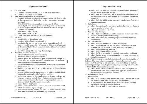
3. C.G. Tow hook:-<br />
a) check the ring muzzle of the C.G. hook for wear and function;<br />
b) check for cleanliness and corrosion;<br />
4. Main landing gear and nose wheel (if fitted):-<br />
a) check the struts, the gear box, the gear doors and the tyre for wear; dirt<br />
in the struts can hinder the landing gear from locking over centre the<br />
next time!;<br />
With TN1000/13 executed, standard from ser. no. 10-133 on:<br />
Check all parts of the landing gear positive locking device (notch and latch<br />
at the landing gear struts) for dirt. Check the Bowden cable for damage.<br />
b) check the tyre pressure;<br />
main wheel: 2.5 bar - 36 psi<br />
nose wheel: 2.5 bar - 36 psi<br />
c) check wheel brake and hose for wear and function;<br />
5. Left wing:-<br />
a) check locking of the outboard wing;<br />
b) check the aileron for excessive free play;<br />
c) check airbrake- and box and control rod for wear and free play. It<br />
must be possible to retract the airbrake, even if it is pressed backwards<br />
in direction of flight. If there is any water in the airbrake box this has<br />
to be removed;<br />
d) check the locking of the rear wing attachment pin.<br />
6. Powerplant and brake fluid level:-<br />
a) all screwed connections and their securing<br />
b) function of throttle, and propeller brake<br />
c) ignition system incl. wires and the spark plug connectors for tight fit<br />
d) Check drive belt for wear and correct tension, sudden loss of tension<br />
indicates damage of the engine assembly<br />
e) engine retaining cable and its connections in the engine compartment<br />
and at the engine<br />
f) fuel lines, electrical wires, bowden cables and structural parts for wear<br />
and kinks.<br />
g) exhaust muffler, propeller mount, cooling air guides, mechanical fuel<br />
pump and accessories for tight fit and any cracking.<br />
h) apply strong pressure to the propellermount in forward, backward and<br />
sideward directions to check if the bolted connection between the<br />
engine block and the propeller mount or any thing else is loose or<br />
damaged. Check the rubber engine mounts also.<br />
i) visual check of the propeller<br />
j) turn the propeller 1 revolution by hand and listen for abnormal sounds<br />
which may indicate engine damage<br />
l) drain condensed water from the fuel tank. The drainer is located in the<br />
main wheel box on the rear wall on the right hand side.<br />
Issued: February 2011 TM 1000/18 EASA app. 4.9<br />
Flight manual <strong>DG</strong>-<strong>1000T</strong><br />
m) check the outlet of the fuel tank ventline for cleanliness, the outlet is<br />
located behind the landing gear box.<br />
n) check if the propeller-stopper will be pressed forward by its gas-strut,<br />
the powerplant must be in the position propeller-stopper extended for<br />
this check.<br />
o) check the brake fluid level, the reservoir is installed in the front of the<br />
engine compartment;<br />
7. Tail wheel:-<br />
a) check for wear, free play and excessive dirt in the wheel box. Remove<br />
excessive dirt prior to take off;<br />
b) check tyre pressure: 4 bar -58 psi;<br />
8. Rear end of the fuselage:-<br />
a) check the lower rudder hinge and the connection of the rudder cables<br />
for wear, free play and correct securing;<br />
b) check the bulkhead and fin trailing edge shear web for cracks and<br />
delamination;<br />
9. Fin - horizontal tail:-<br />
a) check the upper rudder hinge for wear and free play;<br />
b) check the elevator for free play and correct control hook-up , look<br />
from the rear into the gap at the right hand side of the rudder;<br />
c) check the securing of the stabilizer;<br />
d) check the horizontal tail for free play;<br />
e) check the TE or Multiprobe for correct insertion and fix it with tape<br />
f) check the trim-weight box, correct number of weights, locking device<br />
completely engaged?<br />
Caution: When changing the trim ballast check condition and correct gluing of<br />
the foam rubber rings to the mounting plate of the optical sensors in the trimweight<br />
box. Without rings an indication error of the control lamp in the front<br />
instrument panel might occur. Replace missing rings according to Service Info<br />
67-07(attached to the maintenance manual).<br />
g) check if a fin battery is installed: If the ends of the locking bow are<br />
visible on both sides in the fairings at the upper end of the fin this is<br />
the indication that no battery is installed.<br />
10. Right wing see item 5.<br />
11. Fuselage nose<br />
a) check the ports for the static pressure and the pitot pressure and for the<br />
PC pressure (at the lower fuselage side) for cleanliness.<br />
b) if the motorglider was parked in rain, you have to empty the static<br />
ports by sucking out the water at the ports.<br />
c) check the nose hook for cleanliness and corrosion.<br />
Issued: February 2011 TM 1000/18 EASA app. 4.10