DG-1000T - DG Flugzeugbau
DG-1000T - DG Flugzeugbau
DG-1000T - DG Flugzeugbau

You also want an ePaper? Increase the reach of your titles
YUMPU automatically turns print PDFs into web optimized ePapers that Google loves.
Flight manual <strong>DG</strong>-<strong>1000T</strong><br />
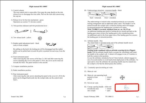
1) Control column<br />
The rear control stick is removable. First open the snap shackle at the trim<br />
release lever to disengage the trim cable. Pull out the stick after unscrewing<br />
the cap nut.<br />
2) Release lever for the trim mechanism - green<br />
Operation see section 7.5 elevator control<br />
3) Trim position indicator and trim preselection lever<br />
4) Tow release knob - yellow<br />
5) Rudder pedal adjustment knob – black<br />
(only in front cockpit)<br />
By pulling on the knob, the locking pin will be disengaged and the rudder<br />
pedals can be pulled back towards the pilot or pushed forward away from the<br />
pilot.<br />
6) Front instrument panel<br />
After removing the side screws at the base 2 x M 6 and after removing the<br />
screws attaching the cover to the panel 6 x M 4, the cover can be removed<br />
towards the front. The panel remains in the aircraft.<br />
7) Compass installation position<br />
8) Radio installation position<br />
9) Rear instrument panel<br />
After removing the side screws attaching the panel to the cover (4 x M 4) the<br />
panel can be hinged backwards into the cockpit (take out the control stick<br />
first!).<br />
Issued: July 2005 7.4<br />
Flight manual <strong>DG</strong>-<strong>1000T</strong><br />
10) Undercarriage retraction - extension handle - black<br />
back = retracted, front = extended,<br />
The undercarriage is locked in the extended position by an overcentre<br />
locking arrangement and an additional safety catch. The handle is to be<br />
turned towards the cockpit wall, so that the locking catch will engage.<br />
In retracted position the landing gear is locked over centre.<br />
With TN1000/13 executed, standard from ser. no. 10-133 on:<br />
An additional landing gear positive locking device (notch and latch at the<br />
landing gear struts) secures the landing gear in the extended position.<br />
An additional catch in the front upper area of the landing gear box secures<br />
the landing gear in retracted position.<br />
11) Airbrake handle - blue<br />
The wheel brake is operated at the end of the airbrake handle travel.<br />
Parking brake combined with an airbrake securing device (Piggotthook):<br />
Pull the airbrake handle back to actuate the wheelbrake and rotate<br />
the handle to the cockpit wall. A detent will engage in one of 4 notches to<br />
hold the system in this position.<br />
In case the airbrakes mistakenly haven’t been locked, a detent engages in<br />
one of several notches to avoid inadvertent deployment of the airbrakes. To<br />
open and to close the airbrakes the operating handle must be rotated into<br />
the cockpit so far that the detent passes the notches.<br />
12) Constantly open de-misting air vents<br />
13) Main air vent<br />
14) Main air vent operating knob<br />
pushed to front = closed<br />
pulled = open<br />
15) Swivel air vents<br />
16) Canopy opening handle - white-red<br />
towards the nose = closed<br />
into cockpit = open<br />
Issued: February 2008 TN 1000/13 7.5