

electronic telephone sets coaxial cable systems - The history of ...
electronic telephone sets coaxial cable systems - The history of ...
electronic telephone sets coaxial cable systems - The history of ...

You also want an ePaper? Increase the reach of your titles
YUMPU automatically turns print PDFs into web optimized ePapers that Google loves.
26<br />
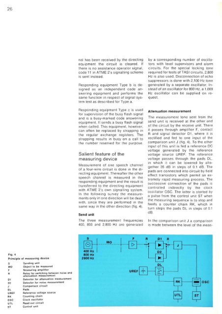
Fig. 4<br />
Principle <strong>of</strong> measuring device<br />
S Sending unit<br />
MO Object to be measured<br />
F Measuring amplifier<br />
R Relay for switching between noise and<br />
attenuation measurement<br />
D1 Detector for attenuation measurement<br />
D2 Detector for noise measurement<br />
J Comparison circuit<br />
DL Pads<br />
UREF Reference voltage source<br />
RK Counting chain<br />
OSC Clock oscillator<br />
UTL Read-out circuit<br />
ST Control unit<br />
nal has been received by the directing<br />
equipment the circuit is cleared. If<br />
there is no assistance operator signal,<br />
code 11 in ATME 2's signalling scheme<br />
is sent instead.<br />
Responding equipment Type b is designed<br />
as an independent code answering<br />
equipment and performs the<br />
same function in respect <strong>of</strong> signal system<br />
test as described for Type a.<br />
Responding equipment Type c is used<br />
for supervision <strong>of</strong> the busy flash signal<br />
and is a busy-marked code answering<br />
equipment. It sends a busy flash signal<br />
when called. This equipment, however,<br />
can <strong>of</strong>ten be replaced by strapping in<br />
the regular exchange registers. <strong>The</strong><br />
strapping results in busy on a call to<br />
the number reserved for the purpose.<br />
Salient feature <strong>of</strong> the<br />
measuring device<br />
Measurement <strong>of</strong> one speech channel<br />
<strong>of</strong> a four-wire circuit is done in the directing<br />
equipment. <strong>The</strong>reafter the other<br />
speech channel is measured in the<br />
responding equipment and the result is<br />
transferred to the directing equipment<br />
with ATME 2's own signalling system.<br />
In the following survey the measurements<br />
only in one direction will be dealt<br />
with, since they are performed in the<br />
same way in the other direction (fig. 4).<br />
Send unit<br />
<strong>The</strong> three measurement frequencies<br />
400, 800 and 2,800 Hz are generated<br />
by a corresponding number <strong>of</strong> oscillators<br />
with level supervisors and alarm<br />
circuits. For the special locking tone<br />
required for tests <strong>of</strong> TASI circuits, 2,800<br />
Hz is also used. Disconnection <strong>of</strong> echo<br />
suppressors is done with 2,100 Hz tone<br />
generated by a separate oscillator. Instead<br />
<strong>of</strong> an oscillator for 800 Hz, a 1,000<br />
Hz oscillator can be supplied on request.<br />
Attenuation measurement<br />
<strong>The</strong> measurement tone sent from the<br />
send unit is received at the other end<br />
<strong>of</strong> the circuit by the receive unit. <strong>The</strong>re<br />
it passes through amplifier F, contact<br />
R and signal detector D1, where it is<br />
rectified and fed to one input <strong>of</strong> the<br />
comparison unit J (fig. 4). To the other<br />
input <strong>of</strong> this unit is fed a reference DC<br />
voltage generated by the reference<br />
voltage source UREF. <strong>The</strong> reference<br />
voltage passes through the pads DL,<br />
in which it can be lowered by altogether<br />
35 dB in steps <strong>of</strong> 0.1 dB. <strong>The</strong><br />
pads are connected into circuit by field<br />
effect transistors which permit an extremely<br />
rapid measuring process. <strong>The</strong><br />
successive connection <strong>of</strong> the pads is<br />
controlled indirectly by the clock<br />
oscillator OSC. <strong>The</strong> latter is started by<br />
a pulse from the control unit ST when<br />
the measuring sequence is to stop and<br />
feeds a counter chain RK, which in<br />
turn steps the pads DL in steps <strong>of</strong> 0.1<br />
dB.<br />
In the comparison unit J a comparison<br />
is made between the level <strong>of</strong> the meas-


