

electronic telephone sets coaxial cable systems - The history of ...
electronic telephone sets coaxial cable systems - The history of ...
electronic telephone sets coaxial cable systems - The history of ...

Create successful ePaper yourself
Turn your PDF publications into a flip-book with our unique Google optimized e-Paper software.
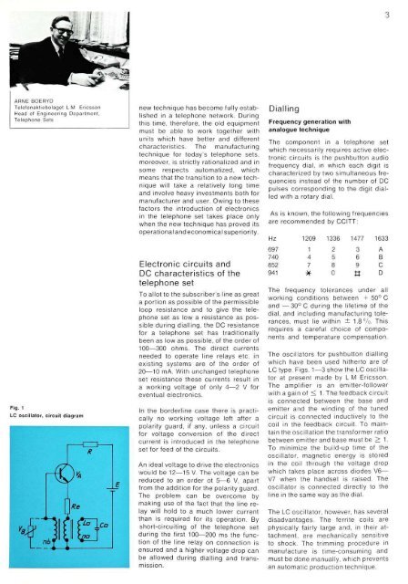
Fig. 1<br />
LC oscillator, circuit diagram<br />
new technique has become fully established<br />
in a <strong>telephone</strong> network. During<br />
this time, therefore, the old equipment<br />
must be able to work together with<br />
units which have better and different<br />
characteristics. <strong>The</strong> manufacturing<br />
technique for today's <strong>telephone</strong> <strong>sets</strong>,<br />
moreover, is strictly rationalized and in<br />
some respects automatized, which<br />
means that the transition to a new technique<br />
will take a relatively long time<br />
and involve heavy investments both for<br />
manufacturer and user. Owing to these<br />
factors the introduction <strong>of</strong> <strong>electronic</strong>s<br />
in the <strong>telephone</strong> set takes place only<br />
when the new technique has proved its<br />
operational and economical superiority.<br />
Electronic circuits and<br />
DC characteristics <strong>of</strong> the<br />
<strong>telephone</strong> set<br />
To allot to the subscriber's line as great<br />
a portion as possible <strong>of</strong> the permissible<br />
loop resistance and to give the <strong>telephone</strong><br />
set as low a resistance as possible<br />
during dialling, the DC resistance<br />
for a <strong>telephone</strong> set has traditionally<br />
been as low as possible, <strong>of</strong> the order <strong>of</strong><br />
100—300 ohms. <strong>The</strong> direct currents<br />
needed to operate line relays etc. in<br />
existing <strong>systems</strong> are <strong>of</strong> the order <strong>of</strong><br />
20—10 mA. With unchanged <strong>telephone</strong><br />
set resistance these currents result in<br />
a working voltage <strong>of</strong> only 4—2 V for<br />
eventual <strong>electronic</strong>s.<br />
In the borderline case there is practically<br />
no working voltage left after a<br />
polarity guard, if any, unless a circuit<br />
for voltage conversion <strong>of</strong> the direct<br />
current is introduced in the <strong>telephone</strong><br />
set for feed <strong>of</strong> the circuits.<br />
An ideal voltage to drive the <strong>electronic</strong>s<br />
would be 12—15 V. <strong>The</strong> voltage can be<br />
reduced to an order ot 5—6 V, apart<br />
from the addition for the polarity guard.<br />
<strong>The</strong> problem can be overcome by<br />
making use <strong>of</strong> the fact that the line relay<br />
will hold to a much lower current<br />
than is required for its operation. By<br />
short-circuiting <strong>of</strong> the <strong>telephone</strong> set<br />
during the first 100—200 ms the function<br />
<strong>of</strong> the line relay on connection is<br />
ensured and a higher voltage drop can<br />
be allowed during dialling and transmission.<br />
Dialling<br />
Frequency generation with<br />
analogue technique<br />
<strong>The</strong> component in a <strong>telephone</strong> set<br />
which necessarily requires active <strong>electronic</strong><br />
circuits is the pushbutton audio<br />
frequency dial, in which each digit is<br />
characterized by two simultaneous frequencies<br />
instead <strong>of</strong> the number <strong>of</strong> DC<br />
pulses corresponding to the digit dialled<br />
with a rotary dial.<br />
As is known, the following frequencies<br />
are recommended by CCITT:<br />
<strong>The</strong> frequency tolerances under all<br />
working conditions between + 50° C<br />
and — 30° C during the lifetime <strong>of</strong> the<br />
dial, and including manufacturing tolerances,<br />
must lie within ± 1.8%. This<br />
requires a careful choice <strong>of</strong> components<br />
and temperature compensation.<br />
<strong>The</strong> oscillators for pushbutton dialling<br />
which have been used hitherto are <strong>of</strong><br />
LC type. Figs. 1—3 show the LC oscillator<br />
at present made by L M Ericsson.<br />
<strong>The</strong> amplifier is an emitter-follower<br />
with a gain <strong>of</strong> < 1. <strong>The</strong> feedback circuit<br />
is connected between the base and<br />
emitter and the winding <strong>of</strong> the tuned<br />
circuit is connected inductively to the<br />
coil in the feedback circuit. To maintain<br />
the oscillation the transformer ratio<br />
between emitter and base must be > 1.<br />
To minimize the build-up time <strong>of</strong> the<br />
oscillator, magnetic energy is stored<br />
in the coil through the voltage drop<br />
which takes place across diodes V6—<br />
V7 when the handset is raised. <strong>The</strong><br />
oscillator is connected directly to the<br />
line in the same way as the dial.<br />
<strong>The</strong> LC oscillator, however, has several<br />
disadvantages. <strong>The</strong> ferrite coils are<br />
physically fairly large and, in their attachment,<br />
are mechanically sensitive<br />
to shock. <strong>The</strong> trimming procedure in<br />
manufacture is time-consuming and<br />
must be done manually, which prevents<br />
an automatic production technique.<br />
3


