

electronic telephone sets coaxial cable systems - The history of ...
electronic telephone sets coaxial cable systems - The history of ...
electronic telephone sets coaxial cable systems - The history of ...

Create successful ePaper yourself
Turn your PDF publications into a flip-book with our unique Google optimized e-Paper software.
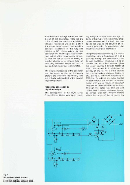
Fig. 4<br />
RC oscillator, circuit diagram<br />
Fi oscillator amplifier, frequency group 1<br />
Fi oscillator amplifier, frequency group 2<br />
acts the rise <strong>of</strong> voltage across the feed<br />
circuit <strong>of</strong> the oscillator. From the DC<br />
point <strong>of</strong> view the oscillator exhibits a<br />
variable resistance which on a short<br />
line draws more current than would a<br />
constant resistance. In this way one<br />
obtains a DC characteristic for the<br />
oscillator unit which is practically identical<br />
to that <strong>of</strong> the transmission circuit,<br />
so that the risk <strong>of</strong> transients owing to<br />
sudden change <strong>of</strong> a voltage drop on<br />
switching between <strong>telephone</strong> set circuit<br />
and dialling circuit is eliminated.<br />
<strong>The</strong> output impedance <strong>of</strong> the oscillator<br />
and the levels for the two frequency<br />
groups are selected individually and<br />
are entirely independent <strong>of</strong> the current<br />
regulating circuit.<br />
Frequency generation by<br />
digital technique<br />
<strong>The</strong> development <strong>of</strong> the MOS (Metal<br />
Oxide Silicon Gate) technique, result<br />
5<br />
ing in digital counters and storage circuits<br />
<strong>of</strong> LSI type with extremely small<br />
power requirement for their function,<br />
opens the way to the solution <strong>of</strong> frequency<br />
generation for pushbutton dialling<br />
by using digital technique.<br />
<strong>The</strong> principle is shown in fig. 5. A crystal<br />
oscillator, with a frequency <strong>of</strong> 1 MHz<br />
passing through the two binary counters<br />
AD and BD, <strong>of</strong> which AD is a 10-bit<br />
counter and BD a 9-bit counter, gives<br />
the larger counter a division factor up<br />
1024. This results in a minimum frequency<br />
<strong>of</strong> 976 Hz. For a 9-bit counter<br />
the corresponding division factor is<br />
512, giving a minimum frequency <strong>of</strong><br />
1953 Hz. By adding an extra flip-flop<br />
in each output one obtains a division<br />
factor <strong>of</strong> 2, which results in minimum<br />
frequencies <strong>of</strong> 488 and 976 respectively.<br />
Through the gates GA and GB and<br />
pushbutton contacts each counter can<br />
be zeroed after four division factors<br />
within the range <strong>of</strong> the bit speed for


