- Page 4 and 5: Organization This first national wo
- Page 6 and 7: Contents Organization…………
- Page 8 and 9: Program April 6, 2006 8:30-9:00 Rec
- Page 10 and 11: First National Workshop on Control
- Page 12 and 13: First National Workshop on Control
- Page 14 and 15: 1 User requirements defined 2 Syste
- Page 16 and 17: First National Workshop on Control
- Page 18 and 19: First National Workshop on Control
- Page 20 and 21: First National Workshop on Control
- Page 22 and 23: First National Workshop on Control
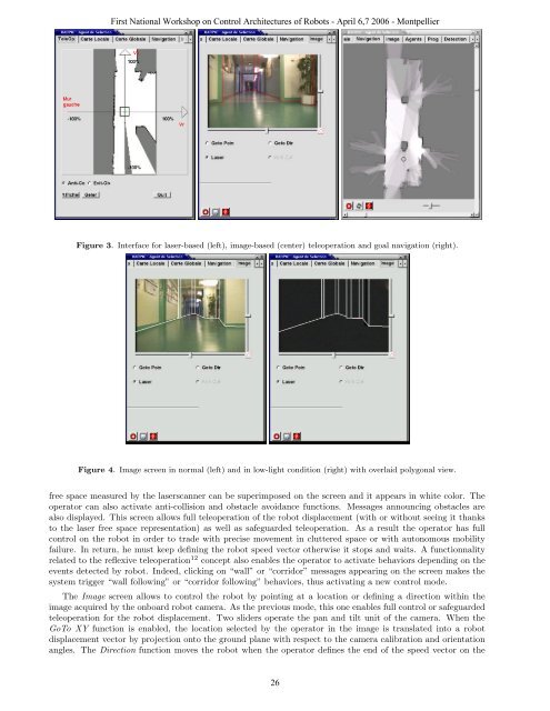
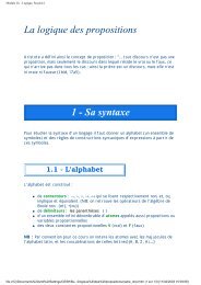
- Page 24 and 25: First National Workshop on Control
- Page 28 and 29: Figure 6. Interface for local map (
- Page 30 and 31: Figure 8. Map and robot trajectory
- Page 32 and 33: First National Workshop on Control
- Page 34 and 35: First National Workshop on Control
- Page 36 and 37: First National Workshop on Control
- Page 38 and 39: Decision Planning Navigation Guidan
- Page 40 and 41: First National Workshop on Control
- Page 42 and 43: • Three Petri nets model level 3:
- Page 44 and 45: First National Workshop on Control
- Page 46 and 47: First National Workshop on Control
- Page 48 and 49: Abstract First National Workshop on
- Page 50 and 51: eginning of the next one. A guidanc
- Page 52 and 53: Figure 5 - Supervision interface Fi
- Page 54 and 55: On-going tests First National Works
- Page 56 and 57: First National Workshop on Control
- Page 58 and 59: First National Workshop on Control
- Page 60 and 61: First National Workshop on Control
- Page 62 and 63: First National Workshop on Control
- Page 64 and 65: First National Workshop on Control
- Page 66 and 67: First National Workshop on Control
- Page 68 and 69: First National Workshop on Control
- Page 70 and 71: First National Workshop on Control
- Page 72 and 73: First National Workshop on Control
- Page 74 and 75: First National Workshop on Control
- Page 76 and 77:
DES (Data Exchange System), a publi
- Page 78 and 79:
First National Workshop on Control
- Page 80 and 81:
First National Workshop on Control
- Page 82 and 83:
First National Workshop on Control
- Page 84 and 85:
First National Workshop on Control
- Page 86 and 87:
First National Workshop on Control
- Page 88 and 89:
First National Workshop on Control
- Page 90 and 91:
First National Workshop on Control
- Page 92 and 93:
First National Workshop on Control
- Page 94 and 95:
Pilote Expérimenté:Télépilote F
- Page 96 and 97:
First National Workshop on Control
- Page 98 and 99:
First National Workshop on Control
- Page 100 and 101:
A multi-level architecture controll
- Page 102 and 103:
First National Workshop on Control
- Page 104 and 105:
First National Workshop on Control
- Page 106 and 107:
The autonomous parts Basic levels F
- Page 108 and 109:
First National Workshop on Control
- Page 110 and 111:
cluster of the perception part of t
- Page 112 and 113:
First National Workshop on Control
- Page 114 and 115:
First National Workshop on Control
- Page 116 and 117:
First National Workshop on Control
- Page 118 and 119:
An ultrasound probe of a sonographe
- Page 120 and 121:
Abstract First National Workshop on
- Page 122 and 123:
First National Workshop on Control
- Page 124 and 125:
First National Workshop on Control
- Page 126 and 127:
nombre de branches dans le parallé
- Page 128 and 129:
First National Workshop on Control
- Page 130 and 131:
First National Workshop on Control
- Page 132 and 133:
2 The Orccad architecture 2.1 Basic
- Page 134 and 135:
First National Workshop on Control
- Page 136 and 137:
First National Workshop on Control
- Page 138 and 139:
First National Workshop on Control
- Page 140 and 141:
5.3 Real-time structures At compile
- Page 142 and 143:
From a software engineering perspec
- Page 144 and 145:
First National Workshop on Control
- Page 146 and 147:
First National Workshop on Control
- Page 148 and 149:
First National Workshop on Control
- Page 150 and 151:
First National Workshop on Control
- Page 152 and 153:
First National Workshop on Control
- Page 154 and 155:
First National Workshop on Control
- Page 156 and 157:
First National Workshop on Control
- Page 158 and 159:
First National Workshop on Control
- Page 160 and 161:
First National Workshop on Control
- Page 162 and 163:
First National Workshop on Control
- Page 164 and 165:
First National Workshop on Control
- Page 166 and 167:
First National Workshop on Control
- Page 168 and 169:
First National Workshop on Control
- Page 170 and 171:
First National Workshop on Control
- Page 172 and 173:
First National Workshop on Control
- Page 174 and 175:
First National Workshop on Control
- Page 176 and 177:
First National Workshop on Control
- Page 178 and 179:
First National Workshop on Control
- Page 180 and 181:
First National Workshop on Control
- Page 182 and 183:
First National Workshop on Control
- Page 184 and 185:
First National Workshop on Control
- Page 186 and 187:
Stopped destination reached destina
- Page 188 and 189:
� ��� � �����
- Page 190 and 191:
First National Workshop on Control
- Page 192 and 193:
Abstract Horocol language and Hardw
- Page 194 and 195:
First National Workshop on Control
- Page 196 and 197:
• langage.xml which describe the
- Page 198 and 199:
Coordination programming in Horocol
- Page 200 and 201:
[F8] resume [F9] restart [F10] reev
- Page 202 and 203:
References First National Workshop
- Page 204 and 205:
First National Workshop on Control
- Page 206 and 207:
TABLE I PROBABILITY VALUES FOR PERC
- Page 208 and 209:
First National Workshop on Control