Pleading for open modular architectures - Lirmm
Pleading for open modular architectures - Lirmm
Pleading for open modular architectures - Lirmm

Create successful ePaper yourself
Turn your PDF publications into a flip-book with our unique Google optimized e-Paper software.
First National Workshop on Control Architectures of Robots - April 6,7 2006 - Montpellier<br />
The decisional architecture is based on the<br />
ProCoSA program [3], which was developed<br />
<strong>for</strong> programming and execution monitoring of<br />
autonomous systems. Behavior of the vehicle<br />
during the mission is described by Petri nets<br />
[4] (directed graphs with two kinds of nodes,<br />
called places and transitions); in ProCoSA,<br />
places represent the considered behavior<br />
internal states and transitions indicate the<br />
phenomenon that change the behavior<br />
execution state. The Petri Player of ProCoSA<br />
is the complex automate which runs the<br />
system in accordance with Petri nets and<br />
computation software such as the planning<br />
and guidance programs.<br />
Man-Machine Interface<br />
The Man Machine Interface, named IOVAS,<br />
provides several graphical tools to prepare,<br />
check and supervise missions of different<br />
kinds of vehicles: AUVs, ships.<br />
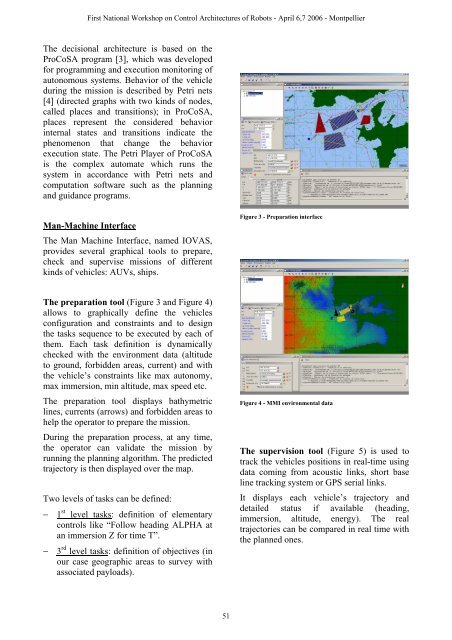
The preparation tool (Figure 3 and Figure 4)<br />
allows to graphically define the vehicles<br />
configuration and constraints and to design<br />
the tasks sequence to be executed by each of<br />
them. Each task definition is dynamically<br />
checked with the environment data (altitude<br />
to ground, <strong>for</strong>bidden areas, current) and with<br />
the vehicle’s constraints like max autonomy,<br />
max immersion, min altitude, max speed etc.<br />
The preparation tool displays bathymetric<br />
lines, currents (arrows) and <strong>for</strong>bidden areas to<br />
help the operator to prepare the mission.<br />
During the preparation process, at any time,<br />
the operator can validate the mission by<br />
running the planning algorithm. The predicted<br />
trajectory is then displayed over the map.<br />
Two levels of tasks can be defined:<br />
− 1 st level tasks: definition of elementary<br />
controls like “Follow heading ALPHA at<br />
an immersion Z <strong>for</strong> time T”.<br />
− 3 rd level tasks: definition of objectives (in<br />
our case geographic areas to survey with<br />
associated payloads).<br />
51<br />
Figure 3 - Preparation interface<br />
Figure 4 - MMI environmental data<br />
The supervision tool (Figure 5) is used to<br />
track the vehicles positions in real-time using<br />
data coming from acoustic links, short base<br />
line tracking system or GPS serial links.<br />
It displays each vehicle’s trajectory and<br />
detailed status if available (heading,<br />
immersion, altitude, energy). The real<br />
trajectories can be compared in real time with<br />
the planned ones.