

Switch Mode Battery Eliminator Based on a PIC16C72A - Microchip
Switch Mode Battery Eliminator Based on a PIC16C72A - Microchip
Switch Mode Battery Eliminator Based on a PIC16C72A - Microchip

Create successful ePaper yourself
Turn your PDF publications into a flip-book with our unique Google optimized e-Paper software.
AN701<br />
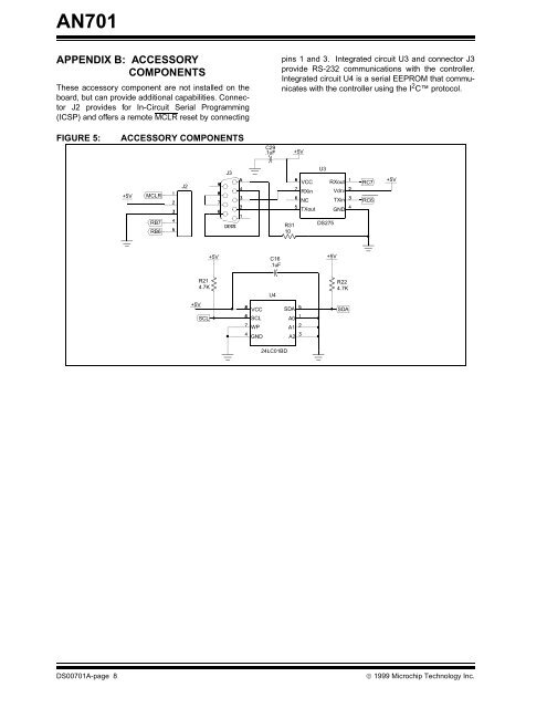
APPENDIX B: ACCESSORY<br />
COMPONENTS<br />
These accessory comp<strong>on</strong>ent are not installed <strong>on</strong> the<br />
board, but can provide additi<strong>on</strong>al capabilities. C<strong>on</strong>nector<br />
J2 provides for In-Circuit Serial Programming<br />
(ICSP) and offers a remote MCLR reset by c<strong>on</strong>necting<br />
FIGURE 5: ACCESSORY COMPONENTS<br />
+5V<br />
MCLR<br />
RB7<br />
RB6<br />
J2<br />
+5V<br />
R21<br />
4.7K<br />
SCL<br />
+5V<br />
J3<br />
VCC<br />
SCL<br />
WP<br />
GND<br />
C29<br />
.1uF<br />
pins 1 and 3. Integrated circuit U3 and c<strong>on</strong>nector J3<br />
provide RS-232 communicati<strong>on</strong>s with the c<strong>on</strong>troller.<br />
Integrated circuit U4 is a serial EEPROM that communicates<br />
with the c<strong>on</strong>troller using the I 2 C protocol.<br />
DS00701A-page 8 © 1999 <strong>Microchip</strong> Technology Inc.<br />
C16<br />
.1uF<br />
U4<br />
24LC01BD<br />
R31<br />
10<br />
SDA<br />
A0<br />
A1<br />
A2<br />
+5V<br />
VCC<br />
RXin<br />
NC<br />
TXout<br />
U3<br />
DS275<br />
RXout<br />
Vdrv<br />
TXin<br />
GND<br />
+5V<br />
R22<br />
4.7K<br />
SDA<br />
RC7<br />
RC6<br />
+5V


