BRS-6 General Installation Guide - CAFE Foundation
BRS-6 General Installation Guide - CAFE Foundation
BRS-6 General Installation Guide - CAFE Foundation

Create successful ePaper yourself
Turn your PDF publications into a flip-book with our unique Google optimized e-Paper software.
Once ignited, the grains will burn on all exposed surfaces to form hot gases that are exhausted<br />
through the nozzle. The propellant's performance is a function of its burning rate and the<br />
burning surface area of the grain. The geometry of the grain is therefore critical to achieving<br />
the desired thrust profile. Our rocket motors use grains with a cylindrical bores through their<br />
centers, or internal burning grains, to achieve the desired burn surface area.<br />
The rocket motor nozzle provides for the expansion and supersonic acceleration of the hot<br />
gases. The rocket motor's performance is a function of the propellant performance and the<br />
nozzle design and can be defined by its thrust versus time curve and the total impulse, It ,<br />
which is the thrust force, F (which can vary with time) integrated over the burning time, t.<br />
Each <strong>BRS</strong> rocket motor has been designed with a thrust-time curve and total impulse that<br />
specifically meet the extraction requirements of the particular parachute.<br />
Solid fuel motors have a flame, but this is not the problem some imagine for two reasons; one<br />
simple, one more complex. With an extremely high departure velocity in the first tenth of a<br />
second, the flame is gone before it can cause problems. The more complex explanation<br />
involves a pressure front set up by the ignited fuel. The main content of the rocket’s exhaust is<br />
water vapor and non-flammable gases. These expand so rapidly that they will literally push<br />
away fuel fumes before they can get warm enough to ignite.<br />
<strong>BRS</strong> currently certifies its solid-fuel rockets for twelve (12) years of service life. At the time of<br />
expiration, the old rocket must be properly disposed of and replaced with a new one. However,<br />
this means that a rocket shipped from <strong>BRS</strong> to a customer need never be returned to the factory<br />
for service, eliminating any owner difficulty in shipping hazardous goods.<br />
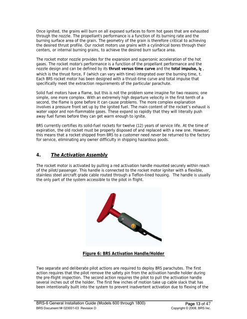
4. The Activation Assembly<br />
The rocket motor is activated by pulling a red activation handle mounted securely within reach<br />
of the pilot/passenger. This handle is connected to the rocket motor igniter with a flexible,<br />
stainless steel aircraft grade cable routed through a Teflon-lined housing. The handle is usually<br />
the only part of the system accessible to the pilot in flight.<br />
Figure 6: <strong>BRS</strong> Activation Handle/Holder<br />
Two separate and deliberate pilot actions are required to deploy <strong>BRS</strong> parachutes. The first<br />
action requires that the pilot remove the safety pin from the activation handle holder during<br />
the pre-flight inspection. The second action requires the pilot to pull the activation handle<br />
several inches out of the holder. The first few inches of motion take up cable slack that has<br />
been intentionally built into the system to prevent inadvertent activation due to flexing of the<br />
<strong>BRS</strong>-6 <strong>General</strong> <strong>Installation</strong> <strong>Guide</strong> (Models 600 through 1800) Page 13 of 47<br />
<strong>BRS</strong> Document № 020001-03 Revision D Copyright © 2008, <strong>BRS</strong> Inc.