Practical Soil Nail Wall Design and Constructability Issues
Practical Soil Nail Wall Design and Constructability Issues
Practical Soil Nail Wall Design and Constructability Issues

Create successful ePaper yourself
Turn your PDF publications into a flip-book with our unique Google optimized e-Paper software.
<strong>Practical</strong> <strong>Soil</strong> <strong>Nail</strong> <strong>Wall</strong> <strong>Design</strong><br />
<strong>and</strong> <strong>Constructability</strong> <strong>Issues</strong><br />
by<br />
Walter G. Kutschke, P.E.<br />
URS Corporation, Pittsburgh, Pennsylvania<br />
Fred S. Tarquinio, P.E.<br />
Nicholson Construction Company, Cuddy, Pennsylvania<br />
William K. Petersen, P.E.<br />
URS Corporation, Fort Washington, Pennsylvania<br />
Presented at:<br />
The Broadmoor<br />
DFI’s 32nd Annual Conference on Deep Foundations<br />
Colorado Springs, Colorado<br />
October 11-13, 2007<br />
Nicholson Construction Company<br />
12 McClane Street<br />
Cuddy, PA 15031<br />
Telephone: 412-221-4500<br />
Facsimile: 412-221-3127<br />
07-02-157
PRACTICAL SOIL NAIL WALL DESIGN AND CONSTRUCTABILITY ISSUES<br />
Walter G. Kutschke, P.E., URS Corporation, Pittsburgh, Pennsylvania, USA<br />
Fred S. Tarquinio, P.E., Nicholson Construction Company, Cuddy, Pennsylvania, USA<br />
William K. Petersen, P.E., URS Corporation, Ft. Washington, Pennsylvania, USA<br />
Introduction<br />
Four significant soil nail wall projects in the eastern United States were recently<br />
completed with a combined area of 175,000 square feet of finished shotcrete surface.<br />
These projects required the use of innovative design <strong>and</strong> construction methods in order<br />
to address various challenges, including slide-prone back slope materials, perched water,<br />
highly erodible rock materials, curved wall alignments, very tight construction tolerances<br />
<strong>and</strong> unexpected subsurface conditions. Special focus is given to issues such as bench<br />
excavation, soil nail installation methods, shotcrete mix design, anticipated shotcrete<br />
quantities, shotcrete nozzlemen qualifications <strong>and</strong> weather conditions, in order to provide<br />
a lessons-learned database for future soil nail wall design <strong>and</strong> inspector considerations.<br />
These projects also underscore the importance of design engineer <strong>and</strong> soil nail wall<br />
contractor qualifications as well as effective communication with the owner.<br />
The intent of this paper is not to reiterate the<br />
design <strong>and</strong> inspector guidelines presented in<br />
FHWA (2003) <strong>and</strong> FHWA (1994), but rather to<br />
present issues that occurred during the<br />
construction of four significant soil nail wall<br />
projects in the eastern United States. Although<br />
each project is different with regard to geologic<br />
conditions <strong>and</strong> design, these projects each<br />
experienced some similar situations. These<br />
similarities indicate a trend in design,<br />
specification <strong>and</strong> construction of soil nail wall<br />
projects. It is in these situations that lessons are<br />
learned <strong>and</strong> presented herein.<br />
The first soil nail wall project referenced herein<br />
was part of a larger project involving the<br />
construction of a new railroad alignment in the<br />
relatively mountainous terrain of western<br />
Pennsylvania. This project involved the<br />
construction of over 9,000 square feet of soil nail<br />
retaining structure with a total of 13,800 lineal<br />
feet of soil nails <strong>and</strong> 428 cubic yards of<br />
shotcrete. In addition, the project also required<br />
construction of a shotcrete slope protection<br />
system which used very similar construction<br />
techniques as those employed for soil nail walls.<br />
This effort required the placement of<br />
approximately 90,000 square feet of slope<br />
protection with a total of 34,000 lineal feet of<br />
rock anchors <strong>and</strong> nearly 2,800 cubic yards of<br />
shotcrete. This system is believed to be the<br />
largest known application of such a system to<br />
date. Refer to Kutschke et al. (2007) for further<br />
details regarding this work.<br />
The second project involved the construction of<br />
a soil nail retaining wall used for the support of<br />
excavation for the new Chinese Embassy<br />
building in Washington, D.C. This project<br />
consisted of the installation of over 50,000<br />
square feet of exposed shotcrete wall surface,<br />
approximately 1,600 soil nails <strong>and</strong> over 1,600<br />
cubic yards of shotcrete.<br />
The third project involved the construction of a<br />
soil nail retaining wall for the support of<br />
excavation for a new retail development in<br />
eastern Pennsylvania. This project involved<br />
10,000 square feet of exposed shotcrete surface<br />
requiring 400 soil nails <strong>and</strong> 400 cubic yards of<br />
shotcrete.<br />
The last project also involved the construction of<br />
a shotcrete wall used for support of excavation<br />
for a new retail development in southwestern<br />
Pennsylvania. This project consisted of 16,000<br />
square feet of soil nail wall with approximately<br />
600 soil nails <strong>and</strong> 800 cubic yards of shotcrete.<br />
These projects were all successfully completed<br />
<strong>and</strong> are in service.<br />
Subsurface Conditions<br />
<strong>Soil</strong> nail wall construction is not appropriate for<br />
all soil conditions (FHWA, 2003). In the authors’<br />
opinion, well-drained cohesive soils, such as the
esidual clays <strong>and</strong> weathered bedrock<br />
characteristic of the Piedmont <strong>and</strong> Appalachian<br />
regions, are ideal for soil nail wall construction.<br />
The importance of soil type cannot be<br />
overemphasized, as illustrated by the following<br />
examples.<br />
The ground condition had been severely altered<br />
at one of the referenced projects just prior to its<br />
construction. Following completion of the field<br />
survey obtained for design activities, the original<br />
property owner had excavated a haul road into<br />
the hillside for log truck operations, with the road<br />
alignment corresponding roughly with the<br />
planned alignment of the soil nail wall. In order<br />
to re-establish the original ground surface to<br />
preclude backslope failures, the general<br />
contractor backfilled this haul road cut with<br />
poorly-compacted material having significant<br />
fines content. As excavation for the soil nail wall<br />
proceeded through this loose fill, which reached<br />
a maximum depth of about 6 feet at the wall<br />
face, a large degree of sloughing occurred,<br />
particularly in response to disturbance from<br />
drilling the nail holes. This condition was further<br />
exacerbated by a heavy rainfall event from the<br />
remnants of Hurricane Katrina. The changed<br />
ground elevations <strong>and</strong> slope failures created<br />
numerous problems related to the as-designed<br />
wall geometry, <strong>and</strong> additional survey <strong>and</strong> design<br />
effort was required to adapt the wall to fit these<br />
changed conditions. Furthermore, a very large<br />
volume of additional shotcrete was required to<br />
fill in voids where sloughing had taken place at<br />
the wall face. Since the backfilling operation<br />
occurred before the soil nail wall contractor had<br />
mobilized to the site, there was nobody present<br />
on-site that was able to foresee the dire<br />
consequences of this decision. A detailed preconstruction<br />
meeting, involving the general<br />
contractor, subcontractor <strong>and</strong> the engineer may<br />
have prevented this occurrence.<br />
Groundwater, surface runoff or perched water in<br />
the wall excavation are likely to cause stability<br />
<strong>and</strong> drainage problems during construction. In<br />
addition, the shotcrete may have a problem<br />
adhering to the excavated face if surface water<br />
is present. This was a major problem in a small<br />
area of the wall in eastern Pennsylvania. As a<br />
result, large quantities of shotcrete were<br />
required in order to maintain the alignment of<br />
this permanent wall.<br />
Excessive seepage can be detrimental to newly<br />
placed shotcrete because it acts to wash the<br />
cement off of the aggregate <strong>and</strong> to create<br />
additional load resulting in minor cracking <strong>and</strong><br />
sloughing to complete loss of shotcrete<br />
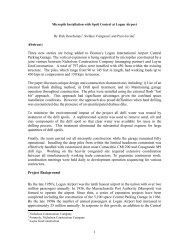
adhesion to the wall face. The most effective<br />
means to address seepage at the wall face is to<br />
control <strong>and</strong> direct the groundwater flow. The<br />
placement of additional drainage geocomposite<br />
<strong>and</strong> / or the use of PVC drain pipe to capture<br />
<strong>and</strong> direct the drainage away from the newly<br />
placed shotcrete have both been effective, as<br />
displayed by Figure 1, where drainage in excess<br />
of 80 gallons per hour was occurring at select<br />
Figure 1 – Additional <strong>Wall</strong> Drainage for Seepage<br />
Control<br />
locations along the shotcrete face. Although this<br />
is an extreme event, it demonstrates the<br />
effectiveness of this approach. The<br />
geocomposite drains <strong>and</strong> PVC drain pipe<br />
effectively collected <strong>and</strong> diverted the flow away<br />
from the slope face <strong>and</strong> allowed the placement<br />
of shotcrete in this instance. It is important to<br />
note that when these drainage measures are<br />
employed, they are self-supported by securing<br />
them to the slope face or steel reinforcement<br />
rather than relying on the shotcrete for support.<br />
Bench Excavation<br />
15± gals per hr<br />
80± gals per hr<br />
Bench excavation heights are not only limited to<br />
the st<strong>and</strong>-up time of the ground, but<br />
consideration must also be given to the<br />
nozzleman’s abilities. In order for the proper<br />
application of shotcrete, the nozzle must be<br />
perpendicular to the slope face. As the angle<br />
between the slope face <strong>and</strong> nozzle increases,<br />
the degree of compaction decreases with a<br />
corresponding increase in rebound. Bench<br />
heights beyond about 5 to 6 feet place additional<br />
burden on the nozzleman <strong>and</strong> can result in<br />
quality problems as the upper reaches are
difficult to shoot <strong>and</strong> finish properly. As such, it is<br />
the author’s experience that limiting the bench<br />
height to 5 to 6 feet enables a nozzleman to<br />
properly <strong>and</strong> safely shoot the wall face <strong>and</strong><br />
upper overlap area. Figure 2 displays a typical<br />
Figure 2 – Challenging Application of Shotcrete<br />
due to Excessive Bench Height Excavation<br />
situation when the bench height approaches this<br />
upper limit. The congested reinforcement zone<br />
in the overlap area requires particular attention<br />
that is difficult <strong>and</strong> burdensome for this<br />
experienced nozzleman. Also the ability for him<br />
to blend in the final shotcrete layer is further<br />
exacerbated as the rebound will significantly<br />
increase at the upper reaches (note the<br />
significant rebound that has all ready<br />
accumulated at the base). <strong>Design</strong> must utilize<br />
appropriate vertical distances between lifts<br />
considering not only soil conditions, but also<br />
practical heights between lifts as well as address<br />
maximum permissible bench lifts in the<br />
specifications. For comparison purposes, Figure<br />
3 indicates an appropriate bench excavation that<br />
will be much easier for a nozzleman to work<br />
with.<br />
Figure 3 – Appropriate Bench Height Excavation<br />
<strong>Nail</strong> Installation<br />
Air-track drilling is an economical drill method<br />
when drilling into materials that do not require<br />
casing to support the hole. Figure 4 illustrates a<br />
typical air-track drilling operation.<br />
Figure 4 – Typical Air-Track Drilling<br />
<strong>Soil</strong> nail drilling production rates are highly<br />
dependent on equipment <strong>and</strong> driller, but rates of<br />
1 to 2 feet per minute are typical values in hard<br />
clay or weathered rock. <strong>Nail</strong> hole diameters are<br />
generally limited to 4 to 5 inches with air-track<br />
equipment. Although these hole diameters<br />
theoretically provide sufficient grout coverage<br />
between the nail <strong>and</strong> bonding strata, the ability<br />
of the driller to consistently create a straight<br />
shaft is debatable. This consideration,<br />
combined with the natural sag of the bar as it<br />
deflects under self-weight between the<br />
centralizer support points, will significantly<br />
reduce grout coverage locally along the bar.<br />
Therefore, a centralizer spacing of less than the<br />
10-foot industry st<strong>and</strong>ard is warranted in<br />
environments that require long-term corrosion<br />
protection. Furthermore, centralizers should be<br />
secured to the soil nails by tie-wire; methods<br />
such a taping do not properly secure the<br />
centralizer <strong>and</strong> can result in bunching of the<br />
centralizers as the nails are inserted into the<br />
hole.<br />
Although air-track drills are an economical<br />
means of advancing a soil nail drill hole, the<br />
drilling operation can create significant<br />
disturbance at the slope face resulting in<br />
sloughing <strong>and</strong> soil break-outs. If this condition<br />
persists, a drill berm is highly effective, as<br />
shown on Figure 5.
Figure 5 – Prudent Application of a Drill Berm<br />
Figure 5 displays the slope face, in this case<br />
consisting of cohesive residual soil, after drilling<br />
<strong>and</strong> grouting. The dashed line noted in the figure<br />
represents the back-of-wall face. The use of a<br />
drill berm in this situation prevented the<br />
sloughing <strong>and</strong> general drill disturbance from<br />
impacting the back-of-wall face. There would<br />
have been substantial detrimental impacts to<br />
this structure had a drill berm not be used.<br />
Teleh<strong>and</strong>lers or similar machines are commonly<br />
used to lift a bundle of soil nails for the labor<br />
force to insert them into the grouted drill hole.<br />
Although this practice is acceptable, care should<br />
be taken as the nails are lifted from the forks. At<br />
no time should the inspector allow the nails to<br />
slide against the fork <strong>and</strong> into the hole. This<br />
needlessly exposes the nail to abrasion that can<br />
create holes in the epoxy coating. <strong>Nail</strong>s should<br />
be manually lifted <strong>and</strong> inserted into the hole.<br />
Structural Materials<br />
The most important aspects of material design<br />
<strong>and</strong> quality control with respect to soil nail walls<br />
are the nail grout <strong>and</strong> shotcrete. Typical nail<br />
grout consists of a cement <strong>and</strong> water<br />
combination with approximately 0.45<br />
water:cement ratio, having 28-day compressive<br />
strength of at least 4,000 psi. However, it is<br />
crucial in the timing of most soil nail projects to<br />
have 3-, 2- or possibly 1-day strength results.<br />
Shotcrete is generally applied using the wet-mix<br />
process (FHWA 2003). This process generally<br />
results in a higher volume throughput with less<br />
rebound. Wet-mix application rates for these<br />
projects were typically about 6 to 7 minutes per<br />
cubic yard of shotcrete. Similar to the nail grout,<br />
it is critical to have shotcrete compressive<br />
strength results at 3, 2 or 1 day(s) in order to<br />
maximize production without comprising the<br />
integrity of the wall.<br />
Proper mix design <strong>and</strong> adequate drainage are<br />
paramount to the longevity of the shotcrete face<br />
due to freeze / thaw cycling. Shotcrete slump is<br />
largely self-controlling; too wet <strong>and</strong> it will slough,<br />
too dry <strong>and</strong> it will not pump. A combination of<br />
proper air entrainment <strong>and</strong> a low water:cement<br />
ratio help provide adequate freeze / thaw<br />
durability. Published literature indicates that loss<br />
of entrained air during the pumping <strong>and</strong> spray<br />
application is typically 4-5% (FHWA 1998).<br />
Typical wet mix shotcrete designs require a<br />
water:cement ratio no greater than 0.45 with<br />
minimum air entrainment of 7 - 10%, measured<br />
at the truck. Pozzolans, such as fly ash,<br />
improve pumpability <strong>and</strong> will produce a more<br />
durable shotcrete by mitigating the alkali-silica<br />
reactions, increasing resistance to sulfate attack,<br />
<strong>and</strong> reducing ingress of potentially deleterious<br />
materials such as chloride <strong>and</strong> water. However,<br />
fly ash has the potential to impact air<br />
entrainment. Hill (2006) indicates that as the<br />
loss on ignition value of fly ash increases, the<br />
dosage of air entrainment chemical will generally<br />
increase. Suitable material selection is essential.<br />
Proper aggregate distribution is very important<br />
with regard to strength <strong>and</strong> durability of the<br />
finished shotcrete face, but also is very critical<br />
with regard to pumpability <strong>and</strong> the ability of the<br />
shotcrete mix to adhere to the excavated face.<br />
Figure 6 represents the recommended range of<br />
aggregate size distribution for a good shotcrete<br />
mix, which is in general conformance with<br />
FHWA (2003).<br />
Percent Passing by Weight<br />
100<br />
80<br />
60<br />
40<br />
20<br />
0<br />
100<br />
10<br />
1<br />
Sieve Size (mm)<br />
Figure 6 – Recommended Shotcrete Aggregate<br />
Proportions<br />
0.1
Shotcrete reinforcement is based on the<br />
structural requirements of the soil nail wall. In<br />
addition to this reinforcement, an additional layer<br />
of wire mesh-type reinforcement can be added.<br />
The wire mesh opening should be no smaller<br />
than 4 inches, since smaller openings will<br />
generally act to interfere with shotcrete<br />
placement. It is suggested that this mesh<br />
provides additional confinement to minimize<br />
shotcrete sag as a greater thickness of shotcrete<br />
is placed; however, its benefit is questionable<br />
<strong>and</strong> lift thickness should be limited to 6± inches<br />
even where it is used.<br />
<strong>Wall</strong> drainage is paramount to the longevity of a<br />
soil nail wall system. Geocomposite drainage<br />
panels or strips are often used to provide<br />
drainage. These materials are generally tacked<br />
to the slope face with a reinforcing pin <strong>and</strong><br />
installed in shingle fashion as the excavation is<br />
lowered. Drains are daylighted by means of a<br />
weephole, <strong>and</strong> care must be taken to avoid<br />
creating a low spot for water to collect. Weep<br />
holes must be covered during application of<br />
shotcrete to avoid clogging the drain. Extreme<br />
care must be taken by the nozzleman to avoid<br />
placing shotcrete behind the drainage panel <strong>and</strong><br />
therefore render it useless. As such, it is<br />
extremely important that the drains are securely<br />
fastened against the slope face prior to<br />
shotcrete placement.<br />
Shotcrete Installation<br />
On most projects, the general contractor<br />
performs the bulk excavation, <strong>and</strong> therefore is<br />
required to provide the finished cut soil/rock<br />
faces onto which the specialty geotechnical<br />
subcontractor will apply the shotcrete. In most<br />
cases, the general contractors on these projects<br />
found it challenging to excavate the weathered<br />
rock to the planned angles without significant<br />
overbreak, as exampled by Figure 7. As a result,<br />
it was necessary to completely fill the overbreak<br />
pockets, in some cases as much as 3 feet deep,<br />
with shotcrete in order to leave a fairly uniform<br />
finished surface. From this experience, it is<br />
suggested that contracts include a pay item for<br />
excess shotcrete. However, it is also important<br />
to note that this item can be a source of<br />
contention, <strong>and</strong> thus pay items should be<br />
reviewed <strong>and</strong> accepted by the owner as readily<br />
as possible. A separate pay item for plain<br />
shotcrete is advantageous because it does not<br />
include incidentals such as reinforcement,<br />
Figure 7 – Overbreak<br />
bearing plates, drainage strips, etc. It is<br />
emphasized that the owner should periodically<br />
review the work conditions in order to gain a<br />
level of confidence that additional shotcrete is<br />
necessary, <strong>and</strong> that quantities are not<br />
unjustifiably increased. Bid quantities should<br />
include a reasonable contingent value in order to<br />
minimize financial impact to the project. It is<br />
suggested that this value is approximately 30%<br />
of the overall estimated neat shotcrete quantity.<br />
Experienced Nozzlemen<br />
For shotcrete installation, especially for<br />
permanent shotcrete walls or temporary walls<br />
with tight horizontal tolerances, it is extremely<br />
important to have experienced shotcrete<br />
nozzlemen. These individuals are ultimately<br />
responsible for the final product, <strong>and</strong> this work<br />
requires a high degree of craftsmanship. Preconstruction<br />
test panels are necessary to<br />
evaluate the nozzlemen qualifications, <strong>and</strong> the<br />
preparation of shotcrete test panels (Figure 8) is<br />
Figure 8 – Nozzlemen Test Panels
a st<strong>and</strong>ard Quality Assurance practice carried<br />
out in order to evaluate the qualifications of each<br />
nozzleman prior to the beginning of production.<br />
It is important to note in Figure 8 that the panels<br />
are at the same approximate angle as the slope<br />
face. Both reinforced <strong>and</strong> unreinforced shotcrete<br />
panels are prepared using the shotcrete mix<br />
proposed for use on the project. The reinforced<br />
panels are cored for visual observation to<br />
assess whether the nozzleman’s technique<br />
results in uniform shotcrete distribution around<br />
the reinforcement. Figure 9 indicates shotcrete<br />
Figure 9 – Shotcrete Test Panel Cores<br />
cores obtained from a test panel. Note that the<br />
left-most core exhibits a significant build-up of<br />
aggregate (rock pocket) behind the<br />
reinforcement. This test panel was created by<br />
an inexperience laborer <strong>and</strong> he was not<br />
permitted to serve as a nozzleman.<br />
The cores taken from the unreinforced panels<br />
are generally tested for unconfined compressive<br />
strength <strong>and</strong> boiled absorption. It has been<br />
observed that, even among personnel that have<br />
been approved for a given project, different<br />
nozzlemen can produce a wide range of<br />
shotcrete quality depending on their individual<br />
experience <strong>and</strong> technique. Therefore, it cannot<br />
be assumed that just because a particular<br />
nozzleman demonstrated adequate<br />
qualifications per the project specifications that<br />
he will consistently produce high quality<br />
shotcrete in production. Inspection staff should<br />
be aware of poor technique <strong>and</strong> the inferior<br />
shotcrete qualities that develop as a result. It<br />
should also be understood that even the best<br />
shotcrete nozzlemen will not produce a<br />
shotcrete face that looks like poured concrete.<br />
Shotcrete faces in general will be rough <strong>and</strong><br />
non-uniformly colored unless followed by floating<br />
<strong>and</strong> colored with pigmented sealers.<br />
The nozzleman <strong>and</strong> inspector must also pay<br />
close attention to the bearing plate area as this<br />
will act as a barrier if the plates are mounted<br />
prior to shooting. Figure 10 indicates an<br />
experienced nozzleman. Note how the nozzle is<br />
near perpendicular to the slope face <strong>and</strong><br />
relatively low rebound.<br />
Figure 10 – Experienced Nozzlemen<br />
Proper curing of the shotcrete during cold<br />
weather is extremely important. Shotcrete not<br />
cured properly according to project<br />
specifications can result in low compressive<br />
strength <strong>and</strong> surface deterioration. In addition to<br />
curing, the receiving surface must be free of ice<br />
or other deleterious elements. Figure 11<br />
indicates one method to pre-heat a receiving<br />
surface during inclement weather.<br />
Figure 11 – Cold Weather Operations<br />
Obstructed from view under the tarp are a series<br />
of torpedo heaters. Also note the insulation<br />
blankets, adjacent to the blue tarp, which was<br />
placed on relatively fresh shotcrete. Test panels
shot under similar circumstances confirmed the<br />
suitability of this approach.<br />
Quality Control/Quality Assurance<br />
There are two basic elements for quality control /<br />
quality assurance for a soil nail wall project,<br />
namely:<br />
1. The soil nail elements, specifically<br />
unconfined compressive strength testing of<br />
soil nail grout cubes <strong>and</strong> proof/verification<br />
testing of the soil nails.<br />
2. The soil nail face, specifically the unconfined<br />
compressive strength <strong>and</strong> boiled absorption<br />
testing of the shotcrete.<br />
Compressive strength testing of grout is<br />
relatively straightforward. Figure 12 indicates a<br />
typical scatter of nail grout data. It is important to<br />
UCS (PSI)<br />
14000<br />
12000<br />
10000<br />
8000<br />
6000<br />
4000<br />
2000<br />
DATA CRITERIA<br />
0<br />
0 20 40<br />
TIME (DAYS)<br />
60 80<br />
Figure 12 – Typical Grout Cube Test Data Plot<br />
note that some data points fall below the criteria<br />
line <strong>and</strong> could result in rejection of soil nails.<br />
Although this was cause for concern during<br />
construction, there is no trend to support low<br />
grout breaks, <strong>and</strong> the probable explanation for<br />
these outliers is a defective cube (i.e., improper<br />
curing, cracked cube, et cetera). Significant<br />
discussions could have been avoided had this<br />
cube been identified as defective <strong>and</strong> not<br />
suitable for testing. H<strong>and</strong>ling, curing, storage<br />
<strong>and</strong> transportation of grout cubes is very<br />
important, <strong>and</strong> proper care must be adhered to<br />
for accurate results of test samples. Specific<br />
gravity testing of the mixed grout using a mud<br />
balance is important to confirm the mix design of<br />
the grout, especially when low compressive test<br />
grout break results occur.<br />
<strong>Soil</strong> nail testing generally involves verification<br />
<strong>and</strong> proof testing as outlined in FHWA (2003).<br />
Generally, soil nail tests should be performed to<br />
assess the overall nail resistance. Separating<br />
<strong>and</strong> testing various geologic strata within the<br />
length of a single nail is not recommended<br />
because it can create unnecessary<br />
complications. The important parameter is the<br />
overall resistance offered by the installed soil<br />
nail as compared to the design resistance<br />
required by the soil nail load diagram developed<br />
for a particular design.<br />
Figure 13 displays a typical soil nail test set-up.<br />
Figure 13 – Typical <strong>Soil</strong> <strong>Nail</strong> Test Set-Up<br />
It is important that the inspector <strong>and</strong> contractor<br />
coordinate test activities. Typically, an observant<br />
inspector will select test nail locations based on<br />
drill rig response, review of cuttings, or some<br />
other geotechnical concern. The design<br />
engineer, inspector <strong>and</strong> contractor must<br />
underst<strong>and</strong> the type of test <strong>and</strong> test loads <strong>and</strong><br />
then use this information to select an<br />
appropriate sized soil nail bar to avoid<br />
overstressing the nail during a test situation, as<br />
might happen if a production nail was tested<br />
under a verification test load.<br />
The review <strong>and</strong> interpretation of the nail test<br />
data is done in accordance with the project<br />
specifications. Typically, two plots are<br />
generated, namely a movement vs. load plot, as<br />
exampled by Figure 14, <strong>and</strong> a movement vs.<br />
time plot, as exampled by Figure 15.
MOVEMENT (INCH)<br />
0.00<br />
0.10<br />
0.20<br />
0.30<br />
0.40<br />
TEST DATA CRITERIA<br />
0.50<br />
0 10 20 30 40 50<br />
LOAD (KIPS)<br />
Figure 14 – <strong>Soil</strong> <strong>Nail</strong> Test, Movement vs. Load<br />
MOVEMENT (INCH)<br />
0.316<br />
0.312<br />
0.308<br />
0.304<br />
0.300<br />
0.296<br />
TEST DATA<br />
0.292<br />
0 10 20 30<br />
TIME (MIN)<br />
40 50 60<br />
Figure 15 – <strong>Soil</strong> <strong>Nail</strong> Test, Movement vs. Time<br />
Summary <strong>and</strong> Conclusions<br />
Four significant soil nail wall projects were<br />
recently completed with a combined retained<br />
area of 175,000 square feet. The lessons<br />
learned from these projects were:<br />
1. Bench Stability – Although soil nail wall<br />
construction is extremely versatile, its use<br />
should be limited to appropriate soil types.<br />
Consideration must be given to soil st<strong>and</strong>-up<br />
time <strong>and</strong> groundwater conditions.<br />
<strong>Constructability</strong> reviews during design must<br />
consider nail spacing <strong>and</strong> address bench<br />
height limitations in the project<br />
specifications. Innovation is the key to<br />
success when encountering difficult<br />
conditions <strong>and</strong> several possible solutions<br />
were presented herein for difficult ground<br />
conditions.<br />
2. Shotcrete Over-Runs – All soil nail wall<br />
projects will experience shotcrete overruns if<br />
the neat area/volume is used in the bid<br />
tabulations. Voids <strong>and</strong> slope sloughing are<br />
inevitable. Paying for shotcrete overruns<br />
can become a source of great contention<br />
between the engineer, owner <strong>and</strong><br />
contractor. Project specifications should<br />
consider the use of a bid item with<br />
contingent quantities for extra shotcrete,<br />
with extra quantities in the order of 30% of<br />
the neat volume. The owner needs to<br />
underst<strong>and</strong> <strong>and</strong> accept these quantities as<br />
they develop.<br />
3. Nozzlemen Experience – Nozzlemen are<br />
ultimately responsible for the overall quality<br />
of the finished shotcrete product. Their<br />
craftsmanship results in the final aesthetic<br />
appearance of a wall (when specifications<br />
require a gun finish) <strong>and</strong> their skill attributes<br />
to the structural continuity of the wall. From<br />
a contractor’s perspective, the nozzelmen<br />
are given significant financial responsibility<br />
<strong>and</strong> they rely on their skill to apply the<br />
shotcrete in accordance with the tolerance<br />
noted in the specifications. Establishing<br />
their qualification prior to production is an<br />
industry st<strong>and</strong>ard that should always be<br />
adhered to.<br />
4. Experience <strong>and</strong> Communication – The<br />
experience that each team member brings<br />
to the project is vital to the success of a<br />
project. An experienced design engineer<br />
<strong>and</strong> contractor underst<strong>and</strong> issues that are<br />
important. It is this experience <strong>and</strong><br />
communication that can maintain schedules<br />
<strong>and</strong> limit financial risk.<br />
The issues presented in this paper are those of<br />
the authors based on the referenced project<br />
experience. Other soil nail <strong>and</strong> shotcrete<br />
projects may not have experienced similar<br />
issues.<br />
Acknowledgements<br />
The authors would like to thank the people from<br />
URS Corporation, Nicholson Construction<br />
Company <strong>and</strong> Weidlinger Associates, Inc. who<br />
were involved in the design <strong>and</strong> construction of<br />
the referenced projects.<br />
References<br />
BONITA, G., TARQUINIO, F. <strong>and</strong> WAGNER, L.,<br />
2006. “<strong>Soil</strong> <strong>Nail</strong> Support of Excavation System<br />
for the Embassy of the Peoples Republic of<br />
China in the United States”, Proceedings of the<br />
Deep Foundations Institute (DFI) 31 st Annual<br />
Conference on Deep Foundations, October<br />
2006, Washington D.C.
FHWA, 2003. “Geotechnical Circular No. 7.<br />
<strong>Soil</strong> <strong>Nail</strong> <strong>Wall</strong>s”, Publication FHWA-IF-03-017,<br />
U.S. Department of Transportation, Federal<br />
Highway Administration, Washington, D.C.<br />
FHWA, 1998. “Manual for <strong>Design</strong> & Construction<br />
Monitoring of <strong>Soil</strong> <strong>Nail</strong> <strong>Wall</strong>s”, FHWA-SA-96-<br />
096R. U.S. Department of Transportation,<br />
Federal Highway Administration, Washington,<br />
D.C.<br />
FHWA, 1994. “<strong>Soil</strong> <strong>Nail</strong>ing Field Inspectors<br />
Manual – <strong>Soil</strong> <strong>Nail</strong> <strong>Wall</strong>s”. FHWA-SA-93-068,<br />
U.S. Department of Transportation, Federal<br />
Highway Administration, Washington, D.C.<br />
HILL, R.L., 2006. “The Impact of Fly Ash on Air-<br />
Entrained Concrete”, High Performance<br />
Concrete Bridge Views, #43, National Concrete<br />
Bridge Council, Skokie, IL.<br />
KUTSCHKE, W.G., PETERSEN, W.K, AND<br />
MEYERS, J.R., 2007. “Rock Slope Protection<br />
System for Differential Weathering Materials”,<br />
Proceedings of Geo-Denver 2007,<br />
Embankments, Dams <strong>and</strong> Slopes: Lessons<br />
Learned from New Orleans Levee Failures <strong>and</strong><br />
Other Current <strong>Issues</strong>, Geotechnical Special<br />
Publication No. 161 (CD-ROM), ASCE, Reston,<br />
VA.