Operating Instructions Part 1 VCB - Bonfiglioli USA
Operating Instructions Part 1 VCB - Bonfiglioli USA
Operating Instructions Part 1 VCB - Bonfiglioli USA

Create successful ePaper yourself
Turn your PDF publications into a flip-book with our unique Google optimized e-Paper software.
INDUSTRY PROCESS<br />
A S<br />
AND UTOMATION OLUTIONS<br />
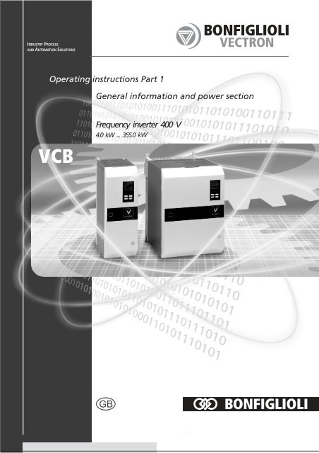
<strong>Operating</strong> instructions <strong>Part</strong> 1<br />
<strong>VCB</strong><br />
General information and power section<br />
Frequency inverter 400 V<br />
4.0 kW ... 355.0 kW<br />
GB
<strong>Operating</strong> instructions <strong>Part</strong> 1<br />
General information and power section<br />
for static frequency inverters VECTRON<br />
<strong>VCB</strong> 400-010 — 4 kW<br />
<strong>VCB</strong> 400-014 — 5.5 kW<br />
<strong>VCB</strong> 400-018 — 7.5 kW<br />
<strong>VCB</strong> 400-025 — 11 kW<br />
<strong>VCB</strong> 400-034 — 15 kW<br />
<strong>VCB</strong> 400-045 — 22 kW<br />
<strong>VCB</strong> 400-060 — 30 kW<br />
<strong>VCB</strong> 400-075 — 37 kW<br />
<strong>VCB</strong> 400-090 — 45 kW<br />
<strong>VCB</strong> 400-115 — 55 kW<br />
<strong>VCB</strong> 400-135 — 65 kW<br />
<strong>VCB</strong> 400-150 — 75 kW<br />
<strong>VCB</strong> 400-180 — 90 kW<br />
<strong>VCB</strong> 400-210 — 110 kW<br />
<strong>VCB</strong> 400-250 — 132 kW<br />
<strong>VCB</strong> 400-300 — 160 kW<br />
<strong>VCB</strong> 400-370 — 200 kW<br />
<strong>VCB</strong> 400-460 — 250 kW<br />
<strong>VCB</strong> 400-570 — 315 kW<br />
<strong>VCB</strong> 400-610 — 355 kW<br />
Item No. of operating instructions 051 001 114<br />
Version: June 2005<br />
P1 06/05 A-1
!<br />
Wait 5 mins after<br />
disconnecting<br />
�<br />
�<br />
�<br />
A IMPORTANT INFORMATION ON THESE OPERATING<br />
INSTRUCTIONS<br />
These operating instructions are valid for the frequency inverter range <strong>VCB</strong> 400.<br />
A list with the relevant control connections and gives information on the handling of<br />
the control unit KP 100, the individual equipment parameters and their parameterisation.<br />
According to the customised request of the frequency inverter, there are also device<br />
versions with special functions. The supplements to the operating instructions<br />
E1, E2 ... describe equipment options and expansion modules. Among other things<br />
the extended control connections with the relevant parameters and setting possibilities<br />
are described.<br />
For more clarity the following pictograms are used in the operating instructions for<br />
warnings and notes.<br />
⇒ Caution! Lethal risk from high direct contact voltage.<br />
⇒ Caution! Instruction must be observed.<br />
⇒ Caution! Disconnect the unit from the mains before performing any operation<br />
and wait few minutes until the DC – link capacitors have discharged to a safe residual<br />
voltage.<br />
⇒ Prohibited! Wrong handling may lead to damaging the equipment.<br />
⇒ Useful note, tip.<br />
⇒ Setting can be changed using the control unit KP 100.<br />
P1 06/05 A-2
Contents<br />
A Important information on these operating instructions............................................A-2<br />
A.1 Further information ..............................................................................................A-4<br />
1 General information ....................................................................................................1-1<br />
1.1 Safety instructions................................................................................................1-1<br />
1.2 Compliance with statutory regulations ................................................................1-1<br />
1.3 Standards and test symbols .................................................................................1-2<br />
1.4 Transport, storage and mechanical handling .......................................................1-2<br />
2 Equipment data...........................................................................................................2-1<br />
2.1 Construction and layout drawing .........................................................................2-1<br />
2.1.1 Construction size 1 (<strong>VCB</strong> 400–010 to –034).............................................................2-1<br />
2.1.2 Construction size 2 (<strong>VCB</strong> 400–045 to –075).............................................................2-2<br />
2.1.3 Construction size 3 (<strong>VCB</strong> 400–090 to –135).............................................................2-3<br />
2.1.4 Construction size 4 (<strong>VCB</strong> 400–150 to –210).............................................................2-4<br />
2.1.5 Construction size 5 (<strong>VCB</strong> 400–250 to –610).............................................................2-5<br />
2.2 Technical data.......................................................................................................2-6<br />
2.2.1 Construction size 1 (<strong>VCB</strong> 400–010 to –034).............................................................2-6<br />
2.2.2 Construction size 2 (<strong>VCB</strong> 400–045 to –075).............................................................2-7<br />
2.2.3 Construction size 3 (<strong>VCB</strong> 400–090 to –135).............................................................2-8<br />
2.2.4 Construction size 4 (<strong>VCB</strong> 400–150 to –250).............................................................2-9<br />
2.2.5 Construction size 5 (<strong>VCB</strong> 400–250 to –370)........................................................... 2-10<br />
2.2.6 Construction size 5 (<strong>VCB</strong> 400–460 to –610)........................................................... 2-11<br />
3 <strong>Instructions</strong> for mechanical installation .....................................................................3-1<br />
3.1 Dimensional drawings of equipment....................................................................3-1<br />
3.1.1 Construction size 1, Standard models (<strong>VCB</strong> 400–010 to –034) .................................. 3-1<br />
3.1.2 Construction size 1, Feed-through model (<strong>VCB</strong> 400–010 to –034) ............................. 3-2<br />
3.1.3 Construction size 2, Standard model (<strong>VCB</strong>400–045 to –075).................................... 3-4<br />
3.1.4 Construction size 2, Feed-through model (<strong>VCB</strong> 400–045 to –075) ............................. 3-4<br />
3.1.5 Construction size 3, Standard models (<strong>VCB</strong> 400–090 to –135) .................................. 3-7<br />
3.1.6 Construction size 3, Feed-through model (<strong>VCB</strong> 400-090 to -135) .............................. 3-8<br />
3.1.7 Construction size 4, Standard models (<strong>VCB</strong> 400–150 and –250).............................. 3-10<br />
3.1.8 Construction size 4, Feed-through model (<strong>VCB</strong> 400-150 to -250) ............................ 3-11<br />
3.1.9 Construction size 5, Standard models (<strong>VCB</strong> 400–250 to –370) ................................ 3-13<br />
3.1.10 Construction size 5, Standard models (<strong>VCB</strong> 400–460 to –610) ................................ 3-14<br />
3.2 Housing protection class ....................................................................................3-15<br />
3.3 <strong>Instructions</strong> for installation of the unit ..............................................................3-15<br />
3.3.1 Reduction diagrams ............................................................................................ 3-15<br />
3.4 Mounting distances.............................................................................................3-16<br />
3.5 Tightening torques of the connection terminals ................................................3-16<br />
P1 06/05 A-3
Contents<br />
4 <strong>Instructions</strong> for electrical installation ........................................................................4-1<br />
4.1 Standards and regulations to be observed...........................................................4-1<br />
4.2 Safety measures ...................................................................................................4-1<br />
4.3 Control equipment................................................................................................4-2<br />
4.4 <strong>Instructions</strong> for EMC safe installation ..................................................................4-2<br />
5 Power connections......................................................................................................5-1<br />
5.1 Mains power connection.......................................................................................5-1<br />
5.1.1 Line choke and DC – link choke..............................................................................5-3<br />
5.1.2 Radio interference suppression filter.......................................................................5-3<br />
5.2 Motor connection..................................................................................................5-3<br />
5.3 Brake unit .............................................................................................................5-6<br />
5.4 Connection of the DC - link circuits ......................................................................5-7<br />
6 General technical data / Licensing by UL and CSA .....................................................6-1<br />
6.1 Marking and specification.....................................................................................6-1<br />
6.2 Notes for the licensing of the drive system..........................................................6-1<br />
6.3 Installation notes .................................................................................................6-2<br />
6.3.1 Super-enclosure ...................................................................................................6-2<br />
6.3.2 Intended use in drive system.................................................................................6-2<br />
6.4 Installation notes .................................................................................................6-3<br />
6.4.1 Mains connection..................................................................................................6-3<br />
6.4.2 Electrical and thermal limit values ..........................................................................6-4<br />
A.1 FURTHER INFORMATION<br />
These operating instructions have been drawn up with the greatest care and have<br />
been extensively checked several times. For reasons of clarity not all detailed information<br />
on all product models and also not every conceivable case of installation,<br />
operation or maintenance could be taken into account. Should you require further<br />
information or if particular problems should occur which are not treated in enough<br />
detail in the operating instructions you may request the necessary information from<br />
the local agent of the company BONFIGLIOLI.<br />
We should like to indicate moreover that the contents of these operating instructions<br />
are not part of a previous or current agreement, confirmation of legal relationship<br />
nor should they amend this. All the manufacturer's obligations ensue from the relevant<br />
sales contract which also includes the complete and solely valid guarantee<br />
regulation. These contractual guarantee conditions are neither extended nor restricted<br />
by implementation of these operating instructions.<br />
The manufacturer retains the right to correct or alter the contents and product details<br />
as well as omissions without previous notice and accepts no liability for damage,<br />
injuries or expenses resulting from the above named reasons.<br />
P1 06/05 A-4
!<br />
!<br />
1 GENERAL INFORMATION<br />
1.1 SAFETY INSTRUCTIONS<br />
While operating inverters can have live parts appropriate to their protection class as<br />
well as hot surfaces. A frequency inverter drive is thus potentially lethal.<br />
To avoid serious injury or severe damage only qualified persons are allowed to work<br />
on the equipment. Persons are qualified who are acquainted with mounting, commissioning<br />
and operation of inverters and have a qualification relevant to their work.<br />
These persons must read the operating instructions carefully before installation and<br />
commissioning and follow the safety instructions.<br />
In this context the norms IEC 364 or CENELEC HD 384 or DIN VDE 0100 and IEC<br />
report 664 or EN 50 178 and VBG 4 and other national regulations must be complied<br />
with.<br />
Repairs in the unit may only be carried out by the manufacturer or repair services<br />
authorised by him. Unauthorised opening and improper intervention can lead to<br />
injury or damage.<br />
1.2 COMPLIANCE WITH STATUTORY REGULATIONS<br />
The frequency inverters of the construction range <strong>VCB</strong> 400 are electrical operating<br />
appliances for the installation in electrical cabinets of industrial plants. They are designed<br />
for the speed adjustment of 3-phase motors.<br />
The frequency inverters are not stand-alone devices. However, they are subject to<br />
the Law with respect to the electromagnetic compatibility of devices (EMVG, from 18<br />
September, 1998, 2 nd re-enactment).<br />
According to this, apparatus, systems and components which are manufactured and<br />
planned exclusively as vendor or spare parts for further processing by companies<br />
and persons with specialist knowledge in the field of electromagnetic compatibility<br />
do not have to meet the protective requirements of the EMC Law. The device which<br />
is ready for work and which contains apparatus, systems or components must comply<br />
with the rules of the law.<br />
The frequency inverters are integrated in a drive system consisting of a number of<br />
components. The electromagnetic compatibility (EMC) only has to be assessed for<br />
the overall system. This is why compliance with the EMC Guideline and EMC Law can<br />
only be achieved through the EMC-compatible design as shown in Chapter 4.4.<br />
A typical drive system which fulfils EMC requirements consists of the following components:<br />
- frequency inverter<br />
- line choke<br />
- radio interference suppression filter<br />
- mains cable - perhaps shielded<br />
- shielded motor cable<br />
- shielded control cables<br />
- standard 3-phase induction motor<br />
- metal mounting plate<br />
P1 06/05 1-1
!<br />
!<br />
These operating instructions (<strong>Part</strong> 1) present measures by which compliance with<br />
the EMC Guideline 89/336/EWG and the EMC Law can be ensured in typical installations.<br />
The responsibility for compliance with the EMC Guideline during the machine's<br />
use rests with the user of the frequency inverter.<br />
We declare that the frequency inverters listed in these operating instructions are<br />
planned as control components for 3-phase motors for installation in a machine or<br />
system in the intendment of the EC Directive 89/392/EWG (Machine Directive).<br />
The machine may not be commissioned until it has been determined that it complies<br />
with the requirements of the EC Directive 89/392/EWG.<br />
The frequency inverters listed in these operating instructions comply with the regulations<br />
of the Commission's Directive from 19 February 1973 on the harmonisation of<br />
the legislative provisions of the member countries as regards electrical resources for<br />
use within certain voltage limits (73/23/EWG Low Voltage Directive).<br />
The technical data and information on the connection and ambient conditions can be<br />
found on the ratings plate and in these operating instructions and must be observed.<br />
1.3 STANDARDS AND TEST SYMBOLS<br />
STANDARDS, TEST SYMBOLS TITEL<br />
EN 50178 (Oct. 1997)<br />
Classification VDE 0160<br />
EN 61800-3 (Oct. 1996)<br />
Classification VDE 0160 <strong>Part</strong> 100<br />
UL test symbol acc. to UL508c<br />
P1 06/05 1-2<br />
Equipping power installations with electronic<br />
resources<br />
Change-speed electric drives<br />
<strong>Part</strong> 3: EMC product standard including<br />
special test method (IEC 1800-3:1996)<br />
UL Standard for Safety for Power conversion<br />
equipment (see chapter 6)<br />
The UL test symbol also indicates that the requirements of the CSA Standard C22.2-<br />
No.14-95 have been met. This is shown on the devices by the combination test symbol.<br />
1.4 TRANSPORT, STORAGE AND MECHANICAL HANDLING<br />
Frequency inverters in the <strong>VCB</strong> 400 series are packed for transportation in boxes or<br />
crates with inlays (acc. to UPS standard) depending on their weight to protect them<br />
against external damage. They should be stored in dry rooms, which are free of dust<br />
and moisture with low temperature fluctuations. They may not be stacked!<br />
Max. permissible ambient conditions at the place of storage acc. to EN 50178:<br />
• Storage temp.: - 25 °C ... +55 °C<br />
• rel.humidity: 15 ... 85%, no condensation<br />
They may not be stored for longer than 1 year. The <strong>VCB</strong> 400 frequency inverter<br />
must be connected to a power supply before the end of one year. It can then be<br />
stored for a further year.<br />
Note: Please check the quality, quantity and type of all incoming goods. Obvious<br />
defects such as external damage to the packaging or the device<br />
must be reported to the sender with seven days for insurance reasons.
�<br />
�<br />
2 EQUIPMENT DATA<br />
2.1 CONSTRUCTION AND LAYOUT DRAWING<br />
Note: The following construction and layout drawings show the standard<br />
model with option assemblies.<br />
2.1.1 CONSTRUCTION SIZE 1 (<strong>VCB</strong> 400–010 TO –034)<br />
P1 06/05 2-1<br />
1<br />
2<br />
3<br />
4<br />
5<br />
6<br />
7<br />
8<br />
1<br />
8<br />
1<br />
15<br />
1<br />
3<br />
8<br />
1<br />
5<br />
1<br />
2<br />
1<br />
8<br />
1<br />
11<br />
1<br />
VECTRON<br />
Item Designation Item Designation<br />
1 Service interface X214 7 Terminal strip X209, relay output<br />
2<br />
Plug connection for the control<br />
unit KP 100 / serial interface X215<br />
8 Terminal X1, power connections<br />
3<br />
Terminal strip X211, analogue<br />
inputs and outputs<br />
9 Fan<br />
4 LED H2 (red) fault message 10 Control unit KP 100<br />
5<br />
6<br />
LED H1 (green) operation message<br />
Terminal strip X210, digital inputs<br />
and outputs<br />
11<br />
to<br />
18<br />
Option, see supplements to the<br />
operating instructions.<br />
9<br />
10<br />
11<br />
12<br />
13<br />
14<br />
15<br />
16<br />
17<br />
18
2.1.2 CONSTRUCTION SIZE 2 (<strong>VCB</strong> 400–045 TO –075)<br />
P1 06/05 2-2<br />
1<br />
2<br />
3<br />
4<br />
5<br />
6<br />
7<br />
8<br />
1<br />
8<br />
1<br />
15<br />
1<br />
3<br />
8<br />
1<br />
5<br />
1<br />
2<br />
1<br />
8<br />
1<br />
11<br />
1<br />
VECTRON<br />
Item Designation Item Designation<br />
1 Service interface X214 7 Terminal strip X209, relay output<br />
2<br />
Plug connection for the control<br />
unit KP 100 / serial interface X215<br />
8 Terminal X1, power connections<br />
3<br />
Terminal strip X211, analogue<br />
inputs and outputs<br />
9 Fan<br />
4 LED H2 (red) fault message 10 Control unit KP 100<br />
5<br />
6<br />
LED H1 (green) operation message<br />
Terminal strip X210, digital inputs<br />
and outputs<br />
11<br />
to<br />
18<br />
Option, see supplements to the<br />
operating instructions.<br />
9<br />
10<br />
11<br />
12<br />
13<br />
14<br />
15<br />
16<br />
17
2.1.3 CONSTRUCTION SIZE 3 (<strong>VCB</strong> 400–090 TO –135)<br />
1<br />
2<br />
3<br />
4<br />
5<br />
6<br />
7<br />
8<br />
P1 06/05 2-3<br />
1<br />
8<br />
1<br />
15<br />
1<br />
3<br />
8<br />
1<br />
5<br />
1<br />
2<br />
1<br />
8<br />
1<br />
11<br />
1<br />
11<br />
12<br />
13<br />
14<br />
15<br />
16<br />
17<br />
18<br />
Rb.2<br />
VECTRON<br />
L1 L2 L3 + -<br />
U V W<br />
Item Designation Item Designation<br />
1 Service interface X214 7 Terminal strip X209, relay output<br />
2<br />
Plug connection for the control<br />
unit KP 100 / serial interface X215<br />
8 Terminal X1, power connections<br />
3<br />
Terminal strip X211, analogue<br />
inputs and outputs<br />
9 Fan<br />
4 LED H2 (red) fault message 10 Control unit KP 100<br />
5<br />
6<br />
LED H1 (green) operation message<br />
Terminal strip X210, digital inputs<br />
and outputs<br />
11<br />
to<br />
18<br />
Option, see supplements to the<br />
operating instructions.<br />
9<br />
10
2.1.4 CONSTRUCTION SIZE 4 (<strong>VCB</strong> 400–150 TO –210)<br />
1<br />
2<br />
3<br />
4<br />
5<br />
6<br />
7<br />
8<br />
P1 06/05 2-4<br />
1<br />
8<br />
1<br />
15<br />
1<br />
3<br />
8<br />
1<br />
5<br />
1<br />
2<br />
1<br />
8<br />
1<br />
11<br />
1<br />
11<br />
12<br />
13<br />
14<br />
15<br />
16<br />
17<br />
18<br />
L1 L2 L3<br />
Item Designation Item Designation<br />
1 Service interface X214 7 Terminal strip X209, relay output<br />
2<br />
Plug connection for the control<br />
unit KP 100 / serial interface X215<br />
8 Terminal X1, power connections<br />
3<br />
Terminal strip X211, analogue<br />
inputs and outputs<br />
9 Fan<br />
4 LED H2 (red) fault message 10 Control unit KP 100<br />
5<br />
6<br />
LED H1 (green) operation message<br />
Terminal strip X210, digital inputs<br />
and outputs<br />
11<br />
to<br />
18<br />
Option, see supplements to the<br />
operating instructions.<br />
VECTRON<br />
10<br />
8<br />
9
2.1.5 CONSTRUCTION SIZE 5 (<strong>VCB</strong> 400–250 TO –610)<br />
P1 06/05 2-5<br />
11<br />
12 13<br />
F1<br />
4<br />
F2<br />
F3<br />
F4<br />
5<br />
8 1<br />
1 8 1<br />
15 1 3<br />
F5<br />
Underneath view<br />
14<br />
1<br />
5<br />
15<br />
2 1<br />
16<br />
8<br />
17<br />
1 11<br />
1 2 3 4 5 6 7<br />
-<br />
8<br />
18<br />
Underneath view<br />
1<br />
+<br />
VECTRON<br />
U V W<br />
L1 L2 L3<br />
Item Designation Item Designation<br />
1 Service interface X214 7 Terminal strip X209, relay output<br />
2<br />
Plug connection for the control<br />
unit KP 100 / serial interface X215<br />
8 Terminal X1, power connections<br />
3<br />
Terminal strip X211, analogue<br />
inputs and outputs<br />
9 Fan<br />
4 LED H2 (red) fault message 10 Control unit KP 100<br />
5<br />
6<br />
LED H1 (green) operation message<br />
Terminal strip X210, digital inputs<br />
and outputs<br />
11<br />
to<br />
18<br />
Option, see supplements to the<br />
operating instructions.<br />
10<br />
10<br />
8<br />
9
2.2 TECHNICAL DATA<br />
2.2.1 CONSTRUCTION SIZE 1 (<strong>VCB</strong> 400–010 TO –034)<br />
<strong>VCB</strong><br />
400-010<br />
P1 06/05 2-6<br />
<strong>VCB</strong><br />
400-014<br />
<strong>VCB</strong><br />
400-018<br />
<strong>VCB</strong><br />
400-025<br />
<strong>VCB</strong><br />
400-034<br />
Output motor side, at 400 V connecting voltage<br />
Recommended<br />
rated motor output<br />
P kW until 4 5.5 7.5 11 15<br />
Equipment continuous<br />
output<br />
S kVA 6.9 9.7 12.5 17.3 23.6<br />
Output current,<br />
effective<br />
I A 10 14 18 25 34<br />
Output voltage,<br />
effective<br />
U V 3 x 0 ... mains voltage input<br />
Overload capacity - 1.2 / 1.5 for 60 s, according to model<br />
Protection short circuit / earth fault<br />
Rotary field frequency f Hz 0 ... 400, according to switching frequency<br />
Switching frequency f kHz 1 ... 8 1 ... 8 1)<br />
Connection terminal A mm 2 Input mains side<br />
0.50 ... 10.00<br />
Recommended<br />
wiring cross section<br />
A mm 2 1.5 2.5 4 6 10<br />
Voltage U V 3 x 400 (-20%) ... 460 (+10%)<br />
Frequency f Hz 50 (-10%) ... 60 (+10%)<br />
Power factor cos φ - ~1 (Power factor of the fundamental)<br />
Efficiency (approx.) η % 98, at 2 kHz switching frequency<br />
Line fuses<br />
Mechanical<br />
Dimensions:<br />
- - external<br />
Standard model WxHxD mm<br />
124x406x262<br />
124x426x264 124x426x274<br />
Feed-through model<br />
124x382x262<br />
124x382x262 124x382x272<br />
Weight (approx.) m kg 6 6.5<br />
Protection class - - IP 20<br />
Installation type - - Vertical wall mounting<br />
Environmental conditions<br />
Dissipation, at<br />
2 kHz switching freq.<br />
P W 164 202 250 320 411<br />
Min. air consumption Q m 3 /h 90 150<br />
Coolant temperature Tn °C 0 ... 40, forced ventilation<br />
Storage temperature TL °C -25 ... +55<br />
Transport<br />
temperature<br />
TT °C -25 ... +70<br />
Relative humidity - % 15 ... 85, no condensation<br />
Power reduction<br />
see Chapter 3.3.1<br />
ΔP %<br />
2.5%/K above 40 °C; Tmax=50 °C;<br />
5%/1000 m above 1000 m above sea level; hmax=4000 m<br />
Options and accessories<br />
Line choke (uk=4%) - -<br />
external,<br />
optional internal DC – link choke<br />
external<br />
EMC filter - - external<br />
Brake chopper - - optional internal external<br />
Digital control unit - - optional<br />
1) From 5kHz switching frequency the output current must be reduced<br />
Internal fuses used<br />
Fuse for switching power supply 1 pc. 2 A/ 600V super-quick-acting, 10 x 38 mm
2.2.2 CONSTRUCTION SIZE 2 (<strong>VCB</strong> 400–045 TO –075)<br />
<strong>VCB</strong><br />
400-045<br />
Output motor side, at 400 V connecting voltage<br />
Recommended<br />
rated motor output<br />
Equipment continuous<br />
output<br />
Output current,<br />
effective<br />
Output voltage,<br />
effective<br />
P1 06/05 2-7<br />
<strong>VCB</strong><br />
400-060<br />
<strong>VCB</strong><br />
400-075<br />
P kW 22 30 37<br />
S kVA 31.2 41.6 52<br />
I A 45 60 75<br />
U V 3 x 0 ... mains voltage input<br />
Overload capacity - 1.2 / 1.5 for 60 s, according to model<br />
Protection short circuit / earth fault<br />
Rotary field frequency f Hz 0 ... 400, according to switching frequency<br />
Switching frequency f kHz 1 ... 8 1 ... 8 1)<br />
Connection terminal A mm 2<br />
Input mains side<br />
16 ... 50<br />
Recommended<br />
wiring cross section<br />
A mm 2<br />
16 25 35<br />
Voltage U V 3 x 400 (-20%) ... 460 (+10%)<br />
Frequency f Hz 50 (-10%) ... 60 (+10%)<br />
Power factor cos φ - ~1 (Power factor of the fundamental)<br />
Efficiency (approx.) η % 98, at 2 kHz switching frequency<br />
Line fuses<br />
Mechanical<br />
- - external<br />
Dimensions:<br />
Standard model<br />
Feed-through model<br />
WxHxD mm<br />
250 x 376 x 317<br />
284 x 428 x 317<br />
Weight (approx.) m kg 17 18 19<br />
Protection class - - IP 20<br />
Installation type - - Vertical wall mounting<br />
Environmental conditions<br />
Dissipation, at<br />
2 kHz switching freq.<br />
P W 527 680 852<br />
Min. air consumption Q m 3 /h 300 350<br />
Coolant temperature Tn °C 0 ... 40 , forced ventilation<br />
Storage temperature TL °C -25 ... +55<br />
Transport<br />
temperature<br />
TT °C -25 ... +70<br />
Relative humidity - % 15 ... 85, no condensation<br />
Power reduction<br />
see Chapter 3.3.1<br />
ΔP %<br />
2.5%/K above 40 °C; Tmax=50 °C;<br />
5%/1000 m above 1000m above sea level; hmax=4000m<br />
Options and accessories<br />
Line choke (u k=4%) - - external<br />
EMC filter - - external<br />
Brake chopper - - optional internal<br />
Digital control unit - - optional<br />
1) From 5kHz switching frequency the output current must be reduced.<br />
Internal fuses used<br />
Fuse for switching power supply 1 pc. 2A / 600V super-quick-acting, 10 x 38 mm
2.2.3 CONSTRUCTION SIZE 3 (<strong>VCB</strong> 400–090 TO –135)<br />
<strong>VCB</strong><br />
400-090<br />
Output motor side, at 400 V connecting voltage<br />
Recommended<br />
rated motor output<br />
Equipment continuous<br />
output<br />
Output current,<br />
effective<br />
Output voltage,<br />
effective<br />
P1 06/05 2-8<br />
<strong>VCB</strong><br />
400-115<br />
<strong>VCB</strong><br />
400-135<br />
P kW 45 55 65<br />
S kVA 62.4 79.7 93.5<br />
I A 90 115 135<br />
U V 3 x 0 ... mains voltage input<br />
Overload capacity - 1.2 / 1.5 for 60 s, according to model<br />
Protection short circuit / earth fault<br />
Rotary field frequency f Hz 0 ... 400, according to switching frequency<br />
Switching frequency f kHz 1 ... 8 1 ... 4<br />
Connection terminal A mm 2<br />
Input mains side<br />
35 ... 95<br />
Recommended<br />
wiring cross section<br />
A mm 2<br />
50 70 95<br />
Voltage U V 3 x 400 (-20%) ... 460 (+10%)<br />
Frequency f Hz 50 (-10%) ... 60 (+10%)<br />
Power factor cos φ - ~1 (Power factor of the fundamental)<br />
Efficiency (approx.) η % 98, at 2 kHz switching frequency<br />
Line fuses<br />
Mechanical<br />
- - external<br />
Dimensions:<br />
Standard model<br />
Feed-through model<br />
WxHxD mm 300 x 602 x 298<br />
300 x 475 x 298<br />
Weight (approx.) m kg 31.5 32.5<br />
Protection class - - IP 20<br />
Installation type - - Vertical wall mounting<br />
Environmental conditions<br />
Dissipation, at<br />
2 kHz switching freq.<br />
P W 1011 1255 1463<br />
Min. air consumption Q m 3 /h 400<br />
Coolant temperature Tn °C 0 ... 40, forced ventilation<br />
Storage temperature TL °C -25 ... +55<br />
Transport<br />
temperature<br />
TT °C -25 ... +70<br />
Relative humidity - % 15 ... 85, no condensation<br />
Power reduction<br />
see Chapter 3.3.1<br />
ΔP %<br />
2.5%/K above 40 °C; Tmax=50 °C;<br />
5%/1000 m above 1000 m above sea level;<br />
hmax=4000m<br />
Options and accessories<br />
Line choke (u k=4%) - - external<br />
EMC filter - - external<br />
Brake chopper - - optional internal<br />
Digital control unit - - optional<br />
Internal fuses used<br />
Fuse for switching power supply 1 pc. 2A / 600V super-quick-acting, 10 x 38 mm<br />
Fuse protection fan 3 pcs. 1.6A / 500V quick-acting, 6.3 x 32 mm
2.2.4 CONSTRUCTION SIZE 4 (<strong>VCB</strong> 400–150 TO –250)<br />
P1 06/05 2-9<br />
<strong>VCB</strong><br />
400-150<br />
<strong>VCB</strong><br />
400-180<br />
<strong>VCB</strong><br />
400-210<br />
<strong>VCB</strong><br />
400-250<br />
Output motor side, at 400 V connecting voltage<br />
Recommended<br />
rated motor output<br />
P kW 75 90 110 132<br />
Equipment continuous<br />
output<br />
S kVA 103.9 124.7 145.5 173,2<br />
Output current,<br />
effective<br />
I A 150 180 210 250<br />
Output voltage,<br />
effective<br />
U V 3 x 0 ... mains voltage input<br />
Overload capacity - 1.2 / 1.5 for 60 s, according to model 1.2 for 60 s<br />
Protection short circuit / earth fault<br />
Rotary field frequency f Hz 0 ... 400, according to switching frequency<br />
Switching frequency f kHz 1 ... 8 1 ... 8 1) 1 ... 4<br />
Connection bolt<br />
Input mains side<br />
- - M8<br />
Recommended<br />
wiring cross section<br />
A mm 2<br />
95 120 150 185<br />
Voltage U V 3 x 400 (-20%) ... 460 (+10%)<br />
Frequency f Hz 50 (-10%) ... 60 (+10%)<br />
Power factor cos φ - ~1 (Power factor of the fundamental)<br />
Efficiency (approx.) η % 98, at 2 kHz switching frequency<br />
Line fuses<br />
Mechanical<br />
Dimensions:<br />
- - external<br />
Standard model WxHxD mm 412 x 510 x 362<br />
Feed-through model<br />
412 x 580 x 362<br />
Weight (approx.) m kg 50<br />
Protection class - - IP 20<br />
Installation type - - Vertical wall mounting<br />
Environmental conditions<br />
Dissipation, at<br />
2 kHz switching freq.<br />
P W 1619 1931 2242 2658<br />
Min. air consumption Q m 3 /h 500<br />
Coolant temperature Tn °C 0 ... 40 , forced ventilation<br />
Storage temperature TL °C -25 ... +55<br />
Transport<br />
temperature<br />
TT °C -25 ... +70<br />
Relative humidity - % 15 ... 85, no condensation<br />
Power reduction<br />
see Chapter 3.3.1<br />
ΔP %<br />
2.5%/K above 40 °C; Tmax=50 °C;<br />
5%/1000 m above 1000 m above sea level;<br />
hmax=4000m<br />
Options and accessories<br />
Line choke (uk=4%) - - external<br />
EMC filter - - external<br />
Brake chopper - - optional internal<br />
Digital control unit - - optional<br />
1) Equipment variant with 6 kHz maximal switching frequency<br />
Internal fuses used<br />
Fuse for switching power supply 1 pc. 2A / 600V super-quick-acting, 10 x 38 mm
2.2.5 CONSTRUCTION SIZE 5 (<strong>VCB</strong> 400–250 TO –370)<br />
<strong>VCB</strong><br />
400-250<br />
Output motor side, at 400 V connecting voltage<br />
Recommended<br />
rated motor output<br />
Equipment continuous<br />
output<br />
Output current,<br />
effective<br />
Output voltage,<br />
effective<br />
P1 06/05 2-10<br />
<strong>VCB</strong><br />
400-300<br />
<strong>VCB</strong><br />
400-370<br />
P kW 132 160 200<br />
S kVA 173.2 207.8 256.3<br />
I A 250 300 370<br />
U V 3 x 0 ... mains voltage input<br />
Overload capacity - 1.5 for 60 s 1.2 / 1.5 for 60 s, according to model<br />
Protection short circuit / earth fault<br />
Rotary field frequency f Hz 0 ... 400, according to switching frequency<br />
Switching frequency f kHz 1 ... 4<br />
Connection bolt<br />
Input mains side<br />
- - M12<br />
Recommended<br />
wiring cross section<br />
A mm 2<br />
185 240 2 x 120<br />
Voltage U V 3 x 400 (-20%) ... 460 (+10%)<br />
Frequency f Hz 50 (-10%) ... 60 (+10%)<br />
Power factor cos φ - ~1 (Power factor of the fundamental)<br />
Efficiency (approx.) η % 98, at 2 kHz switching frequency<br />
Line fuses<br />
Mechanical<br />
- - external<br />
Dimensions WxHxD mm 518x820x406<br />
Weight (approx.) m kg 105 110<br />
Protection class - - IP 20<br />
Installation type - - Vertical wall mounting<br />
Environmental conditions<br />
Dissipation, at<br />
2 kHz switching freq.<br />
P W 2658 3178 3905<br />
Min. air consumption Q m 3 /h 700<br />
Coolant temperature Tn °C 0 ... 40, forced ventilation<br />
Storage temperature TL °C -25 ... +55<br />
Transport<br />
temperature<br />
TT °C -25 ... +70<br />
Relative humidity - % 15 ... 85, no condensation<br />
Power reduction<br />
see Chapter 3.3.1<br />
ΔP %<br />
2.5%/K above 40 °C; Tmax=50 °C;<br />
5%/1000 m above 1000 m above sea level;<br />
hmax=4000m<br />
Options and accessories<br />
Line choke (u k=4%) - - external<br />
EMC filter - - external<br />
Brake chopper - - optional internal<br />
Digital control unit - - optional<br />
Internal fuses used<br />
Fuse for switching power supply 2 pcs. 1A6 / 500V super-quick-acting, 6.3x32 mm<br />
Fuse protection power supply cables 5 pcs. 10A / 500V semi-time-lag, 6.3 x 32 mm
2.2.6 CONSTRUCTION SIZE 5 (<strong>VCB</strong> 400–460 TO –610)<br />
<strong>VCB</strong><br />
400-460<br />
Output motor side, at 400 V connecting voltage<br />
Recommended<br />
rated motor output<br />
Equipment continuous<br />
output<br />
Output current,<br />
effective<br />
Output voltage,<br />
effective<br />
1.2 / 1.5 for 60 s,<br />
Overload capacity -<br />
according to model<br />
P1 06/05 2-11<br />
<strong>VCB</strong><br />
400-570<br />
<strong>VCB</strong><br />
400-610<br />
P kW 250 315 355<br />
S kVA 318.7 395 422.6<br />
I A 460 570 610<br />
U V 3 x 0 ... mains voltage input<br />
1.2 for 60 s<br />
Protection short circuit / earth fault<br />
Rotary field frequency f Hz 0 ... 400, according to switching frequency<br />
Switching frequency f kHz 1 ... 4<br />
Connection bolt<br />
Input mains side<br />
- - M12<br />
Recommended<br />
wiring cross section<br />
A mm 2<br />
2 x 185 2 x 240<br />
Voltage U V 3 x 400 (-20%) ... 460 (+10%)<br />
Frequency f Hz 50 (-10%) ... 60 (+10%)<br />
Power factor cos φ - ~1 (Power factor of the fundamental)<br />
Efficiency (approx.) η % 98, at 2 kHz switching frequency<br />
Line fuses<br />
Mechanical<br />
- - external<br />
Dimensions WxHxD mm<br />
518x820x406 1)<br />
518x1095x406 2)<br />
518x1095x406<br />
Weight (approx.) m kg<br />
110 2)<br />
120 3)<br />
Protection class - - IP 20<br />
Installation type - - Vertical wall mounting<br />
Environmental conditions<br />
Dissipation, at<br />
2 kHz switching freq.<br />
P W 4840 5984 6399<br />
Min. air consumption Q m 3 /h 700 1) , 1200 2) 1200<br />
Coolant temperature Tn °C 0 ... 40, forced ventilation<br />
Storage temperature TL °C -25 ... +55<br />
Transport<br />
temperature<br />
TT °C -25 ... +70<br />
Relative humidity - % 15 ... 85, no condensation<br />
Power reduction<br />
see Chapter 3.3.1<br />
ΔP %<br />
120<br />
2.5%/K above 40 °C; Tmax=50 °C;<br />
5%/1000 m above 1000 m above sea level;<br />
hmax=4000m<br />
Options and accessories<br />
Line choke (u k=4%) - - external<br />
EMC filter - - external<br />
Brake chopper - - optional internal<br />
Digital control unit - - optional<br />
1) 2)<br />
overload capacity 1.2, overload capacity 1.5<br />
Internal fuses used<br />
Fuse for switching power supply 2 pcs. 1A6 / 500V super-quick-acting, 6.3 x 32 mm<br />
Fuse protection power supply cables and fan 5 pcs. 10A / 500V semi-time-lag,<br />
6.3 x 32 mm
!<br />
3 INSTRUCTIONS FOR MECHANICAL INSTALLATION<br />
3.1 DIMENSIONAL DRAWINGS OF EQUIPMENT<br />
3.1.1 CONSTRUCTION SIZE 1,<br />
STANDARD MODELS (<strong>VCB</strong> 400–010 TO –034)<br />
A<br />
B<br />
VECTRON<br />
P1 06/05 3-1<br />
124 C<br />
68<br />
68<br />
Diameter of the fixing holes 7 mm<br />
Dimension table<br />
Unit type A B C D<br />
<strong>VCB</strong> 400-010 to -018 406 mm 390 mm 262 mm 222 mm<br />
<strong>VCB</strong> 400-025 426 mm 410 mm 264 mm 224 mm<br />
<strong>VCB</strong> 400-034 426 mm 410 mm 274 mm 234 mm<br />
Caution:. The air flow direction through the heat sink passes from bottom to top.<br />
The turning direction of the device fan must be noted<br />
D
3.1.2 CONSTRUCTION SIZE 1,<br />
FEED-THROUGH MODEL (<strong>VCB</strong> 400–010 TO –034)<br />
382<br />
366<br />
124<br />
VECTRON<br />
P1 06/05 3-2<br />
84<br />
84<br />
B<br />
Heat sink width<br />
Diameter of the fixing holes 7 mm<br />
Dimension table<br />
342<br />
Unit type A B<br />
<strong>VCB</strong> 400-010 to -018 262 mm 96 mm<br />
<strong>VCB</strong> 400-025 264 mm 96 mm<br />
<strong>VCB</strong> 400-034 274 mm 108 mm<br />
A<br />
199
Drill pattern for feed-through model <strong>VCB</strong> 400-010 to -034<br />
366 344<br />
Diameter of the fixing holes 7mm<br />
Unit type B<br />
<strong>VCB</strong> 400-010 to -025 98 mm<br />
<strong>VCB</strong> 400-034 110 mm<br />
Assembling kit<br />
Number of pieces Designation<br />
2 brackets<br />
4 screws<br />
P1 06/05 3-3<br />
B<br />
84
!<br />
3.1.3 CONSTRUCTION SIZE 2, STANDARD MODEL<br />
(<strong>VCB</strong>400–045 TO –075)<br />
317<br />
250<br />
277<br />
215<br />
70<br />
376 361 343<br />
Diameter of the fixing holes 6.6 mm<br />
Caution: The airflow direction through the heat sink passes from top to bottom.<br />
The turning direction of the device fan must be noted.<br />
3.1.4 CONSTRUCTION SIZE 2, FEED-THROUGH MODEL<br />
(<strong>VCB</strong> 400–045 TO –075)<br />
428<br />
284<br />
250<br />
22 7<br />
264<br />
P1 06/05 3-4<br />
343<br />
7<br />
70<br />
317<br />
277
For assembling in a cabinet there will be required two brackets and one heat conducting<br />
sheet metal for the backside.<br />
The feed-through deep of the heat sink is 70 mm.<br />
Assembling kit<br />
Number of pieces Designation<br />
1 heat conducting sheet metal<br />
2 brackets<br />
1 screw set<br />
Drill pattern for feed-through model <strong>VCB</strong> 400-045 to -075 in construction<br />
size 2<br />
P1 06/05 3-5
!<br />
Attention: The cut in the cabinet has to be 20 mm bigger (see drill pattern) than<br />
the height of the frequency inverter housing; otherwise it is impossible<br />
to pass the device through the cut.<br />
Assembling instruction feed-through model <strong>VCB</strong> 400-045 to -075 in<br />
construction size 2<br />
heat conducting<br />
sheet metal<br />
P1 06/05 3-6<br />
1.<br />
rear panel<br />
3.<br />
2.<br />
4.<br />
bracket<br />
bracket<br />
frequency inverter<br />
1. Screw the heat conducting sheet metal on the backside of the heat sink of the<br />
frequency inverter.<br />
2. Screw one bracket on the underside of the cut of the cabinet rear panel.<br />
3. Pass the frequency inverter with the heat sink through the cut and engage the<br />
slot at the underside to the bracket.<br />
4. Engage the 2 nd bracket at the slot on the upper side and screw the bracket at<br />
the cabinet.
!<br />
3.1.5 CONSTRUCTION SIZE 3,<br />
STANDARD MODELS (<strong>VCB</strong> 400–090 TO –135)<br />
602<br />
556<br />
300<br />
266<br />
Diameter of the fixing holes 10 mm<br />
P1 06/05 3-7<br />
VECTRON<br />
Caution: The airflow direction through the heat sink passes from bottom to top.<br />
The turning direction of the device fan must be noted.<br />
134<br />
258<br />
208<br />
298
3.1.6 CONSTRUCTION SIZE 3,<br />
FEED-THROUGH MODEL (<strong>VCB</strong> 400-090 TO -135)<br />
25<br />
25<br />
400<br />
300<br />
270<br />
VECTRON<br />
Diameter of the fixing holes 7 mm<br />
P1 06/05 3-8<br />
436<br />
73<br />
134<br />
258<br />
208<br />
298<br />
450
Drill pattern for feed-through model <strong>VCB</strong> 400-090 to -135 in construction<br />
size 3<br />
435 402<br />
Diameter of the fixing holes 7 mm<br />
Assembling kit<br />
Number of pieces Designation<br />
2 brackets<br />
4 screws<br />
The feed-through depth of the heat sink is 73 mm. Two brackets and two additional<br />
screws are necessary for the installation into an electrical cabinet.<br />
P1 06/05 3-9<br />
270<br />
Fitting the plate:<br />
1. Undo the fastening screws on the frequency inverter.<br />
2. Fasten the plate onto the top and bottom sides with the three screws.<br />
3. Push the frequency inverter with the heat sink through the opening.<br />
4. Fit the frequency inverter to the rear wall of the control cabinet
!<br />
3.1.7 CONSTRUCTION SIZE 4,<br />
STANDARD MODELS (<strong>VCB</strong> 400–150 AND –250)<br />
480<br />
510<br />
412<br />
392<br />
342<br />
Diameter of the fixing holes 9 mm<br />
VECTRON<br />
Caution: The airflow direction through the heat sink passes from bottom to top.<br />
The turning direction of the device fan must be noted.<br />
P1 06/05 3-10<br />
110<br />
362<br />
322
!<br />
3.1.8 CONSTRUCTION SIZE 4,<br />
FEED-THROUGH MODEL (<strong>VCB</strong> 400-150 TO -250)<br />
480<br />
510<br />
412<br />
392<br />
342<br />
VECTRON<br />
Diameter of the fixing holes 9 mm<br />
Assembling kit<br />
Number of pieces Designation<br />
2 brackets<br />
4 screws<br />
P1 06/05 3-11<br />
110<br />
Caution: The airflow direction through the heat sink passes from bottom to top.<br />
The turning direction of the device fan must be noted.<br />
362<br />
322<br />
580
Drill pattern for feed-through model <strong>VCB</strong> 400-150 to -250<br />
P1 06/05 3-12<br />
504<br />
Diameter of the fixing holes 9 mm<br />
The feed-through depth of the heat sink is 110 mm (see dimensional drawing of the<br />
standard model). Two brackets are necessary for the installation into an electrical<br />
cabinet.<br />
Fitting the plate:<br />
1. Undo the fastening screws on the frequency inverter.<br />
2. Fasten the plate onto the top and bottom sides with the three screws.<br />
3. Push the frequency inverter with the heat sink through the opening.<br />
4. Fit the frequency inverter to the rear wall of the control cabinet<br />
400<br />
342
!<br />
3.1.9 CONSTRUCTION SIZE 5,<br />
STANDARD MODELS (<strong>VCB</strong> 400–250 TO –370)<br />
782<br />
18<br />
P1 06/05 3-13<br />
462<br />
518<br />
Diameter of the fixing holes 9 mm<br />
VECTRON<br />
Caution: The airflow direction through the heat sink passes from bottom to top.<br />
The turning direction of the device fan must be noted.<br />
820<br />
406
!<br />
3.1.10 CONSTRUCTION SIZE 5,<br />
STANDARD MODELS (<strong>VCB</strong> 400–460 TO –610)<br />
782<br />
18<br />
P1 06/05 3-14<br />
462<br />
518<br />
Diameter of the fixing holes 9 mm<br />
VECTR ON<br />
Caution: The airflow direction through the heat sink passes from top to bottom.<br />
Look at the arrow indicated on the side to check the turning direction of<br />
the device fan.<br />
1095<br />
406
�<br />
!<br />
3.2 HOUSING PROTECTION CLASS<br />
The housing protection class is IP 20 according to EN60529. The accident prevention<br />
regulation VBG4 is fulfilled (contact protection).<br />
3.3 INSTRUCTIONS FOR INSTALLATION OF THE UNIT<br />
The frequency inverters are normally supplied for installation in electrical cabinets<br />
with external air flow-through ventilation. The inverters are secured to a mounting<br />
plate with 4 bolts. The inverters must be installed vertically.<br />
Caution: Care must be taken that no foreign bodies like borings or screws fall into<br />
the unit during installation.<br />
Caution, following conditions are required at the installation site:<br />
• max. cooling air inlet temperature: 50 °C<br />
the power must be reduced acc. to the diagrams above 40 °C.<br />
• relative air humidity: 15...85%, no condensation<br />
• max. installation altitude: 4000 m (from 1000 m reduce power)<br />
• the installation site must be free from conductive and aggressive substances as<br />
well as from dampness<br />
3.3.1 REDUCTION DIAGRAMS<br />
120<br />
100<br />
Current, 80<br />
effective 60<br />
in % 40<br />
20<br />
0<br />
105<br />
100<br />
Current, 95<br />
effective 90<br />
in %<br />
85<br />
80<br />
75<br />
35 40 45 50 55<br />
Coolant temperature in °C<br />
500 1000 2000 3000 4000<br />
Mounting altitude in m above sea level<br />
P1 06/05 3-15
3.4 MOUNTING DISTANCES<br />
To avoid a build-up of heat the mounting distances must not be fallen below. The<br />
ventilation openings on the top surface must not on any condition be covered or<br />
closed.<br />
P1 06/05 3-16<br />
B<br />
A<br />
VECTRON VECTRON<br />
A<br />
B B<br />
Inverter type A B<br />
<strong>VCB</strong> 400-010 to -034 100 mm 0 mm<br />
<strong>VCB</strong> 400-045 to -135 100 mm 50 mm<br />
<strong>VCB</strong> 400-150 to -210 300 mm 50 mm<br />
<strong>VCB</strong> 400-250 to -610 300 mm 50 mm 1)<br />
1) The frequency inverters <strong>VCB</strong> 400-570 to -610 are to be separated by a sufficiently<br />
large plate in the area of the device fans. Min. distance to plate 50 mm.<br />
3.5 TIGHTENING TORQUES OF THE CONNECTION<br />
TERMINALS<br />
The frequency inverter range <strong>VCB</strong> 400 differs according to the output in the housing<br />
shape and dimensioning of the connection terminals which depend on the output.<br />
In the following table the torques to be observed when connecting are listed.<br />
Tightening torque<br />
Description Tightening torque<br />
Control terminals of all construction size (Phoenix Combicon) 0.22 – 0.25 Nm<br />
38.5 – 43.7 lb in<br />
Output terminals of construction size 1 (Weidmüller LU10.16) 1.2 Nm<br />
210.1 lb in<br />
Output terminals of construction size 2 (Phoenix HDFK 50) 6 – 8 Nm<br />
1051.7 – 1400 lb in<br />
Output terminals of construction size 3 (Phoenix HDFK 95) 15 – 20 Nm<br />
2626.9 – 3502.5 lb in<br />
PE terminal of construction size 3 (Phoenix HDFK 50) 6 – 8 Nm<br />
1051.7 – 1400 lb in<br />
Output terminals of construction size 4 (insulating bolts) 10 Nm<br />
1751.2 lb in<br />
Output terminals of construction size 5 (set nut in bar) 35 – 40 Nm<br />
6129.4 – 7005 lb in
!<br />
Wait 5 mins after<br />
disconnecting<br />
!<br />
4 INSTRUCTIONS FOR ELECTRICAL INSTALLATION<br />
4.1 STANDARDS AND REGULATIONS TO BE OBSERVED<br />
The general standards and regulations should be observed during electrical installation:<br />
EN 60204 <strong>Part</strong> 1 (Oct. 1992) Classification VDE 0113 <strong>Part</strong> 1<br />
Electrical equipment of machines.<br />
<strong>Part</strong> 1: General requirements.<br />
EN 50178 (Oct. 1997) Classification VDE 0160 <strong>Part</strong> 100<br />
Equipping power installations with electronic resources<br />
Since the leakage current of frequency inverters can be >3.5 mA, a permanent connection<br />
must be provided according to the standard. The PE cross-section must be<br />
at least 10 mm² or a second PE must be laid electrically parallel to the first. In this<br />
case the cross-section has to comply with the recommended cable cross-section of<br />
the cable connection.<br />
Safety instructions:<br />
Do not perform any operations, do not touch any connections and before using<br />
measuring and test equipment wait until the DC - link capacitors have discharged to<br />
less than 50 V residual voltage.<br />
Do not try to check the dielectric strength of the inverter and disconnect its connection<br />
before carrying out any insulation test on the unit. All control inputs and outputs<br />
are isolated from the mains potential!<br />
Caution, danger from high contact voltage:<br />
The device must be safely disconnected from the mains before any intervention.<br />
Wait a few minutes before starting work on the device to allow the DC-link capacitors<br />
to discharge to less than 50 V residual voltage.<br />
Further regulations may have to be observed in the event of special fields<br />
of application.<br />
4.2 SAFETY MEASURES<br />
The following may be used according to the regulations of the local electricity supply<br />
company:<br />
• fault current protection circuit<br />
• fault voltage protection circuit<br />
• protective earth<br />
• neutral<br />
• safety earth conductor system<br />
Note: Fault current protection circuits may be used subject to restrictions in<br />
conjunction with frequency inverters. A universal fault current relay with<br />
leakage current separation has to be used. In some countries this is<br />
forbidden.<br />
There are two reasons for this:<br />
a) All rectifier loads (therefore not only frequency inverters) can cause<br />
a DC current in the mains power supply lines, which can reduce the<br />
sensitivity of the safety switch.<br />
b) Because of an increased leakage current when using a radio interference<br />
suppression filter the fault current safety switch can trip<br />
early which would result in an undesirable failure of the drive system.<br />
P1 06/05 4-1
�<br />
!<br />
4.3 CONTROL EQUIPMENT<br />
According to VDE regulations the inverters must be connected to the mains in such a<br />
way that they can be disconnected from the mains supply by means of appropriate<br />
devices (e g main switch, contactor, circuit breaker). The motor connected to the<br />
inverter may, when loaded, be isolated by a contactor or motor protection switch.<br />
Note: The inverter may be switched to the mains supply only every 60 s. This<br />
means that jogging operation of a mains contactor is not permissible.<br />
For the commissioning phase or after an emergency shutdown it is permitted<br />
to switch the unit on directly once only. Connection of excited<br />
motors or pole-switching in the case of pole-switchable motors as well<br />
as the reversal of the direction of rotation of the motor with a reversing<br />
contactor are not permissible during operation.<br />
4.4 INSTRUCTIONS FOR EMC SAFE INSTALLATION<br />
For the EMC safe mounting and installation of the drive system the instructions listed<br />
below are to be observed.<br />
In case of deviations in the installation e g use of unshielded cables, use of collective<br />
suppressors for several machines instead of an individual suppressor or not using a<br />
power choke the system builder must in each case prove the observance of the limit<br />
values of the drive system separately.<br />
The system builder bears the responsibility for the observance of the limit values for<br />
the EMC of the drive system.<br />
P1 06/05 4-2
Basic rules for the installation of frequency inverters in electrical cabinet<br />
Some basic rules for installation, which can be used for all electrical cabinet installations,<br />
are listed below.<br />
• Ensure a good equipotential bonding within the system or plant. System<br />
components such as switch cabinets, regulation desks, machine frames, etc. are<br />
to be connected by PE – cables of at least 10 mm².<br />
• All metal parts of the electrical cabinet are to be joined to one another on<br />
a plane and highly conductive, not paint on paint. If necessary scraper discs are<br />
to be used. The cabinet door must be connected as closely as possible with the<br />
cabinet case with several ground cables.<br />
• Signal cables and power cables are to be routed with a minimum distance of<br />
20cm.<br />
• The feed and return wires of unshielded cables should be twisted wherever<br />
possible.<br />
• Contactors, relays and magnetic valves in the cabinet must be equipped<br />
with suppressor components: RC combinations, varistors and protective diodes.<br />
• The shields of digital cables are to be connected with the earth on both sides<br />
over a wide area and highly conductive. In the case of poor equipotential bonding<br />
between the shield connections an additional equalizing line of at least<br />
10mm² must be routed parallel to the shield to reduce the shield current.<br />
• The shields of analogue signal cables may only be earthed on one side but<br />
over a wide area and highly conductive. The one-sided shielding prevents cases<br />
of low-frequency, capacitive interference (e g 50 Hz humming). The shield connection<br />
must be effected in the electrical cabinet.<br />
• The braiding-out of shields and the bonding over long single strands (so-called<br />
pig tails) are to be avoided.<br />
• Plug connectors of control cables must be selected so that the connector shell<br />
facilitates a good shield contact.<br />
• Do not route cabling exposed in the cabinet but as close as possible to the<br />
electrical cabinet case (mounting plate) or earth potential.<br />
• Unnecessary lengths of cable must be avoided. Coupling capacities and coupling<br />
inductances are thus kept low.<br />
• If an electrical cabinet consists of the areas power range and control area the<br />
mounting of a metal screen between these areas is recommended. In this case<br />
encircling bonding over a wide area is necessary. This can only be achieved by<br />
removing the painted surface between the frame and the dividing wall and by<br />
screwing down using sheet metal screws. No cables should be routed through<br />
the screen wall. All components for the control of the installation as well as contactors,<br />
which do not lie in the power cables, are to be outside of the area of<br />
power electronics.<br />
Installation of a drive system fulfilling EMC requirements<br />
Components of the drive system given fulfilling EMC requirements:<br />
radio interference see chapter 5.1.2<br />
suppression filter<br />
line choke see chapter 5.1.1<br />
motor cable Shielded cable with tinned E-CU-braid with 85% coverage<br />
Terminal voltage, compliance with limit class B<br />
acc. to the table in Chap. 5.2 (maximum length of cable without<br />
output filter for shielded lines)<br />
power cable between > 300 mm length of cable, shielded power line with tinned E-<br />
radio interference CU-harness with 85% cover<br />
suppression filter and<br />
frequency inverter<br />
signal cable shielded signal lead: type: LIYCY or NYSLYCYÖ-O<br />
P1 06/05 4-3
!<br />
Installation of a drive system fulfilling EMC requirements:<br />
PE<br />
L1<br />
L2<br />
L3<br />
2<br />
Cable shields:<br />
F<br />
Construction size<br />
4 and 5:<br />
P1 06/05 4-4<br />
5<br />
4<br />
1<br />
E<br />
3<br />
9<br />
1<br />
A<br />
B<br />
C<br />
D<br />
7<br />
8<br />
10<br />
M<br />
3 ~<br />
Fasten control and power cable shields in or on device with the enclosed<br />
clips<br />
Also connect motor and power cable shields to the mounting plate<br />
near the device<br />
Position Cable definitions<br />
1<br />
Paint-free metallic mounting<br />
surface<br />
A Control cable<br />
NYSLYCYÖ – O<br />
2 Ground reference point B Reference value cable or<br />
3<br />
4<br />
PE-bar<br />
Choke<br />
C Encoder cable<br />
D PTC resistor monitoring<br />
LIYCY<br />
5 Mains filter E Drive cable e.g. Ölflex–100 CY<br />
6 Control unit F Power cable e.g. Ölflex–100 CY<br />
7 Digital control inputs<br />
8 Analogue inputs<br />
9 Motor PTC resistor monitoring<br />
10 Speed encoder<br />
6
!<br />
Explanations on the EMC safe installation of a drive system:<br />
1. Radio interference suppression filter, line choke, frequency inverter<br />
and PE-bars are to be mounted on the mounting plate over a wide contact<br />
area. Either the mounting points are to be made paint-free or a galvanised<br />
mounting plate is to be used. The above mentioned components are to be<br />
mounted on the same mounting plate.<br />
2. Use only those line chokes and radio interference suppression filters approved<br />
by VECTRON. Both components have been specially selected for these frequency<br />
inverters. They are effective in different frequency ranges.<br />
3. The ground reference point on the mounting plate is the common star point<br />
for the earth potential. All metal conductive drive components are to be connected<br />
through ground lines separately with this ground point. Equipotential<br />
busbars or shield bars can be fitted on the mounting plate, onto which all cable<br />
shields can be connected by use of cable clips. The mounting plate is attached<br />
to the cabinet wall so that it is highly conductive, HF effective (fan discs, HF litz<br />
wire, unpainted connections).<br />
4. The radio interference suppression filter must be installed in the immediate<br />
vicinity of the frequency inverter (max. 50cm). The cable between the radio<br />
interference suppression filter and frequency inverter must be laid with a<br />
shield if longer than 300 mm. Otherwise cross coupling may occur with the unfiltered<br />
input cable of the radio interference suppression filter. The shield must<br />
be connected by clips over a wide area to a PE rail in the vicinity of both the device<br />
and the filter.<br />
5. The power cable between mains and radio interference suppression filter (line<br />
choke) can be any length. However it must be routed separately from control<br />
cables, data cables and motor cable.<br />
6. The shields of all cables between the motor and the frequency inverter must be<br />
connected over a wide area on both sides.<br />
7. The motor cable is a shielded power cable. The shield consists of a tin-plated<br />
E-CU-harness with 85% cover. The motor cable shield should be connected to<br />
the motor with a metal PG joint on the casing of the terminal box. For this the<br />
terminal box must be made of metal and have a perfect metal conductive connection<br />
to the motor casing. If a PVC terminal box is used the cable shield<br />
should be connected to the unpainted motor housing or machine frame with a<br />
cable clip. For better shielding the motor cable can be routed down on the back<br />
of the mounting plate between cabinet rear panel and mounting plate. The motor<br />
cable should be routed without interruption directly from the frequency inverter<br />
to the motor. If the motor cable must be interrupted for contactors or<br />
motor protected switches then the line shield and the PE cable are not to be interrupted.<br />
The cable shield is to be connected with the mounting plate over a<br />
wide area.<br />
8. Line shields are to be connected with earth clips on suitable equipotential<br />
busbars or on the unpainted galvanised mounting plate. Shields from signal and<br />
control cables can, if present, be connected with earth clips in the device.<br />
9. Control lines must be laid separately from power lines. Signal lines should be<br />
kept separate from control lines for contactors or lines for the electronic power<br />
supplies and fan.<br />
10. It must moreover be observed that the motor has a good PE-connection. The<br />
PE-potentials in the electrical cabinet, of the frequency inverter and of the motor<br />
must be identical. Otherwise a potential equalising bar must be routed<br />
between motor and cabinet/device. The cabinet must have a connection with<br />
the equipotential busbar of the building's earth.<br />
P1 06/05 4-5
!<br />
Explanations on the EMC safe installation of a drive system:<br />
11. If filters are fitted then the following points are to be observed: In general the<br />
leakage current increases through the use of filter elements. If this exceeds a<br />
limiting value of 3.5 mA then one of the following conditions must be fulfilled:<br />
• PE cross-section at least 10 mm²<br />
• Monitoring of the protective conductor by an appliance, which leads to an<br />
automatic switching off in the case of a defect.<br />
• Routing of a second cable, electric parallel to the PE via separate terminals.<br />
This must itself fulfil the requirements according to VDE 0100 <strong>Part</strong> 540 (e g<br />
minimum cross-section).<br />
12. In order to achieve as low a load as possible of the supply net in general line<br />
chokes with a short circuit voltage of 4% are used. The line choke is to be<br />
placed between mains connection and radio interference suppression filter.<br />
P1 06/05 4-6
�<br />
�<br />
�<br />
!<br />
5 POWER CONNECTIONS<br />
Note: To deal with the next chapters use the construction and layout drawing<br />
in chapter 2.1.<br />
5.1 MAINS POWER CONNECTION<br />
The mains power connection to the inverter uses the terminals or connection screws<br />
X1-PE, X1-L1, X1-L2 and X1-L3.<br />
Caution: All devices of construction size 3 as well as device types <strong>VCB</strong> 400-570<br />
and <strong>VCB</strong> 400-610 of construction size 5 include a device fan, which is<br />
directly connected internally to the mains connection. This means that<br />
the phase sequence must be observed and checked. Check the direction<br />
of rotation of the device fan using the air current.<br />
The device fans in frequency inverters of construction size 3 draw the air<br />
out of the inverter whereas the air is forced into the inverter in device<br />
types <strong>VCB</strong> 400-570 and <strong>VCB</strong> 400-610.<br />
Note: The following connection diagram also shows the schematic arrangement<br />
of the line choke and the radio interference suppression filter.<br />
To reduce the mains feedback (mains vibrations) a line filter can be used<br />
(see chapter 5.1.1).<br />
To suppress radio interference a radio interference suppression filter can<br />
be used (see 5.1.2).<br />
Terminal strip<br />
Radio interference<br />
Suppression filter<br />
Line choke<br />
Line contactor<br />
Line fuse<br />
P1 06/05 5-1<br />
L1 L2 L3 +<br />
- U V W<br />
PE L1 L2 L3
!<br />
!<br />
Caution: Operation on unearthed mains (IT-mains) is not permissible with the<br />
frequency inverters <strong>VCB</strong> 400 in standard configuration.<br />
(Further information on demand)<br />
P1 06/05 5-2<br />
The mains fuses and the cable cross-sections must be rated according to<br />
the current carrying capacity of the permitted connection cable according<br />
to DIN VDE 0298 <strong>Part</strong> 4. As the leakage current with frequency inverters<br />
can be >3.5 mA a permanent connection must be provided in<br />
accordance with the standard. The PE cross-section in this case must<br />
measure at least 10 mm² or a second PE must be routed electrically<br />
parallel to the first. In this case the cross-section has to comply with the<br />
recommended cable cross-section of the cable connection.<br />
For <strong>VCB</strong> 400-010 to <strong>VCB</strong> 400-180 fuses e g NH fuses of the operating<br />
mode gL (VDE 636, <strong>Part</strong> 1) may be connected in series.<br />
The mains supply must comply with the technical data<br />
(see chapter. 2.2 Technical Data – Input mains side)<br />
Rating example for PVC core cables in electrical installation pipes or channels<br />
at an ambient temperature of 40 °C.<br />
If the routing types, ambient temperatures or insulating raw materials<br />
deviate the cable cross-sections must be selected according to DIN VDE<br />
0298 <strong>Part</strong> 4.<br />
Inverter min. cable cross section line fuses<br />
Type<br />
at 40 °C (mm²)<br />
gL (A)<br />
<strong>VCB</strong> 400-010 1.5 10<br />
<strong>VCB</strong> 400-014 2.5 16<br />
<strong>VCB</strong> 400-018 4 20<br />
<strong>VCB</strong> 400-025 6 25<br />
<strong>VCB</strong> 400-034 10 35<br />
<strong>VCB</strong> 400-045 16 50<br />
<strong>VCB</strong> 400-060 25 63<br />
<strong>VCB</strong> 400-075 35 80<br />
<strong>VCB</strong> 400-090 50 100<br />
<strong>VCB</strong> 400-115 70 125<br />
<strong>VCB</strong> 400-135 95 160<br />
<strong>VCB</strong> 400-150 95 160<br />
<strong>VCB</strong> 400-180 120 200<br />
<strong>VCB</strong> 400-210 150 250<br />
For <strong>VCB</strong> 400-250 to <strong>VCB</strong> 400-610 the semi-conductor fuses given in the<br />
following table must be connected in series.<br />
Frequency Inverter min. cable cross-<br />
line fuses<br />
Type<br />
section at 40 °C (mm²) Ferraz 6.6 URD<br />
<strong>VCB</strong> 400-250 185 30 D . . A0400<br />
<strong>VCB</strong> 400-300 240 31 D . . A0450<br />
<strong>VCB</strong> 400-370 2 x 120 32 D . . A0550<br />
<strong>VCB</strong> 400-460 2 x 185 33 D . . A0700<br />
<strong>VCB</strong> 400-570 2 x 240 33 D . . A0900<br />
<strong>VCB</strong> 400-610 2 x 240 33 D . . A1100<br />
Note: Shielded cables are necessary to suppress radio interference<br />
(see chapter 5.1.2).
Wait 5 mins after<br />
disconnecting<br />
!<br />
5.1.1 LINE CHOKE AND DC – LINK CHOKE<br />
The line and DC – link circuit choke is needed to operate the frequency inverter. It<br />
reduces the commutation glitches and mains feedback.<br />
The inverter types <strong>VCB</strong> 400-010 to -018 can be supplied with an integrated DC –<br />
link choke as an option. For the unit types <strong>VCB</strong> 400-025 and -610 line chokes<br />
with a short circuit voltage of uk = 4% are available as accessories<br />
The diagram in chapter 5.1 mains connection shows the schematic arrangement of<br />
the line choke.<br />
5.1.2 RADIO INTERFERENCE SUPPRESSION FILTER<br />
A radio interference suppression filter, available as an optional extra, must be used<br />
and installed in accordance with Chap. 4.4 to limit the terminal voltage on the power<br />
line.<br />
(Radio interference level acc. to EN 61800-3 for use in living areas)<br />
This complies with the limit class B acc. to EN 55011.<br />
5.2 MOTOR CONNECTION<br />
Caution, lethal risk of electric shock:<br />
Before performing any operation the unit must be disconnected from the mains.<br />
Only after a waiting period of a few minutes, when the DC - link capacitors are discharged<br />
and have a residual voltage of less than 50 V, may work be carried out on<br />
the unit.<br />
The motor connection of the inverter is via the terminals or connecting screws X1-U,<br />
-V, -W and protection switch.<br />
Terminal strip L1 L2 L3 + - U V W<br />
Caution: The cable cross-sections must be rated according to the current carrying<br />
capacity of the permissible connecting cable according to DIN VDE 0298<br />
<strong>Part</strong> 4.<br />
P1 06/05 5-3<br />
M<br />
3~
!<br />
!<br />
Rating example for the cable cross-sections according to DIN VDE 0298<br />
<strong>Part</strong> 4 at an ambient temperature of 40 °C (electrical cabinet inside temperature):<br />
Inverter<br />
Max. continuous Min. cable cross-section<br />
Type<br />
current (A)<br />
at 40 °C (mm²)<br />
<strong>VCB</strong> 400-010 10 1.5<br />
<strong>VCB</strong> 400-014 14 2.5<br />
<strong>VCB</strong> 400-018 18 4<br />
<strong>VCB</strong> 400-025 25 6<br />
<strong>VCB</strong> 400-034 34 10<br />
<strong>VCB</strong> 400-045 45 16<br />
<strong>VCB</strong> 400-060 60 25<br />
<strong>VCB</strong> 400-075 75 35<br />
<strong>VCB</strong> 400-090 90 50<br />
<strong>VCB</strong> 400-115 115 70<br />
<strong>VCB</strong> 400-135 135 95<br />
<strong>VCB</strong> 400-150 150 95<br />
<strong>VCB</strong> 400-180 180 120<br />
<strong>VCB</strong> 400-210 210 150<br />
<strong>VCB</strong> 400-250 250 185<br />
<strong>VCB</strong> 400-300 300 240<br />
<strong>VCB</strong> 400-370 370 2 x 120<br />
<strong>VCB</strong> 400-460 460 2 x 185<br />
<strong>VCB</strong> 400-570 570 2 x 240<br />
<strong>VCB</strong> 400-610 610 2 x 240<br />
Note: Shielded cables are necessary for radio interference suppression. They<br />
should be installed in accordance with Chap. 4.4.<br />
In the case of long motor cables an output filter, available as an accessory,<br />
must be used (see table below). An output filter must also be used<br />
if necessary when using special motors e g high frequency motors or old<br />
motors. A larger output of the frequency inverter may have to be selected<br />
due to the power loss of the filter. Further information is provided<br />
with the corresponding filters.<br />
Caution: The frequency inverter must have an ohmic / inductive load; purely capacitive<br />
loads are not permissible.<br />
Connection of excited motors or switching of the numbers of poles in the<br />
case of pole-switchable motors as well as changing the direction of rotation<br />
of the motor e g by means of a reversing contactor are not permissible<br />
during operation.<br />
In the case of multi-motor drives care must be taken to ensure that the<br />
maximum current for the inverter is not exceeded. The sum total of the<br />
cable lengths for all motors may not exceed the maximum lengths listed<br />
in the table below. The cable lengths can be extended on request by<br />
corresponding technical measures.<br />
P1 06/05 5-4
Maximum cable length without output filter<br />
Frequency Inverter unshielded cables shielded cables<br />
Type<br />
(m)<br />
(m)<br />
<strong>VCB</strong> 400-010 50 35<br />
<strong>VCB</strong> 400-014 70 50<br />
<strong>VCB</strong> 400-018 100 67<br />
<strong>VCB</strong> 400-025 110 75<br />
<strong>VCB</strong> 400-034<br />
<strong>VCB</strong> 400-045<br />
125 85<br />
to<br />
<strong>VCB</strong> 400-610<br />
150 100<br />
Maximum cable length with output filter<br />
Frequency Inverter unshielded cables shielded cables<br />
Type<br />
(m)<br />
(m)<br />
<strong>VCB</strong> 400-010 150 100<br />
<strong>VCB</strong> 400-014 200 100<br />
<strong>VCB</strong> 400-018 225 100<br />
<strong>VCB</strong> 400-025<br />
<strong>VCB</strong> 400-034<br />
240 100<br />
to<br />
<strong>VCB</strong> 400-060<br />
<strong>VCB</strong> 400-075<br />
260 150<br />
to<br />
<strong>VCB</strong> 400-610<br />
300 200<br />
P1 06/05 5-5
Wait 5 mins after<br />
disconnecting<br />
!<br />
�<br />
�<br />
5.3 BRAKE UNIT<br />
Caution, lethal risk of electric shock:<br />
Before any operation the unit is to be disconnected. Only after a waiting period of<br />
approximately a few minutes, when the DC - link capacitors are discharged and have<br />
less than 50 V residual voltage, may any work be carried out on the unit.<br />
If the rotor speed is higher than the corresponding stator speed the motor feeds<br />
energy back to the inverter. In this mode of operation the motor is braked by the<br />
inverter. Depending on the amounts of energy it may become necessary to use an<br />
external brake unit. This converts the volume of energy into heat via a resistor.<br />
The brake unit of the inverter is connected via the terminals or the connecting<br />
screws X1/+ and X1/-.<br />
Terminal strip X1<br />
Power supply<br />
P1 06/05 5-6<br />
L1<br />
L2/N<br />
L1 L2 L3 + - U V W<br />
+ -<br />
~ Brake<br />
Brake chopper<br />
Cable protection<br />
resistor RB<br />
Caution: The cable cross-sections must be rated according to the current carrying<br />
capacity of the permissible connecting cable according to DIN VDE 0298<br />
<strong>Part</strong> 4.<br />
Note: The static frequency inverters in the construction sizes 1 to 5 have to be<br />
ordered with a brake chopper module for the control of an external<br />
brake resistor, which is integrated in the unit. In this configuration two<br />
terminals are available to connect the brake resistor.
Wait 5 mins after<br />
disconnecting<br />
5.4 CONNECTION OF THE DC - LINK CIRCUITS<br />
Caution, lethal risk of electric shock:<br />
Before any operation the unit must be disconnected. Only after a waiting period of<br />
approximately a few minutes, when the DC - link capacitors are discharged and have<br />
less than 50 V residual voltage, may any work be carried out on the unit.<br />
When several drives are working in a motor and generator mode they can be connected<br />
to one another in the DC-link circuit for the exchange of energy. In this case<br />
all inverters must be supplied simultaneously with the same mains voltage and connected<br />
with the recommended line choke or all inverters must be fed by a central DC<br />
- link circuit (DC voltage source). A brake unit is only necessary if for a certain time<br />
the generator energy should be more than the motor energy. The frequency inverters<br />
can optionally be ordered with integrated brake chopper or the VER power unit<br />
can be used.<br />
The connection in the DC - link circuit of the inverters is via the terminals or connecting<br />
screws X1/+ and X1/-.<br />
P1 06/05 5-7<br />
DC - link connection with supply via the mains input<br />
Terminal strip X1 L1 L2 L3 + - U V W<br />
L1 L2 L3 + - U V W<br />
Radio inteference<br />
suppression filter<br />
Line choke<br />
Line fuse<br />
Line contactor<br />
Line fuse<br />
PE L1 L2 L3<br />
Supply voltage<br />
L1<br />
L2/N<br />
Radio inteference<br />
suppression filter<br />
Line choke<br />
Line fuse<br />
Cable protection Cable protection<br />
DC - link circuit connection<br />
+ -<br />
~ Brake<br />
Brake chopper<br />
Cable protection<br />
resistor RB<br />
PE<br />
L1<br />
L2<br />
L3<br />
+<br />
-<br />
To further<br />
frequency<br />
inverters
!<br />
P1 06/05 5-8<br />
DC – link connection with supply via a<br />
a central DC – link circuit<br />
Terminal strip X1 L1 L2 L3 + - U V W<br />
L1 L2 L3 + - U V W<br />
PE<br />
L1<br />
L2<br />
L3<br />
~<br />
Central intermediate<br />
DC circuit<br />
DC - link circuit connection<br />
+<br />
-<br />
To further<br />
frequency<br />
inverters<br />
The central DC - link circuit can be fed via the VER power unit. Further information<br />
can be found in the corresponding documentation.<br />
Note: Linking with a central DC – link circuit is possible with the present frequency<br />
inverters of all output classes.<br />
It must be observed that a 3-phase fan is included in the units of construction<br />
size 3, <strong>VCB</strong> 400-570 and <strong>VCB</strong> 400-670. This must be supplied<br />
with voltage with the correct phase sequence at the optional terminals.<br />
The connecting terminals for the 3-phase fan are not part of the<br />
basic equipment of the frequency inverters and must be given separately<br />
in the order for the named application.
6 GENERAL TECHNICAL DATA / LICENSING BY UL AND CSA<br />
6.1 MARKING AND SPECIFICATION<br />
The devices <strong>VCB</strong> 400-010 to <strong>VCB</strong> 400-135 are tested and licensed by UL as per<br />
UL508c (UL Standard for Safety for power conversion equipment). The requirements<br />
in CSA Standard C22.2 – No.14-95 for frequency inverters are therefore also met.<br />
This is indicated on the device by the combined examination mark.<br />
or<br />
P1 06/05 6-1<br />
83KA Listing mark for standard models<br />
Recognized mark for feed-through<br />
models<br />
6.2 NOTES FOR THE LICENSING OF THE DRIVE SYSTEM<br />
The frequency inverter is part of a more complex drive system that, depending on<br />
the circumstances, must be licensed by UL or CSA. To determine if and which specification<br />
your drive system must meet according to UL or CSA, go to<br />
www.UL.com or www.CSA.ca<br />
to locate the appropriate adviser closest to you.
6.3 INSTALLATION NOTES<br />
6.3.1 SUPER-ENCLOSURE<br />
The frequency inverters <strong>VCB</strong> 400-010 to <strong>VCB</strong> 400-135 are categorized as „open<br />
type“, where the device must be installed in a super-enclosure (control cabinet, machine<br />
frame, etc.). The super-enclosure must not have dimensions of less than<br />
800mm x 500mm x 400mm.<br />
6.3.2 INTENDED USE IN DRIVE SYSTEM<br />
Standard models <strong>VCB</strong> 400-010 bis <strong>VCB</strong> 400-135 83KA<br />
These devices can be directly installed in the drive system. For UL/CSA licensing of<br />
the drive system, the electrical and thermal limit values (see Chapter 6.4.2) and the<br />
installation notes (see Chapter 6.4) must be complied with.<br />
Feed-through models <strong>VCB</strong> 400-010 to <strong>VCB</strong> 400-135<br />
These devices are supplied without device fans and are therefore suitable for integration<br />
within the ventilation concept of the machine so that the device can be<br />
cooled or, alternatively, the actual dissipation power of the frequency inverter can be<br />
separated from the interior of the control cabinet.<br />
For perfect operation of the frequency inverter, forced air cooling of the heat sink is<br />
necessary. The following minimum values must be evidenced for UL/CSA licensing of<br />
the drive system.<br />
<strong>VCB</strong> 400-010 /-014 /-018 > 90 m 3 /h<br />
<strong>VCB</strong> 400-025 /-034 > 150 m 3 /h<br />
<strong>VCB</strong> 400-045 /-060 /-075 > 300 m 3 /h<br />
<strong>VCB</strong> 400-090 /-115 /-135 > 400 m 3 /h<br />
With the appropriate mechanical design, these values can be met using the fans<br />
used for standard devices by Vectron (inquire at factory).<br />
In addition, the electrical and thermal limit values (see Chapter 6.4.2) and the installation<br />
notes (see Chapter 6.4) must be complied with.<br />
P1 06/05 6-2
6.4 INSTALLATION NOTES<br />
6.4.1 MAINS CONNECTION<br />
Connection to a power supply with a short circuit current greater than 18000Arms<br />
and rated voltage greater than 480 Vac is not permitted.<br />
For mains and motor connections, only use UL/CSA approved copper lines with a 75<br />
°C temperature range.<br />
The following tables indicate the permissible fuses and minimum cross-sections for<br />
the mains and motor connections.<br />
Frequency<br />
Inverter type<br />
Over<br />
load<br />
AWG<br />
(min.)<br />
P1 06/05 6-3<br />
Line fuses type Nominal<br />
fuse<br />
current<br />
<strong>VCB</strong> 400-010 1.2 14 class K5 / min. 480 V 10 A<br />
<strong>VCB</strong> 400-010 1.5 14 class K5 / min. 480 V 10 A<br />
<strong>VCB</strong> 400-014 1.2 12 class K5 / min. 480 V 15 A<br />
<strong>VCB</strong> 400-014 1.5 12 class K5 / min. 480 V 15 A<br />
<strong>VCB</strong> 400-018 1.2 10 class K5 / min. 480 V 20 A<br />
<strong>VCB</strong> 400-018 1.5 10 class K5 / min. 480 V 20 A<br />
<strong>VCB</strong> 400-025 1.2 8 class K5 / min. 480 V 25 A<br />
<strong>VCB</strong> 400-025 1.5 8 class K5 / min. 480 V 25 A<br />
<strong>VCB</strong> 400-034 1.2 8 class K5 / min. 480 V 35 A<br />
<strong>VCB</strong> 400-034 1.5 8 class K5 / min. 480 V 35 A<br />
<strong>VCB</strong> 400-045 1.2 6 Semiconductor fuse *)/min. 480 V 80 A<br />
<strong>VCB</strong> 400-045 1.5 6 Semiconductor fuse *)/min. 480 V 100 A<br />
<strong>VCB</strong> 400-060 1.2 4 Semiconductor fuse *)/min. 480 V 100 A<br />
<strong>VCB</strong> 400-060 1.5 4 Semiconductor fuse *)/min. 480 V 125 A<br />
<strong>VCB</strong> 400-075 1.2 3 Semiconductor fuse *)/min. 480 V 125 A<br />
<strong>VCB</strong> 400-075 1.5 3 Semiconductor fuse *)/min. 480 V 160 A<br />
<strong>VCB</strong> 400-090 1.2 2 Semiconductor fuse *)/min. 480 V 160 A<br />
<strong>VCB</strong> 400-090 1.5 2 Semiconductor fuse *)/min. 480 V 200 A<br />
<strong>VCB</strong> 400-115 1.2 1/0 Semiconductor fuse *)/min. 480 V 200 A<br />
<strong>VCB</strong> 400-115 1.5 1/0 Semiconductor fuse *)/min. 480 V 250 A<br />
<strong>VCB</strong> 400-135 1.2 2/0 Semiconductor fuse *)/min. 480 V 250 A<br />
<strong>VCB</strong> 400-135 1.5 2/0 Semiconductor fuse *)/min. 480 V 250 A<br />
* ) Applicable types are, e.g.: Ferraz Type URQ or equivalent (UL/CSA approval is<br />
required)
!<br />
Note: Important note when supplying power through DC terminals:<br />
P1 06/05 6-4<br />
In the frequency inverters <strong>VCB</strong> 400 010 to 025 with integrated retarding<br />
chopper and <strong>VCB</strong> 400 034 to 075, any transient overvoltages of the DC<br />
supply that occur must be limited to 4 kV (e.g. overvoltage protector).<br />
This requirement is met when a Vectron frequency inverter, series<br />
<strong>VCB</strong> 400, is used for the power supply.<br />
6.4.2 ELECTRICAL AND THERMAL LIMIT VALUES<br />
Mains input at ambient temperature of 40 °C<br />
Type<br />
(<strong>VCB</strong> -)<br />
Nominal voltage Frequency Rated current Phases<br />
400-010 400 V (480 V max.) 50 – 60 Hz 10 A<br />
3 ph<br />
540 Vdc (650 V max.) --<br />
12 A<br />
--<br />
400-014 400 V (480 V max.) 50 – 60 Hz 14 A<br />
3 ph<br />
540 Vdc (650 V max.) --<br />
16 A<br />
--<br />
400-018 400 V (480 V max.) 50 – 60 Hz 18 A<br />
3 ph<br />
540 Vdc (650 V max.) --<br />
21 A<br />
--<br />
400-025 400 V (480 V max.) 50 – 60 Hz 25 A<br />
3 ph<br />
540 Vdc (650 V max.) --<br />
29 A<br />
--<br />
400-034 400 V (480 V max.) 50 – 60 Hz 34 A<br />
3 ph<br />
540 Vdc (650 V max.) --<br />
40 A<br />
--<br />
400-045 400 V (480 V max.) 50 – 60 Hz 45 A<br />
3 ph<br />
540 Vdc (650 V max.) --<br />
53 A<br />
--<br />
400-060 400 V (480 V max.) 50 – 60 Hz 60 A<br />
3 ph<br />
540 Vdc (650 V max.) --<br />
71 A<br />
--<br />
400-075 400 V (480 V max.) 50 – 60 Hz 75 A<br />
3 ph<br />
540 Vdc (650 V max.) --<br />
89 A<br />
--<br />
400-090 400 V (480 V max.) 50 – 60 Hz 90 A<br />
3 ph<br />
540 Vdc (650 V max.) --<br />
108 A<br />
--<br />
400-115 400 V (480 V max.) 50 – 60 Hz 115 A<br />
3 ph<br />
540 Vdc (650 V max.) --<br />
138 A<br />
--<br />
400-135 400 V (480 V max.) 50 – 60 Hz 135 A<br />
3 ph<br />
540 Vdc (650 V max.) --<br />
162 A<br />
--<br />
Output at ambient temperature of 40 °C<br />
Type<br />
(<strong>VCB</strong> -)<br />
Nominal voltage Frequency Power Phases<br />
400-010 0 – U input 0 – 400 Hz 6.6 hp (ac) 3 ph<br />
400-014 0 – U input 0 – 400 Hz 9.0 hp (ac) 3 ph<br />
400-018 0 – U input 0 – 400 Hz 12.0 hp (ac) 3 ph<br />
400-025 0 – U input 0 – 400 Hz 17.0 hp (ac) 3 ph<br />
400-034 0 – U input 0 – 400 Hz 23.4 hp (ac) 3 ph<br />
400-045 0 – U input 0 – 400 Hz 33.6 hp (ac) 3 ph<br />
400-060 0 – U input 0 – 400 Hz 45.3 hp (ac) 3 ph<br />
400-075 0 – U input 0 – 400 Hz 55.9 hp (ac) 3 ph<br />
400-090 0 – U input 0 – 400 Hz 67.3 hp (ac) 3 ph<br />
400-115 0 – U input 0 – 400 Hz 82.2 hp (ac) 3 ph<br />
400-135 0 – U input 0 – 400 Hz 97.1 hp (ac) 3 ph
AUSTRALIA<br />
BONFIGLIOLI TRANSMISSION (Aust) Pty Ltd.<br />
48-50 Adderley St. (East) Auburn (Sydney) N.S.W. 2144<br />
Tel. (+61) 2 8748 4400 - Fax (+61) 2 9748 8740<br />
P.o. Box 6705 Silverwater NSW 1811<br />
www.bonfiglioli.com.au - bta1@bonfiglioli.com.au<br />
AUSTRIA<br />
MOLL MOTOR GmbH<br />
Industriestrasse 8 - 2000 Stockerau<br />
Tel. (+43) 2266 63421+DW - Fax (+43) 6342 180<br />
Tlx 61 32 22 348 Molla<br />
www.mollmotor.at - office@mollmotor.at<br />
BELGIUM<br />
N.V. ESCO TRANSMISSION S.A.<br />
Culliganlaan 3 - 1831 Machelem Diegem<br />
Tel. 0032 2 7204880 - Fax 0032 2 7212827<br />
Tlx 21930 Escopo B<br />
www.escotrans.be - info@escotrans.be<br />
BRASIL<br />
ATI BRASIL<br />
Rua Omlio Monteiro Soares, 260 - Vila Fanny - 81030-000<br />
Tel. (+41) 334 2091 - Fax (+41) 332 8669<br />
www.atibrasil.com.br - vendas@atibrasil.com.br<br />
CANADA<br />
BONFIGLIOLI CANADA INC.<br />
2-7941 Jane Street - Concord, ONTARIO L4K 4L6<br />
Tel. (+1) 905 7384466 - Fax (+1) 905 7389833<br />
www.bonfigliolicanada.com - sales@bonfigliolicanada.com<br />
CHINA<br />
BONFIGLIOLI DRIVES (SHANGHAI) CO. LTD.<br />
No. 8 Building, Area C1 - 318<br />
SuHong Road, Qingpu, Shanghai 201700<br />
Tel. +86 21 69225500 - Fax +86 21 69225511<br />
www.bonfiglioli.cn - linkn@bonfiglioli.com<br />
FRANCE<br />
BONFIGLIOLI TRANSMISSIONS S.A.<br />
14 Rue Eugène Pottier BP 19<br />
Zone Industrielle de Moimont II - 95670 Marly la Ville<br />
Tel. (+33) 1 34474510 - Fax (+33) 1 34688800<br />
www.bonfiglioli.fr - btf@bonfiglioli.fr<br />
GERMANY<br />
BONFIGLIOLI DEUTSCHLAND GmbH<br />
Hamburger Straße 18 - 41540 Dormagen<br />
Tel. (+49) 2133 50260 - Fax (+49) 2133 502610<br />
www.bonfiglioli.de - info@bonfiglioli.de<br />
GREAT BRITAIN<br />
BONFIGLIOLI UK Ltd<br />
Unit 3 Colemeadow Road - North Moons Moat<br />
Redditch. Worcestershire B98 9PB<br />
Tel. (+44) 1527 65022 - Fax (+44) 1527 61995<br />
www.bonfiglioli.co.uk - marwaha@bonfiglioli.com<br />
BONFIGLIOLI (UK) LIMITED<br />
5 Grosvenor Grange - Woolston - Warrington, Cheshire WA1 4SF<br />
Tel. (+44) 1925 852667 - Fax (+44) 1925 852668<br />
www.bonfiglioliuk.co.uk - sales@bonfiglioliuk.co.uk<br />
GREECE<br />
BONFIGLIOLI HELLAS S.A.<br />
O.T. 48A T.O. 230 - C.P. 570 22 Industrial Area - Thessaloniki<br />
Tel. (+30) 2310 796456 - Fax (+30) 2310 795903<br />
www.bonfiglioli.gr - info@bonfiglioli.gr<br />
HOLLAND<br />
ELSTO AANDRIJFTECHNIEK<br />
Loosterweg, 7 - 2215 TL Voorhout<br />
Tel. (+31) 252 219 123 - Fax (+31) 252 231 660<br />
www.elsto.nl - imfo@elsto.nl<br />
HUNGARY<br />
AGISYS AGITATORS & TRANSMISSIONS Ltd<br />
2045 Törökbálint, Tö u.2. Hungary<br />
Tel. +36 23 50 11 50 - Fax +36 23 50 11 59<br />
www.agisys.hu - info@agisys.com<br />
INDIA<br />
BONFIGLIOLI TRANSMISSIONS PVT Ltd.<br />
PLOT AC7-AC11 Sidco Industrial Estate<br />
Thirumudivakkam - Chennai 600 044<br />
Tel. +91(0)44 24781035 / 24781036 / 24781037<br />
Fax +91(0)44 24780091 / 24781904<br />
www.bonfiglioli.co.in - bonfig@vsnl.com<br />
NEW ZEALAND<br />
SAECO BEARINGS TRANSMISSION<br />
36 Hastie Avenue, Mangere<br />
Po Box 22256, Otahuhu - Auckland<br />
Tel. +64 9 634 7540 - Fax +64 9 634 7552<br />
mark@saeco.co.nz<br />
POLAND<br />
POLPACK Sp. z o.o. - Ul. Chrobrego 135/137 - 87100 Torun<br />
Tel. 0048.56.6559235 - 6559236 - Fax 0048.56.6559238<br />
www.polpack.com.pl - polpack@polpack.com.pl<br />
RUSSIA<br />
FAM<br />
57, Maly prospekt, V.O. - 199048, St. Petersburg<br />
Tel. +7 812 3319333 - Fax +7 812 3271454<br />
www.fam-drive.ru - info@fam-drive.ru<br />
SPAIN<br />
TECNOTRANS SABRE S.A.<br />
Pol. Ind. Zona Franca sector C, calle F, n°6 08040 Barcelona<br />
Tel. (+34) 93 4478400 - Fax (+34) 93 3360402<br />
www.tecnotrans.com - tecnotrans@tecnotrans.com<br />
SOUTH AFRICA<br />
BONFIGLIOLI POWER TRANSMISSION Pty Ltd.<br />
55 Galaxy Avenue, Linbro Business Park - Sandton<br />
Tel. (+27) 11 608 2030 OR - Fax (+27) 11 608 2631<br />
www.bonfiglioli.co.za - bonfigsales@bonfiglioli.co.za<br />
SWEDEN<br />
BONFIGLIOLI SKANDINAVIEN AB<br />
Kontorsgatan - 234 34 Lomma<br />
Tel. (+46) 40 412545 - Fax (+46) 40 414508<br />
www.bonfiglioli.se - info@bonfiglioli.se<br />
THAILAND<br />
K.P.T MACHINERY (1993) CO.LTD.<br />
259/83 Soi Phiboonves, Sukhumvit 71 Rd. Phrakanong-nur,<br />
Wattana, Bangkok 10110<br />
Tel. 0066.2.3913030/7111998<br />
Fax 0066.2.7112852/3811308/3814905<br />
www.kpt-group.com - sales@kpt-group.com<br />
<strong>USA</strong><br />
BONFIGLIOLI <strong>USA</strong> INC<br />
1000 Worldwide Boulevard - Hebron, KY 41048<br />
Tel.: (+1) 859 334 3333 - Fax: (+1) 859 334 8888<br />
www.bonfiglioliusa.com<br />
industrialsales@bonfiglioliusa.com<br />
mobilesales@bonfiglioliusa.com<br />
VENEZUELA<br />
MAQUINARIA Y ACCESSORIOS IND.-C.A.<br />
Calle 3B - Edif. Comindu - Planta Baja - Local B<br />
La Urbina - Caracas 1070<br />
Tel. 0058.212.2413570 / 2425268 / 2418263<br />
Fax 0058.212.2424552<br />
Tlx 24780 Maica V<br />
www.maica-ve.com - maica@telcel.net.ve<br />
<strong>Bonfiglioli</strong> Worldwide & BEST <strong>Part</strong>ners<br />
HEADQUARTERS<br />
BONFIGLIOLI RIDUTTORI S.p.A.<br />
Via Giovanni XXIII, 7/A<br />
40012 Lippo di Calderara di Reno<br />
Bologna (ITALY)<br />
Tel. (+39) 051 6473111<br />
Fax (+39) 051 6473126<br />
www.bonfiglioli.com<br />
bonfiglioli@bonfiglioli.com<br />
SPARE PARTS BONFIGLIOLI<br />
B.R.T.<br />
Via Castagnini, 2-4<br />
Z.I. Bargellino - 40012<br />
Calderara di Reno - Bologna (ITALY)<br />
Tel. (+39) 051 727844<br />
Fax (+39) 051 727066<br />
www.brtbonfiglioliricambi.it<br />
brt@bonfiglioli.com
INDUSTRY PROCESS<br />
AND AUTOMATION SOLUTIONS<br />
COD. VEC 401 R0<br />
<strong>VCB</strong><br />
www.bonfiglioli.com