250/300/380 sx,mxc,exc repair manual engine - Tanga Moteurs
250/300/380 sx,mxc,exc repair manual engine - Tanga Moteurs
250/300/380 sx,mxc,exc repair manual engine - Tanga Moteurs

You also want an ePaper? Increase the reach of your titles
YUMPU automatically turns print PDFs into web optimized ePapers that Google loves.
Repair <strong>manual</strong> KTM <strong>250</strong> / <strong>300</strong> / <strong>380</strong> Art No 3206004 -E<br />
A<br />
7<br />
5<br />
4<br />
2<br />
9<br />
6<br />
3<br />
8<br />
1<br />
B<br />
6-4C<br />
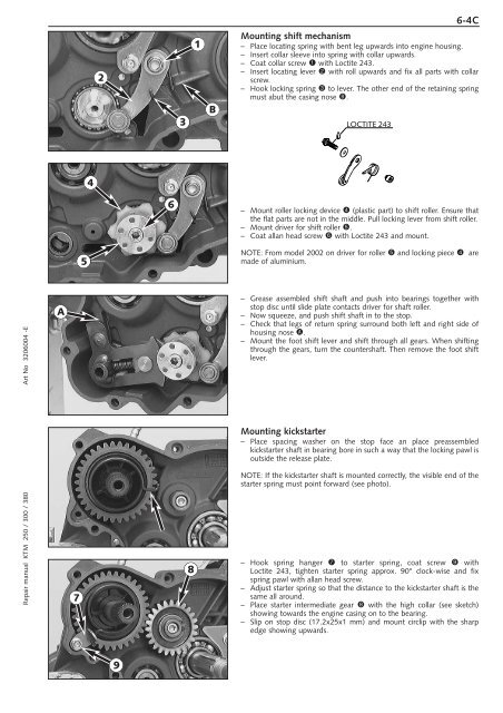
Mounting shift mechanism<br />
– Place locating spring with bent leg upwards into <strong>engine</strong> housing.<br />
– Insert collar sleeve into spring with collar upwards.<br />
– Coat collar screw 1 with Loctite 243.<br />
– Insert locating lever 2 with roll upwards and fix all parts with collar<br />
screw.<br />
– Hook locking spring 3 to lever. The other end of the retaining spring<br />
must abut the casing nose B.<br />
LOCTITE 243<br />
– Mount roller locking device 4 (plastic part) to shift roller. Ensure that<br />
the flat parts are not in the middle. Pull locking lever from shift roller.<br />
– Mount driver for shift roller 5.<br />
– Coat allan head screw 6 with Loctite 243 and mount.<br />
NOTE: From model 2002 on driver for roller 5 and locking piece 4 are<br />
made of aluminium.<br />
– Grease assembled shift shaft and push into bearings together with<br />
stop disc until slide plate contacts driver for shaft roller.<br />
– Now squeeze, and push shift shaft in to the stop.<br />
– Check that legs of return spring surround both left and right side of<br />
housing nose A.<br />
– Mount the foot shift lever and shift through all gears. When shifting<br />
through the gears, turn the countershaft. Then remove the foot shift<br />
lever.<br />
Mounting kickstarter<br />
– Place spacing washer on the stop face an place preassembled<br />
kickstarter shaft in bearing bore in such a way that the locking pawl is<br />
outside the release plate.<br />
NOTE: If the kickstarter shaft is mounted correctly, the visible end of the<br />
starter spring must point forward (see photo).<br />
– Hook spring hanger 7 to starter spring, coat screw 9 with<br />
Loctite 243, tighten starter spring approx. 90° clock-wise and fix<br />
spring pawl with allan head screw.<br />
– Adjust starter spring so that the distance to the kickstarter shaft is the<br />
same all around.<br />
– Place starter intermediate gear 8 with the high collar (see sketch)<br />
showing towards the <strong>engine</strong> casing on to the bearing.<br />
– Slip on stop disc (17.2x25x1 mm) and mount circlip with the sharp<br />
edge showing upwards.