Bedienungsanleitung, Manuel, Manual, Manuale, 9113, PR ...
Bedienungsanleitung, Manuel, Manual, Manuale, 9113, PR ...
Bedienungsanleitung, Manuel, Manual, Manuale, 9113, PR ...

Create successful ePaper yourself
Turn your PDF publications into a flip-book with our unique Google optimized e-Paper software.
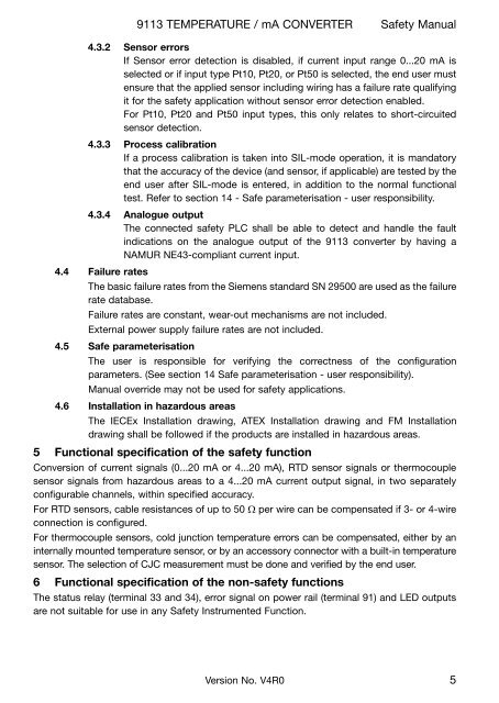
<strong>9113</strong> TeMpeRaTuRe / ma CONVeRTeR Safety <strong>Manual</strong><br />
4.3.2 Sensor errors<br />
If Sensor error detection is disabled, if current input range 0...20 ma is<br />
selected or if input type pt10, pt20, or pt50 is selected, the end user must<br />
ensure that the applied sensor including wiring has a failure rate qualifying<br />
it for the safety application without sensor error detection enabled.<br />
For pt10, pt20 and pt50 input types, this only relates to short-circuited<br />
sensor detection.<br />
4.3.3 process calibration<br />
If a process calibration is taken into SIL-mode operation, it is mandatory<br />
that the accuracy of the device (and sensor, if applicable) are tested by the<br />
end user after SIL-mode is entered, in addition to the normal functional<br />
test. Refer to section 14 - Safe parameterisation - user responsibility.<br />
4.3.4 analogue output<br />
The connected safety pLC shall be able to detect and handle the fault<br />
indications on the analogue output of the <strong>9113</strong> converter by having a<br />
NaMuR Ne43-compliant current input.<br />
4.4 failure rates<br />
The basic failure rates from the Siemens standard SN 29500 are used as the failure<br />
rate database.<br />
Failure rates are constant, wear-out mechanisms are not included.<br />
external power supply failure rates are not included.<br />
4.5 Safe parameterisation<br />
The user is responsible for verifying the correctness of the configuration<br />
parameters. (See section 14 Safe parameterisation - user responsibility).<br />
<strong>Manual</strong> override may not be used for safety applications.<br />
4.6 Installation in hazardous areas<br />
The IeCex Installation drawing, aTeX Installation drawing and FM Installation<br />
drawing shall be followed if the products are installed in hazardous areas.<br />
5 functional specification of the safety function<br />
Conversion of current signals (0...20 ma or 4...20 ma), RTD sensor signals or thermocouple<br />
sensor signals from hazardous areas to a 4...20 ma current output signal, in two separately<br />
configurable channels, within specified accuracy.<br />
For RTD sensors, cable resistances of up to 50 W per wire can be compensated if 3- or 4-wire<br />
connection is configured.<br />
For thermocouple sensors, cold junction temperature errors can be compensated, either by an<br />
internally mounted temperature sensor, or by an accessory connector with a built-in temperature<br />
sensor. The selection of CJC measurement must be done and verified by the end user.<br />
6 functional specification of the non-safety functions<br />
The status relay (terminal 33 and 34), error signal on power rail (terminal 91) and LeD outputs<br />
are not suitable for use in any Safety Instrumented Function.<br />
Version No. V4R0 5
![Bedienungsanleitung Typ BA_8627_8628_8632_DE [PDF, 459 KB]](https://img.yumpu.com/23348412/1/184x260/bedienungsanleitung-typ-ba-8627-8628-8632-de-pdf-459-kb.jpg?quality=85)
![Bedienungsanleitung_Typ BA_optris CT LT_DE [PDF, 4.00 MB]](https://img.yumpu.com/22293726/1/190x133/bedienungsanleitung-typ-ba-optris-ct-lt-de-pdf-400-mb.jpg?quality=85)
![Komplettes Datenblatt Typ 8821_DE [PDF, 499 KB] - MTS ...](https://img.yumpu.com/21876808/1/184x260/komplettes-datenblatt-typ-8821-de-pdf-499-kb-mts-.jpg?quality=85)
![Komplettes Datenblatt Typ 1440_DE [PDF, 524 KB] - MTS ...](https://img.yumpu.com/21876799/1/184x260/komplettes-datenblatt-typ-1440-de-pdf-524-kb-mts-.jpg?quality=85)


![Komplettes Datenblatt Typ 8411_DE [PDF, 459 KB] - MTS ...](https://img.yumpu.com/20642872/1/184x260/komplettes-datenblatt-typ-8411-de-pdf-459-kb-mts-.jpg?quality=85)

![Manual CT13 Serie [PDF, 1.00 MB] - MTS Messtechnik ...](https://img.yumpu.com/20620646/1/184x260/manual-ct13-serie-pdf-100-mb-mts-messtechnik-.jpg?quality=85)
![Komplettes Datenblatt Typ 4503A_DE [PDF, 795 KB] - MTS ...](https://img.yumpu.com/20620634/1/184x260/komplettes-datenblatt-typ-4503a-de-pdf-795-kb-mts-.jpg?quality=85)


![Prüfstandssysteme [PDF, 2.00 MB] - MTS Messtechnik Schaffhausen ...](https://img.yumpu.com/18883102/1/184x260/prufstandssysteme-pdf-200-mb-mts-messtechnik-schaffhausen-.jpg?quality=85)