Bedienungsanleitung, Manuel, Manual, Manuale, 9116, PR - MTS ...
Bedienungsanleitung, Manuel, Manual, Manuale, 9116, PR - MTS ...
Bedienungsanleitung, Manuel, Manual, Manuale, 9116, PR - MTS ...

Create successful ePaper yourself
Turn your PDF publications into a flip-book with our unique Google optimized e-Paper software.
atEX installation Drawings, UK, FR, DE, DK<br />
LERBAKKEN 10, 8410 ROENDE DENMARK<br />
Revision date:<br />
2010-02-12<br />
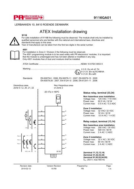
ATEX Installation drawing<br />
Version Revision<br />
V5 R0<br />
Prepared by:<br />
PB<br />
<strong>9116</strong>QA01<br />
<strong>9116</strong><br />
For safe installation of <strong>9116</strong>B the following must be observed. The module shall only be installed by<br />
qualified personnel who are familiar with the national and international laws, directives and<br />
standards that apply to this area.<br />
Year of manufacture can be taken from the first two digits in the serial number.<br />
4501<br />
For installation in Zone 2 / Division 2 the following must be observed.<br />
The 4501 programming module is to be used solely with <strong>PR</strong> electronics’ modules. It is important<br />
that the module is undamaged and has not been altered or modified in any way.<br />
Only 4501 modules free of dust and moisture shall be installed.<br />
ATEX Certificate:.........................................................................KEMA 10 ATEX 0053 X<br />
Marking:....................................................................................... II 3 G Ex nA nC T4<br />
II (1) G [Ex ia] IIC/IIB/IIA<br />
II (1) D [Ex iaD]<br />
Standards EN 60079-0 : 2006, EN 60079-11 : 2007, EN 60079-15 : 2005<br />
EN 60079-26 : 2007, EN 61241-0 : 2006, EN 61241-11 : 2006<br />
Hazardous area Non Hazardous area<br />
Zone 0,1,2, 20, 21, 22 or Zone 2<br />
-20 ≤Ta ≤ +60ºC<br />
Potm. 2<br />
Potm. 3<br />
Potm. 1<br />
+<br />
T<br />
-<br />
4- wire 3- wire 2- wire<br />
RTD / LinR<br />
+<br />
-<br />
Loop V<br />
+<br />
-<br />
mA<br />
-<br />
+<br />
TC<br />
54<br />
53<br />
52<br />
51<br />
44<br />
43<br />
42<br />
41<br />
Power Rail<br />
4501<br />
<strong>9116</strong><br />
34<br />
33<br />
32<br />
31<br />
14<br />
13<br />
12<br />
11<br />
Status relay, terminal (33,34)<br />
Non hazardous area installation<br />
Voltage max: 125 VAC / 110 VDC<br />
Power max: 62.5 VA / 32 W<br />
Current max: 0.5 A AC / 0.3 ADC<br />
Zone 2 installation:<br />
Voltage max: 32 VAC/ 32 VDC<br />
Power max: 16 VA / 32 W<br />
Current max: 0.5 A AC / 1 A DC<br />
Relay output, terminal (13,14)<br />
Non hazardous area installation<br />
Voltage max: 250 VAC / 30 VDC<br />
Power max: 500 VA / 60 W<br />
Current max: 2 A AC / 2 ADC<br />
Zone 2 installation<br />
Voltage max: 32 V AC / 30 VDC<br />
Power max: 64 VA / 60 W<br />
Current max: 2 A AC / 2 ADC<br />
(terminal 11,12,13,14)<br />
(terminal 31,32,33,34)<br />
(terminal 91,92,93,94,95)<br />
Um: 253 V; max 400 Hz<br />
Page:<br />
1/4
![Bedienungsanleitung Typ BA_8627_8628_8632_DE [PDF, 459 KB]](https://img.yumpu.com/23348412/1/184x260/bedienungsanleitung-typ-ba-8627-8628-8632-de-pdf-459-kb.jpg?quality=85)
![Bedienungsanleitung_Typ BA_optris CT LT_DE [PDF, 4.00 MB]](https://img.yumpu.com/22293726/1/190x133/bedienungsanleitung-typ-ba-optris-ct-lt-de-pdf-400-mb.jpg?quality=85)
![Komplettes Datenblatt Typ 8821_DE [PDF, 499 KB] - MTS ...](https://img.yumpu.com/21876808/1/184x260/komplettes-datenblatt-typ-8821-de-pdf-499-kb-mts-.jpg?quality=85)
![Komplettes Datenblatt Typ 1440_DE [PDF, 524 KB] - MTS ...](https://img.yumpu.com/21876799/1/184x260/komplettes-datenblatt-typ-1440-de-pdf-524-kb-mts-.jpg?quality=85)


![Komplettes Datenblatt Typ 8411_DE [PDF, 459 KB] - MTS ...](https://img.yumpu.com/20642872/1/184x260/komplettes-datenblatt-typ-8411-de-pdf-459-kb-mts-.jpg?quality=85)

![Manual CT13 Serie [PDF, 1.00 MB] - MTS Messtechnik ...](https://img.yumpu.com/20620646/1/184x260/manual-ct13-serie-pdf-100-mb-mts-messtechnik-.jpg?quality=85)
![Komplettes Datenblatt Typ 4503A_DE [PDF, 795 KB] - MTS ...](https://img.yumpu.com/20620634/1/184x260/komplettes-datenblatt-typ-4503a-de-pdf-795-kb-mts-.jpg?quality=85)

![Prüfstandssysteme [PDF, 2.00 MB] - MTS Messtechnik Schaffhausen ...](https://img.yumpu.com/18883102/1/184x260/prufstandssysteme-pdf-200-mb-mts-messtechnik-schaffhausen-.jpg?quality=85)